Hi everyone,
Here is my C-Beam / V-Slot build which I have named INDY-TR12, I hope you like it. This is the final design.
Rear drawer, contains the electronics
![[IMG]](https://openbuilds.com/attachments/final2-jpg.40544/?)
![[IMG]](https://openbuilds.com/attachments/final7-jpg.40549/?)
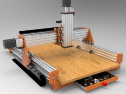
Front drawer for bits / tools etc.
![[IMG]](https://openbuilds.com/attachments/final6-jpg.40548/?)
At first glance the build probably looks like a lot of of others that have been put up on this site, but it's not, it is probably the first build to use TR12x3 lead screws and M8 bolts for the wheel sets. There are a few other differences which I will explain later but two of the main inclusions are a built on back box for the electronics and a built in draw.
Why use M8 bolts?
Rigidity, plain and simple, M8 bolts will not bend anywhere near the amount that M5 bolts will bend under strain. This extra rigidity also means less wheel sets can be used in the build for the same or better grip on the C-Beam. Also, the plates can be smaller in width because the bolts are stronger. The Y plates for instance are only 125mm (5in) wide rather than being around 180mm as a norm. So this gives the build 55mm extra cut length on the long axis. The X/Z plates are also only 125mm wide.
To explain further, this build uses a total of 30 wheel sets, as opposed to the excellent Workbee which uses 54 wheel sets. By utilising M8 bolts rigidity is enhanced and overall costs are reduced.
The wheel sets use an 8mm Inside Diameter flanged bearing.
Why use TR12x3 screws?
I had in mind bigger machines when designing this build, such as 1.5M, and at that length an 8mm screw is simply not a good option, at 1.5M a 12mm screw is better, and less prone to whipping at fast revolving speeds, even at 1.5M length.
Both of these options meant that the build needed different items than are available from OpenBuilds traditional 8mm screws and M5 bolts. I wanted to keep C-Beam in the frame and I wanted the lead nut to fit into the C-Beam inner space.
Well, it took months for me to find the right item, literally months and many, many searches and purchases later I found what I was searching for. I found a lead nut holder that is 39mm width so just fits inside the C-Beam. Now I was on the right track and convinced that I could see this idea working
Then I had to design a screw nut that was able to fit into the holder and was also anti-backlash, which was quite easy but then I had to find a supplier that could make the lead nut at a reasonable price... once again many weeks went by and many searches and purchases took place but eventually due to persistence I found a good supplier.
Here is the holder and Delrin anti-backlash nut, shown with the normal Openbuilds nut side by side. The TR12 nut provides a far greater area of hold.
![[IMG]](https://openbuilds.com/attachments/comparison2-jpg.40328/?)
So, almost set, now I knew at this point that this was a feasible build, so I continue with the design. I still need spacers, shims, and other M8 items that are not off the shelf. These are on order!
I will continue updating as things change
This is the base, the rock on which everything else depends
![[IMG]](https://openbuilds.com/attachments/base2-jpg.40486/?)
The lower wood MDF may be too much but I will have to test this, if this is not used then the draw will rest on the table or other frame.
These are renders of the XYZ, even these show the wheel sets and lead nuts to be solid.
![[IMG]](https://openbuilds.com/attachments/x-z2-jpg.40496/?)
![[IMG]](https://openbuilds.com/attachments/y1-jpg.40498/?)
Now some important changes, and a final design.
A back drawer, that houses the electronics, this uses the dead space at the back of the machine.
A back 'brace' bar, this will be used on any actuator length that is over 800mm, and it will help to stop the C-Beam flex / twist. Basically this reduces the upwards twisting force that is applied to the X/Z axis when machining hard materials. The brace bar has 4 extra wheels attached to the back of the X axis, the top set help reduce vertical stresses and the lower set reduce horizontal stress.
![[IMG]](https://openbuilds.com/attachments/final5-jpg.40547/?)
![[IMG]](https://openbuilds.com/attachments/final3-jpg.40545/?)
![[IMG]](https://openbuilds.com/attachments/final4-jpg.40546/?)
The Y plates of course have changed to accommodate the 40x40 V-Slot profile. If necessary a 20x80 profile can be used, or on smaller length models a 20x40 profile.
Further pictures will be added to the pars list page.
INDY-TR12 CNC (12mm Diameter Lead Screws)
Build in 'Cartesian Style CNC' published by David Bourne, Jun 7, 2019.
TR12x3 screws, M8 wheel sets, a draw built into the design, an electronics set built onto the kit, back brace to stop C-Beam twist.
-
-
Build Author David Bourne, Find all builds by David Bourne
-
- Loading...
-
Build Details
- Build License:
-
- CC - Attribution NonCommercial - No Derivs - CC BY NC ND


