Update Oct 2019: my microsd card died and I went through the setup process again. See details as well as other news in the discussion section of this build.
Hardware & Assembly
I didn't have to cut any of the extrusions for the frame, I just planned the dimensions of my router around what was precut. Prior to putting everything together, I thoroughly washed all the aluminum with soap/water and steel with acetone, drilled the hole (3/4") for the y-axis ballscrew (in the middle of the wider of the two faces) with two tapped holes (#6-32) for mounting the ballscrew support, drilled/tapped two holes in the extrusion for the end bearing opposite the stepper motor on the y axis, drilled/tapped the holes for the x-axis stepper motor (#10 tap to fit what I could make custom spacers for), and tapped the end of the z-axis extrusion (M8-1.25 tap). When designing the 3d printed parts, I made use of the information on 80/20's website: 1530 and Thingiverse: www.thingiverse.com (as well as various datasheets on the rail guides, pillowblocks, ballscrew supports, etc). All parts were printed with ABS plastic.


I started by laying out the base extrusions, the support extrusions for the y axis rails, and the rails themselves. All were attached together with either 5/16"-18 economy t-nuts or #10 nyloc nuts and 3/4" long #10 machine screws with 3d printed nut holders. Both ends of the ballscrew were attached via the supports at this point, making sure to pre-insert any t-nuts that would be needed later on.


I made sure everything was square with the base prior to putting together the gantry extrusions with 5/16"-18 economy t-nuts and attaching the 16mm linear rails via pillowblocks with #10 nyloc nuts and 3/4" long #10 machine screws with 3d printed nut holders. The 8mm leadscrew and pillowblocks were similarly attached along with 3d printed spacers. I used aluminum plates at the corners of the extrusions to reinforce the connection to the base and aluminum blocks to secure the 16mm rail.


I proceeded to attach the gantry to the base with additional aluminum plates and 5/16"-18 economy t-nuts.


The z-axis rails were then attached to the z-axis extrusion with #6 nyloc nuts and 5/8" #6 machine screws with 3d printed nut holders. The pillowblocks for the z-axis leadscrew presented an issue... being metric, they are expected to be attached to metric extrusions and have 44mm center-to-center mounting holes. Since the extrusion t-slots were 1.5" center-to-center (around 38mm), I 3d printed an off-center t-nut holder for a nyloc nut. I also attached a 3d printed brace to the top of the extrusion (M8-1.25 hardware) and secured the stepper motor to it (#10 hardware).


The z-axis was then ready to be attached to the 16mm linear bearings. I again used #10 hardware with 3d printed holders for the Nyloc nuts. Note that the 3d printed piece that attaches the brass leadscrew nut to the z-axis extrusion needed to be beefed up after this photo was taken due to excessive flex.


The x and y stepper motors were then secured with #10 hardware directly to tapped holes with an aluminum plate drilled for securing to the stepper and to the aluminum extrusion (x-axis) or via 3d printed t-nut holders and #10 nyloc nuts holding a bunch of 90 degree mounts (y-axis). Note that this designed did not work very well due to excessive side-to-side motion (along the x-axis direction); the rails were later re-attached to the z-axis extrusion on the front side.

The aluminum plate for the x/y bed did have to be cut to size. I did so on my table saw with a Freud D0756N Diablo 7-1/4 Non-Ferrous Metal and Plastic Cutting Saw Blade. It was my first time cutting aluminum and it worked great. I used wax as a lubricant. I 3d printed a drilling template for attaching the y-axis rail guides (KUE 25 http://www.norfolkbearings.com/products/ina/INA-445-666.pdf) and ballnut but then changed things enough that I needed a new template... which I decided against. I ended up just measuring as carefully as I could, drilling, and countersinking for M12 screws (3/4" countersink). I also drilled/countersunk holes (#12 hardware) for the short piece connecting the ballnut to the x/y bed and drilled holes for securing the MDF spoil board.


I then cut the MDF to size and drilled holes for securing it to the aluminum plate prior to mounting it. After getting everything together enough to use the router to drill a 2" grid pattern in the MDF, I was going to install 1/4"-20 threaded inserts but I was too eager and broke the only appropriately sized drill bit I had the ability to use at that time. I was planning on using the generator at Drilling Rectangle Grid Points. to drill this:

but ended up measuring and drilling by hand.
The router mount was 3d printed and then put together with #10 hardware (attaching mount pieces) and M4 screws (attachment to rail guides), slid into place over the rails, threaded onto the leadscrew, and the router secured in the mount.


At this point, I took a break to put together the electronics enclosure. I secured 4 additional pieces of 1530 aluminum extrusion together with L-brackets and 5/16"-18 hardware. I happened to have a perfectly sized piece of plexiglass handy and secured it with additional 5/16"-18 hardware to the extrusions after drilling holes for the mounting hardware. After laying out where I wanted everything, I secured two DIN rails with #10 hardware, the 36v power supply with M4 bolts, and the 5v power supply with a #6 machine screw after tapping the rear hole. The drivers (already mounted to 3d printed DIN mounts and with 5v fans secured to them) and parallel port BOB (also mounted to 3d printed DIN mounts) were secured to the DIN rails.
The drivers:


The 5 axis BOB:


Everything but the Beaglebone Black and parallel breakout board for the BBB:

The last components that needed to be located in the enclosure were the Beaglebone Black and parallel port breakout board. Since there wasn't room next to the other components, they were mounted to another piece of plexiglass with the idea that the plexiglass could flip outward when access to the components was needed. Unfortunately, for this setup to work, I needed additional depth. I cut some 2x4s to the same size as the aluminum extrusions on 3 sides and attached them with 1/4"-20 hardware. The fourth side was filled with additional 1530 series aluminum extrusion secured to a 4 1/2" door hinge using the included #10 screws and 4 Nyloc nuts in 3d printed nut holders. Before attaching the plexiglass with the Beaglebone Black and breakout board, I drilled holes for attaching a 12v fan.

The electronics enclosure was secured to wall next to the router and everything was wired up. I followed the diagram below initially to match the pinout that some BOB somewhere specified (I forget where):

but over a couple of weeks I settled on:

and hooked up the stepper wires per the datasheet for bipolar/parallel configuration:
http://www.kelinginc.net/KL23H276-30-8B.pdf

I also referenced the following information on the CNC BOB:
101-60-196 - [[:Template:SainSmart Wiki]]

An emergency stop button was mounted to the front of the router:

A router speed control device was zip-tied to the vacuum line that is secured to the wall but eventually I'll either mount the device elsewhere or upgrade to a better spindle with PWM control.
A light layer of synthetic motor oil was rubbed over the rails. This didn't seem to do well so I changed to white lithium grease.
Software & Troubleshooting
An image of Machinekit was loaded up on the Beaglebone Black and I followed instructions for remote access:
Ananthan's Blog : Getting started with BeagleBone Black (Remote login via SSH with Linux / Windows)
Ananthan's Blog : Remote access your BeagleBone Black using vnc
and instructions for installing Cetus:
GitHub - machinekit/Cetus: Full-featured user interface for Machinekit
with the idea of running the Android app:
Machinekit - Android Apps on Google Play
Unfortunately, this setup didn't really work all that well for me. So I purchased cheap HDMI monitor. But my issues were unrelated to Cetus, so I may come back to it at some point.
After configuring everything and making a quick motion test... nothing worked right. The steppers didn't want to move well (seemed like the coils were fighting each other instead of working together). It turns out the TB6600 stepper motor drivers I had were HY-268-N6 boards that are labeled incorrectly as far as A-/A+/B-/B+. If you take off the cover you can see the correct markings on the PCB:

I also had a broken driver (never did figure out the problem) but had an extra to swap out. There are lots of issues with these drivers - the information in this thread was helpful: TB6600 drive from EBAY
I thought I might be having issues with the 3.3v signals out of the BBB into the 5 axis BOB that was probably expecting a 5v parallel port. I looked up the datasheet for the input chip (I forget which one) used on the BOB... it was supposed to be good down to 3.15v if you power it with 4.5v. So I used a dc-to-dc stepdown converter and gave it 4.5v. No change. Then I installed 3.3v to 5v bidirectional signal converters. No change in the behavior. While I left the signal converters in place, I'll bet that my original plan would have worked fine (I used a simple voltage divider for the 5v inputs - the endstops, e-stop, and z-probe before purchasing the signal converters; see How to Level Shift 5V to 3.3V for voltage dividers and the parts list section for the signal converters I used).

The main issue I was having was identified quite quickly at Google Groups - when configuring the BBB, you have to create an .ini and .hal file. I started with a Xylotex cape setup even though I was going capeless. Looking at the .hal file, I mistakenly thought that the line:
loadrt hal_bb_gpio output_pins=812,811,816,815,915,923,930,927,925 input_pins=809,808,810,817,912
Was supposed to set all the pins used as either input or output pins. That is the purpose but only for the gpio driver. The pins used for communicating with the BOB and stepper motor drivers are controlled by the PRU driver and specified later in the .hal file as something like:
setp hpg.stepgen.00.steppin 812
setp hpg.stepgen.00.dirpin 811
That fixed it so all 3 axes moved in both directions but most all of the programs I attempted to run gave me following errors ("joint 1 following error" was the most common). I tried all the solutions Google turned up: 1. Increasing the min_ferror and ferror values (up to 0.5/1). 2. Decreasing the pru_period to 5000. 3. Increasing or decreasing the DEFAULT_VELOCITY and MAX_LINEAR_VELOCITY values. 4. Increasing or decreasing the MAX_VELOCITY and MAX_ACCELERATION for each axis while keeping the stepgen values 20-25% higher than the max velocity/acceleration values. 5. I adjusted the microstepping to lower the steps per inch scale value. Didn't seem to make any difference. I'm currently at 1/2 stepping. 6. I've played with the driver timings (DIRSTEP, DIRHOLD, STEPLEN, STEPSPACE) but they didn't seem to change much. Another post on the Machinekit forum (Google Groups) gave me another thing to try - increase the P value for the PID loop to 1000. Didn't help. I was willing to try using HalScope to try and figure out the issue but I wasn't getting much help on which values I needed to use. Luckily I happened across another post which mentioned G64. The .ini I had copied included the startup gcode G64 P0.1 Q0.1 but when I replaced that with G64 P0.1 (no Q value), the following errors went away and also cleared up another issue I was having:


The white lines are the design, the red lines are where LinuxCNC is commanding the router to actually move. After changing to G64 P0.1, the red lines appear to directly mirror the design.
Accessories & Improvements
To make the router easier to control, I used a cheap USB gamepad and the information at the following sites to configure it:
LinuxCNC (formerly EMC2) > LinuxCNC gamepad (switches only) pendant
LinuxCNC Joystick Pendant Control Example

I was then ready to attach the plexiglass to the sides of the router using 3d printed clips and #6 screws. I drilled and tapped holes in the plexiglass instead of using nuts. The pieces were initially cut as over-sized rectangles with the plan to cut them on the CNC router later.


I wasn't thrilled with any of the dust shoes found on Thingiverse so I designed my own: Parametric CNC Router Dust Shoe by mredmon but found that it decreased by z travel where it ran into the lower pillowblock. I'll have to re-design it.

And hooked up a shop vac with a cheap cyclone separator:

I plan to adapt a dust control idea found on CNC Zone (www.cnczone.com/forums/cnc-wood-router-project-log/135232-cnc-software-forum-posts.html or seen in this video - DustCoverDemo.avi) to keep my y-axis rails covered up.
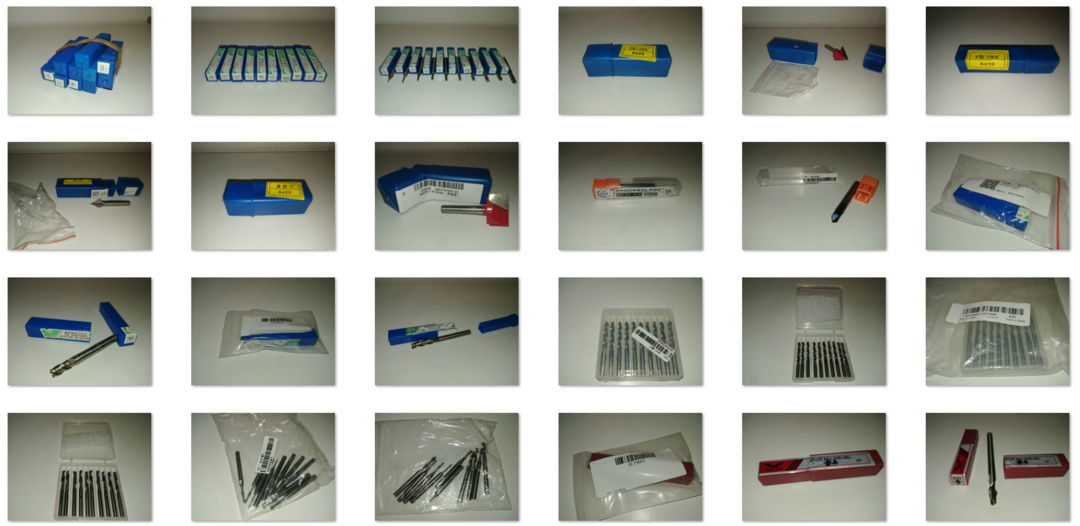
I purchased a selection of cheap endmills off of Ebay, Banggood, and Wish to experiment with:
Initial Projects
It was time to make some gifts for Christmas! I liked the idea of edge-lit LED lights with a custom image or word. I ordered a few bases (2019 RGB Lights LED Lamp Base For 3D Illusion Lamp 4mm Acrylic Light Panel AA Battery Or DC 5V USB 3D Nights Lights From Crestech, $4.44 | DHgate.Com) and created some simple designs to engrave onto an acrylic sheet (I used a 12"x12"x3/16" cast acrylic sheet from https://www.amazon.com/gp/product/B006GHT97Q/ because I was in a time crunch but in the future I'll probably get acrylic from TAP Plastics):


More details on Thingverse: Edge-Lit LED Text Engraving by mredmon
With Christmas out of the way, I moved on to a January birthday. I found this image (American Flag Wall Art, Wooden Flag, Wood Wall Art, Large US Flag Sign, Veterans Day, Military, Anniversary gift, Give me liberty or give me death sign, Patrick Henry, shabby chic, rustic hanging sign) via Pinterest:

I knew right away it was something my brother would love so I Googled for techniques and settled on the following (based on post at How to paint V carve clean):
Lightly sand and clean a piece of 1/2" plywood prior to applying a layer of polyurethane. Allow to dry overnight. Pour a generous coat of rubber cement over the top and spread around with an old giftcard, leaving behind only what couldn't be scraped off with the card. Once dry for 30 minutes, a layer of transfer tape (used for vinyl graphics - not the best stuff to use but it was easily available) was placed over the board and rubbed well with a stiff brush. I then routed it out:

And sprayed with black acrylic paint.

Once dry, the transfer tape and most of the rubber cement pulled right off. Unfortunately, some of it came off/up during routing and I had black paint bleeding onto the non-routed wood. I used some files and sandpaper to remove the extra paint, routed a small round-over into the edges of the board, and applied a coat of polyurethane over everything:

Files at CNC Router American Flag with Liberty Quote by mredmon
Fixed Gantry CNC Router with Old Industrial Supplies
Build in 'X/Y Table Style CNC Mill' published by MattR, Oct 8, 2019.
I got lucky enough to purchase aluminum extrusions and linear motion components (and nuts/bolts/etc) at scrap metal prices when a bunch of industrial automation equipment was decommissioned. The only problem is that the aluminum extrusions are not metric sizes... they are the 1.5"x3" 80/20 series. It has presented a few challenges but nothing too bad.
-
-
Build Author MattR, Find all builds by MattR
-
- Loading...
-
Build Details
- Build License:
-
- CC - Attribution - CC BY
Reason for this Build
I built it for fun and to make custom gifts for family and friends.Inspired by
I've been inspired by many of the builds I've looked at over the years, most recently the C-Beam Machine XLarge. -
Parts list
Qty Part Name Part Link Comments 1 1530 Series Aluminum Extrusion https://8020.net/shop/1530.html Link Try and get surplus extrusions if you can... much cheaper ")
10 Corner braces, 90 degree Link 4 Joining plates, 90 degree Link 1 T-nuts Link MANY needed 2 INA Series KUE25 Linear Rails http://medias.ina.de/medias/en!hp.ec.br.dat/KUE*KUE25 Link 4 INA Series KUE25 Linear Guides http://medias.ina.de/medias/en!hp.ec.br.dat/KUE*KUE25 Link 2 16mm Linear Rail Link 4 16mm Linear Bearings Link 4 16mm Pillowblocks Link 2 THK SR15 Linear Rails https://tech.thk.com/en/products/thkdlinks.php?id=315# Link 4 THK SR15-W Linear Guides https://tech.thk.com/en/products/thkdlinks.php?id=315# Link 1 SFU1605 Ballscrew kit https://www.wish.com/c/set-of-antibacklash-ball-screw-sfu... Link 0 8mm Lead Screw Kit https://www.amazon.com/gp/product/B01H1QGGEE/ Link 0 8mm Leadscrew with separate antibacklash nut, etc http://openbuildspartstore.com/8mm-metric-acme-lead-screw/ Link 3 NEMA23 282oz/in 3A Stepper Motors - ¼” 2 shaft https://www.automationtechnologiesinc.com/products-page/s... Link You don't need the 2 shaft versions but it is kind of nice being able to manually position the axes if needed. 1 36v power supply https://www.amazon.com/gp/product/B01HTH0MUE/ Link This also powers the 12v pieces of the BOB via a stepdown DC converter. 1 5v power supply https://www.amazon.com/gp/product/B019P1F4E6/ Link 1 Beaglebone Black https://www.amazon.com/gp/product/B00LC1924G/ Link 4 5V 80mm fans https://www.amazon.com/gp/product/B06ZXXT6L9/ Link 2 8mm to 1/4" flexible couplings https://www.amazon.com/gp/product/B06XGBV616/ Link 2 8mm pillowblocks https://www.amazon.com/gp/product/B01KJUODVW/ Link 1 8mm antibacklash nut https://www.amazon.com/gp/product/B01MR2JNT5/ Link 16 M8-1.25 x 20 screws for the KUE25 guides Link 1 Parallel port breakout board https://www.sainsmart.com/products/cnc-5-axis-breakout-bo... Link I have an older version of this product. 1 Harbor Freight Trim Router https://www.harborfreight.com/14-in-24-amp-trim-router-62... Link 1 Harbor Freight Router Speed Control https://www.harborfreight.com/router-speed-control-43060.... Link 1 Aluminum plate for xy bed Link 1 MDF for xy bed Link 1 Parallel Port Breakout Board http://xylotex.netfirms.com/OSCommerce/catalog/product_in... Link Makes it easier to re-configure pins as needed. 2 3.3v to 5v signal converter https://www.amazon.com/gp/product/B075PSB71D/ Link May not be necessary but doesn't hurt. 1 Cheap HDMI monitor https://www.amazon.com/gp/product/B07743412C/ Link Probably wouldn't have purchased if I hadn't had configuration issues. 60 1/4-20 threaded inserts https://www.amazon.com/gp/product/B07H2BYRML/ Link 1 Z-probe Touch Plate https://www.aliexpress.com/item/CNC-Z-Axis-Router-Mill-Ze... Link 1 USB gamepad Link I don't remember where I got this one... any cheap gamepad would probably work but it helps to find one that already has the configuration stuff figured out. -
Attached Files:


