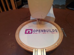
I was thinking about a winter project when the Missus informed me that she fancied an embroidery machine. Although there seemed plenty of options, I got to thinking that perhaps I could adapt her relatively cheap sewing machine. This site helped me to quickly understand the many options that would be available to me.
The main requirement is to control a 2D XY arm that positions the embroidery hoop as required. In addition, the machine also requires control of the sewing machine mains supply, and some means of reliably detecting the needle position.
I came across the V-Slot belt and pinion drive, as published on this site, and set about creating a 2D version using a single gantry plate with drives on opposing sides.The attached sketch-up file shows the final concept, and it is this design that became the prototype.


The type 17 stepper motors use a pinion with 20 teeth driving a 2mm pitch belt (rack). Thus one full revolution gives a displacement of 40mm - this results in a resolution of 0.1mm when used in half step mode. The stepper drives were purchased from EBAY and use the very common L298 driver. I used a 12V supply and pulse width modulation to control the maximum drive current.
The heart of the system is based around a 16F73 PIC Microcontroller that provides the stepper motor control and current regulation. The speed is set at a relatively sluggish 500 steps/s for both axes, avoiding the need for relatively complex acceleration/deceleration profiles. The PIC chip also monitors the mains zero crossing and controls the trigger delay for the TRIAC - used to control power to the sewing machine motor. Both these circuits are opto-isolated to ensure separation from the main supply - this should not be attempted unless you are experienced in the field!
The needle position detection proved quite tricky, but a simple solution using some very fine spring steel gave me the detection required.
Finally, communications to the PIC chip was via serial I/O - using a simple ascii command set running at 38400 Baud.
The high level interaction is provided by an Android tablet (Nexus 7) with code on this developed using Eclipse. Bluetooth connection was provided by adding a widely available Ebay Bluetooth module to the embedded board. I probably spent just as much time with Eclipse as I did on the rest of the project put together. My background is C++ using MS Visual Studio 2010 and it took quite a bit of conversion to get into the Java world!
Apologies for the poor quality of the short video:
Although the colours are a bit naff - the final result looks ok:

I should have trimmed the interconnecting threads - but I didn't have a pair of small scissors to hand! This is not bad as part of the initial trails - especially considering that I didn't use any stabiliser on the rear of material.
Embroidery machine with XY belt and pinion drive.
Build in 'Everything Else' published by sausagePaws, Apr 22, 2014.
A simple Embroidery machine using an XY belt and pinion drive to drive a hoop under a standard sewing machine. Needle timing, machine power and stepper control are all provided by a PIC processor. A tablet provides the higher level formatting required for communicating with the PIC chip.
-
-
-
- Build Progress:
-
- Build in Progress...
Rodrigo Ibañez Mamani, savasss, STovey and 80 others like this. -
-
Build Author sausagePaws, Find all builds by sausagePaws
-
- Loading...
-
Build Details
- Build License:
-
- CC - Attribution - CC BY
Reason for this Build
To show the missus that something useful can occasionally result from my many hours in the garage and in front of my PC! -
Attached Files:
-

