This all started for me last year in October. For the previous 2 or 3 years I had dreamed of making a CNC machine to make PCB's and small aluminum parts. I finally had the means and space to begin my build. After non-stop talking about what I wanted to build, my wife gave me a birthday gift of a $500 budget to build whatever I wanted. So it began...
Version 1
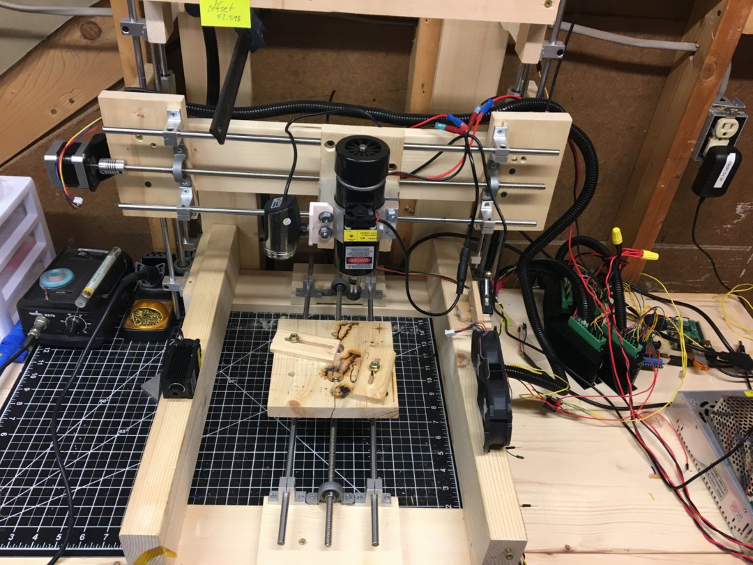
I didn't document this build other than all my hand notes in my "lab" book. I learned a ton about alignment and rigidity of the machine. Version 1 consisted of 4x NEMA 17 stepper motors (double z), TB6600 drivers, with 8mm lead screws and linear rod slides. A cheap 500W spindle and a .5W 445nm laser as well as a 2.5W 445nm laser. All held together with dimensional lumber. Everything was driven by an Arduino UNO with GRBL1.1 and BCNC running on a headless raspberry pi. I utilize VNC viewer to establish a remote connection for control.
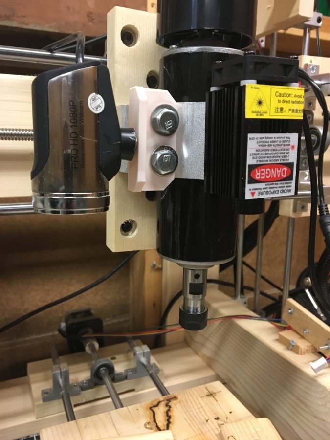
The 0.5W laser took a very long time to dial in. Achieving a good engraving was very difficult as the focal point for engraving was only good within +/- 0.2mm. The 2.5W laser proved much better at marking and could go at speeds 4 times faster than the weaker laser. I frequently encountered screws loosing in the wood resulting in skewed markings. The spindle worked great in soft wood and acrylic. I drilled and tapped a 1/4-20 hole in the spindle mount and using a 0.5" set screw I am able to mount either laser on the spindle mount.
Version 2
Introduction:
Fast forward a year. I know i needed to strengthen the machine and aluminum extrusion seemed like the best option. I also wanted to upgrade to all ball screws and NEMA 23 steppers. I stated working in SolidWorks planning out how i wanted to accomplish this without hurting my bank account too much. After multiple weekends of planning and contemplating I ended up deciding on utilizing all of my original motion control components and with the exception of the linear guides. I opted for the v-slot and wheel configuration.I also know that I needed to re-work all of the controls. I design electrical and mechanical assemblies for a living and what I had was just completely unacceptable from both a safety and visual appearance perspective. I had at least 2 small fires from the 12Vdc power supply inadvertently shorting.
Motion:
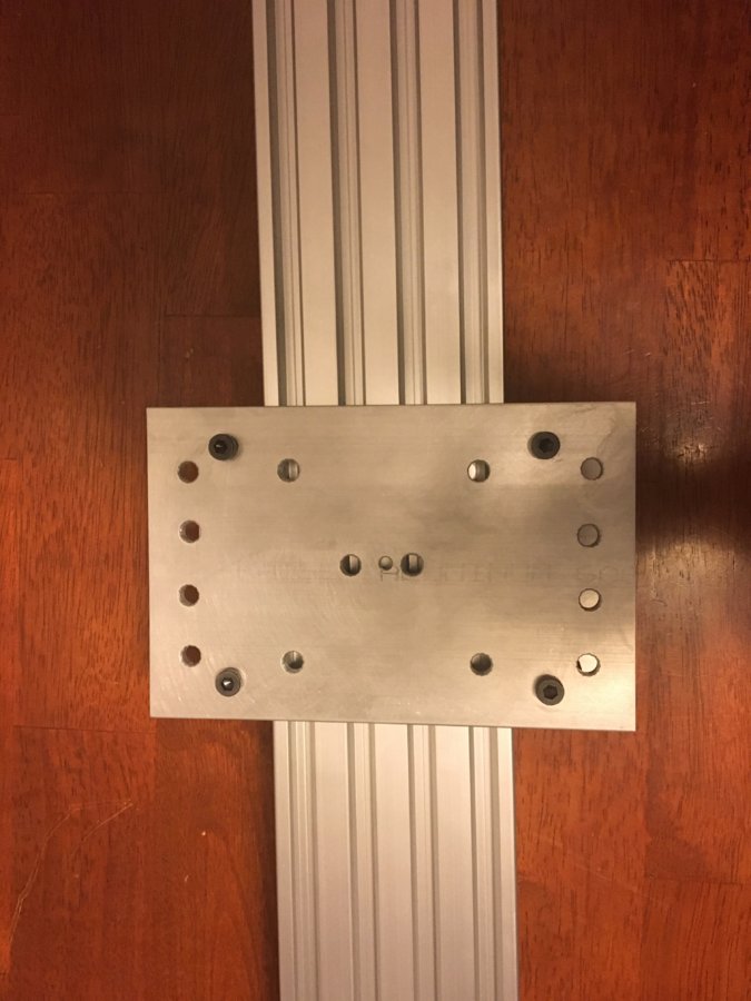
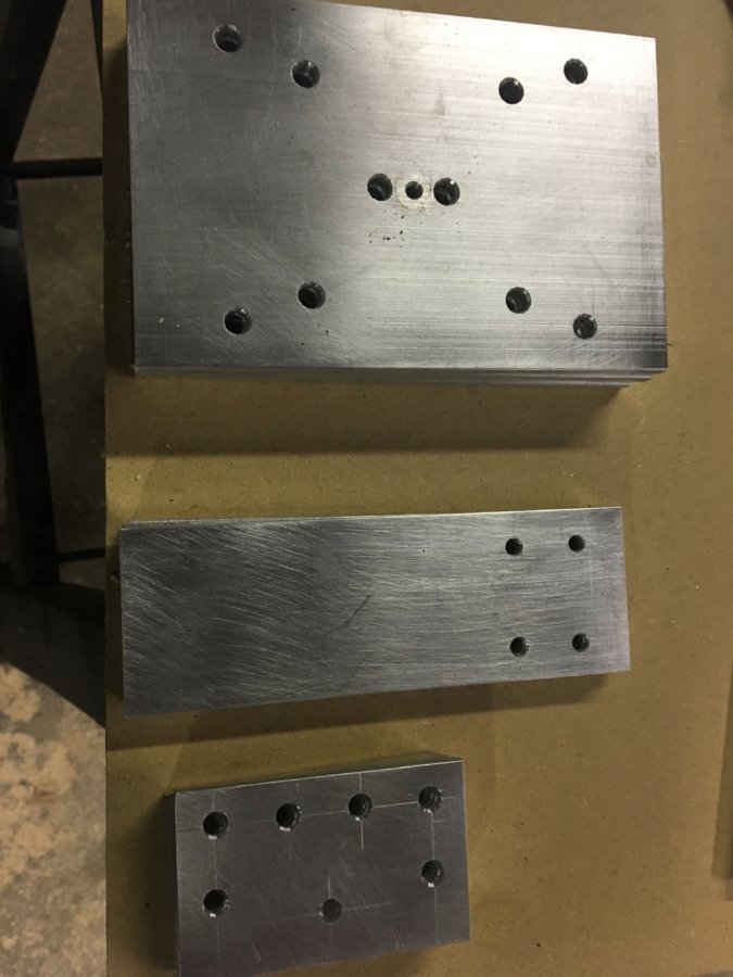
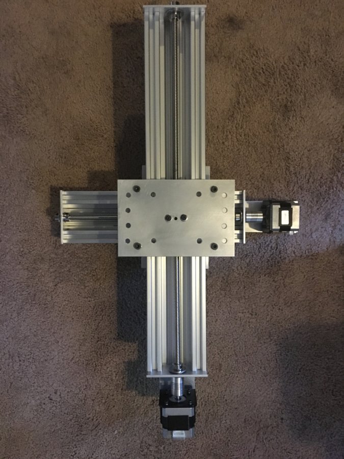
After planning out a few strategies I went with C-Beam extrusions and v-slot wheels. These are the key components of each axis. One big mistake I made was not planning out assembly procedures and fastener accessibility. I worked out a fairly good assembly however it took way to many full assembles and disassembles before I got it to a point that I was happy. I had a bunch of scrap aluminum and wanted to utilize this instead of purchasing pre-machined plates. My goal was to have all plates have the same layout so I could print and laminate a template and mimic an assembly line for a few nights. This is the template I used for the axis plates.
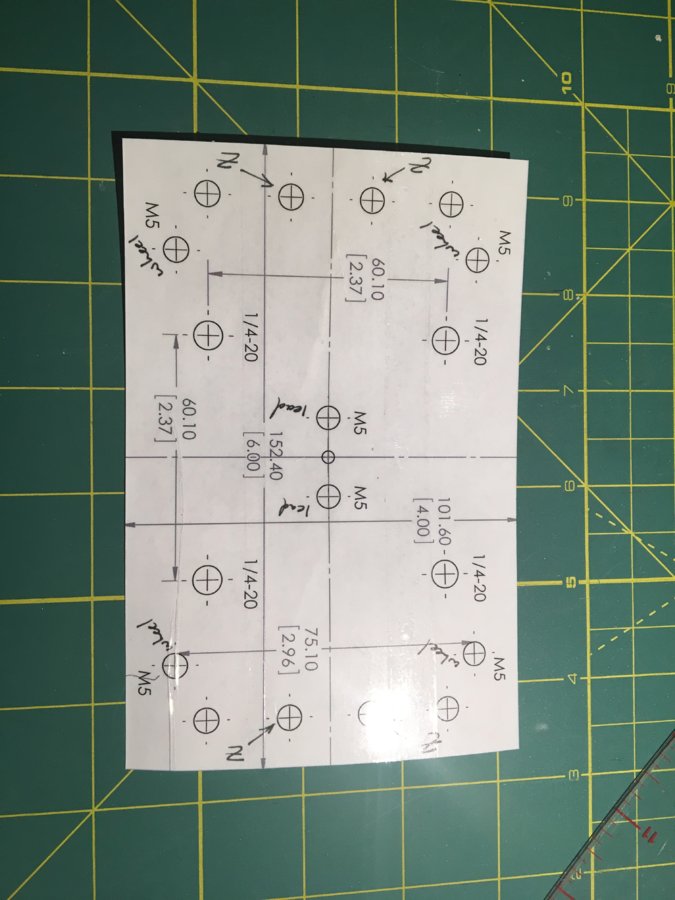
Not all holes were drilled for every axis but were marked on the template. This worked very well and gave very consistent results.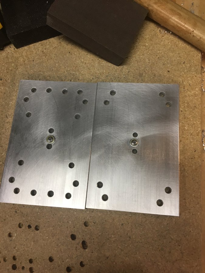
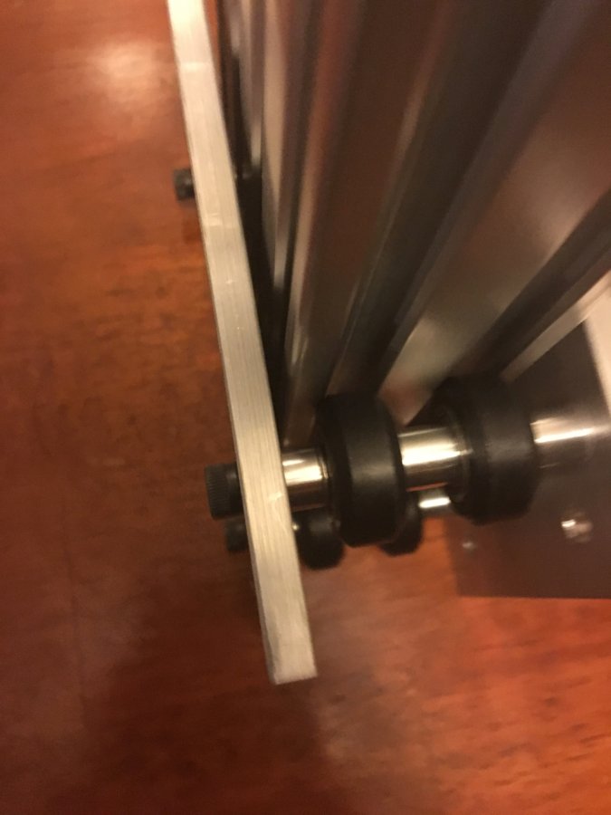
It took me a little to figure out the best was to attach the stepper motors to the c-beam. I ended up making plates that utilized the NEMA 17 brackets that came with my steppers. I added an additional spacer for the v-slot wheels so that the fasteners holding the stepper to the c-beam did not interfere with the motion of the mobile plate.
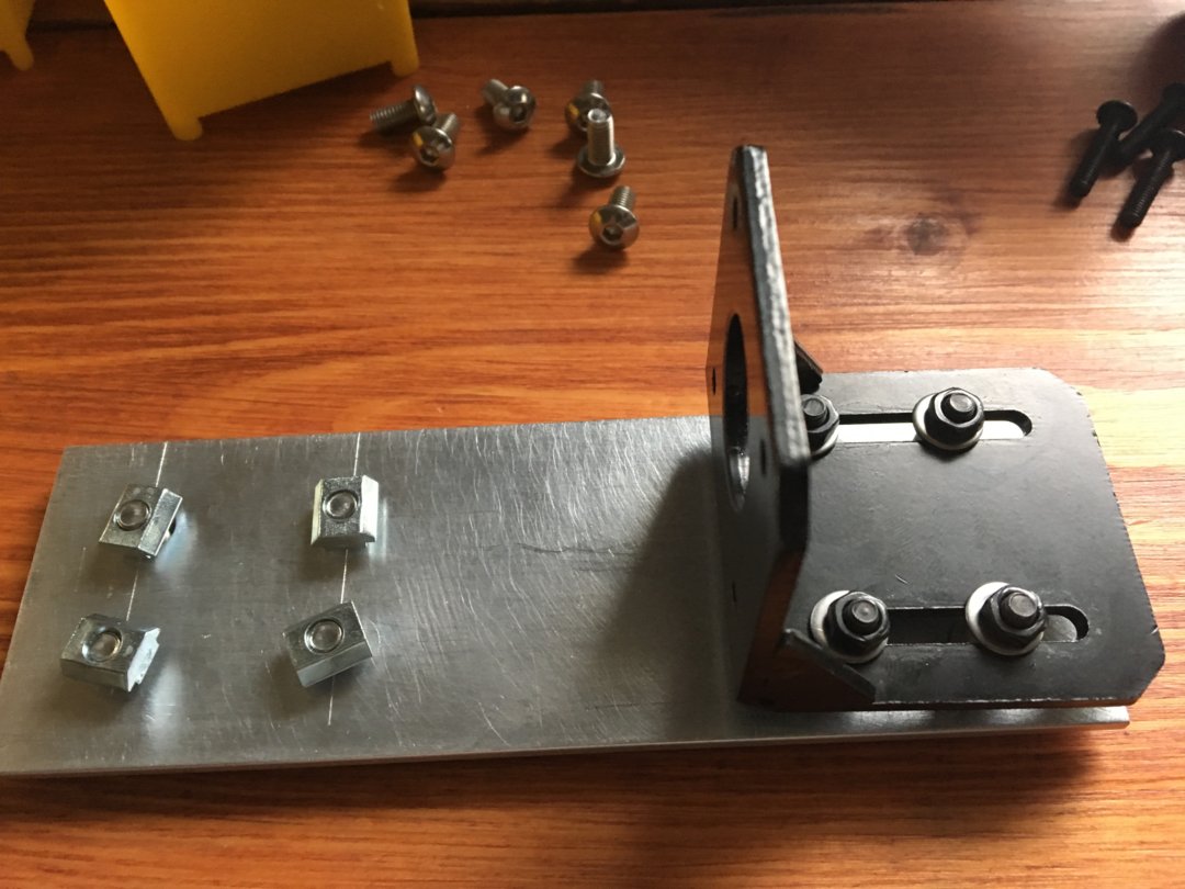
Completed Z axis and X axis.
I left the c-beam supporting the X and Z axis at full length because I planned to convert it to a moving gantry. Although to do that i would need to purchase more c-beam so it doesn't make much sense. However it seems to be fairly stable even standing on stilts.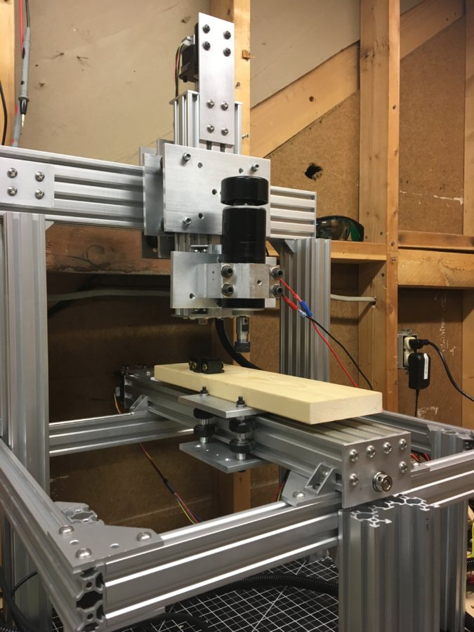
Usings small HFT wood clamps secured the tails of the 2040 v-slot to the exposed 2x4's of my room. This completely eliminated any wobble that I had. not sure what I am going to do when I drywall this room next year...
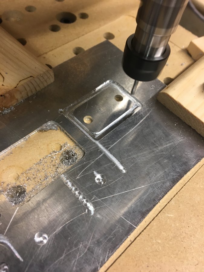
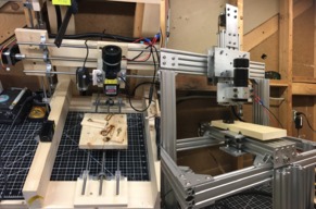
Initial test of aluminum cutting:
This worked better than i could have ever imagined for first test cuts. I had to optimize spindle speeds but ended up with a very reliable recipe:
0.125" 0.015" Rounded uncoated carbide endmill
300mm/min feed
0.2mm stepdown
Sharpie behind spindle speed potentiometer (... tachometer build in progress)
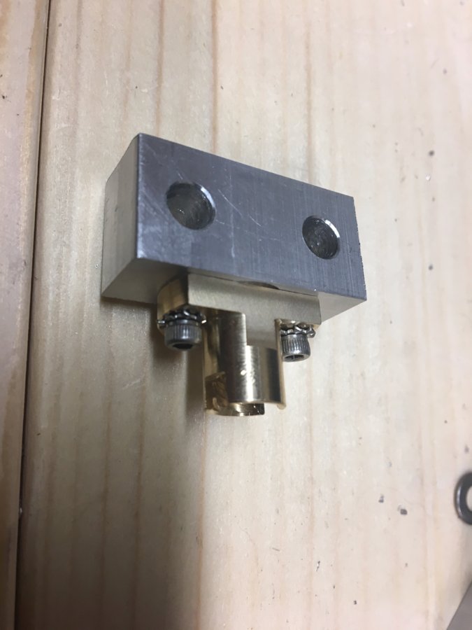
While sitting in my room working in Fusion 360, I heard a loud thud. The z-axis nut block had stripped through and spindle plunged into the aluminum plate of the Y-axis. Very thankful I didn't have a tool in the spindle. I had been utilizing PLA printed anti-backlash nuts, i was slightly worried about this in the Z-axis but it worked for some time so i put it out of my mind.
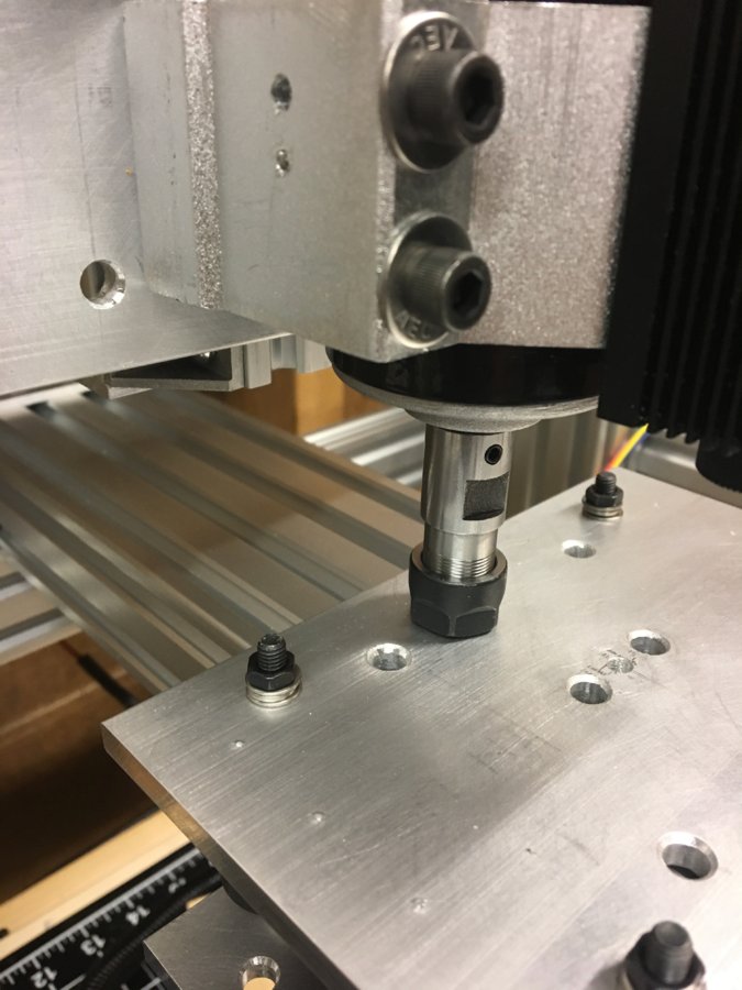
I ended up adding moving the anti-backlash nuts closer to the edge and adding the brass lead screw nut in addition to the PLA nut block for each axis. This worked very well and actually seemed to help reduce friction in the X-axis leading to faster travel rates. I cut aluminum blocks to match the thickness of the PLA nuts and shaved off one side of the brass nut to fit underneath the aluminum plates.
Electronics:
This is where i left off with Version 1:
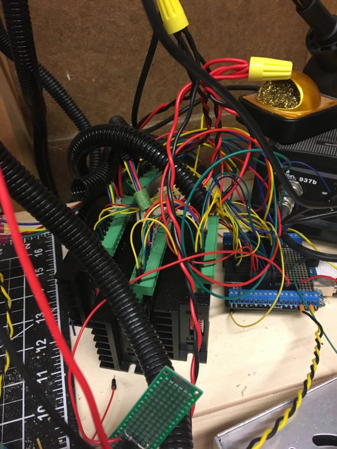
A complete mess but completely functional. The skinny protoboard in that got cut off is a relay to power the laser through GRBL's PWM spindle control.
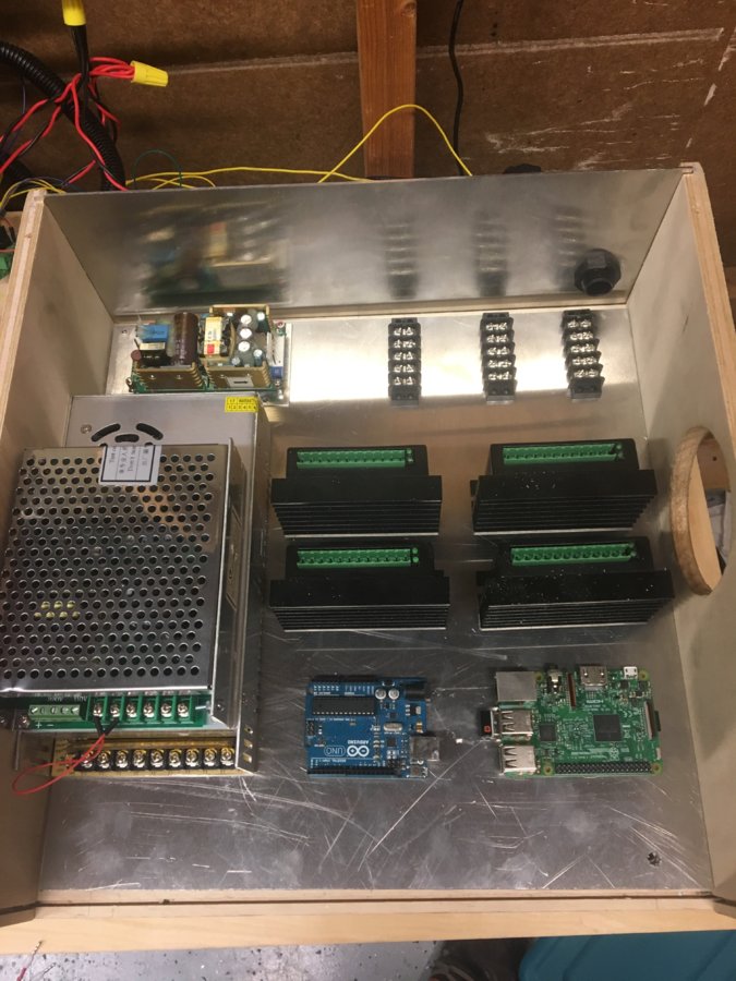
Since I left the machine on stilts I thought it would be cool to make an enclosure that sits underneath the machine. I used 0.5" plywood and 16ga aluminum to make the enclosure. The edges are slotted to secure the aluminum panels. Here is a shot of the layout planning:
A few changes and additions I am including:
E-Stop mushroom buttons that disables steppers and spindle. My previous emergency stop button was the 120Vac wall plug.
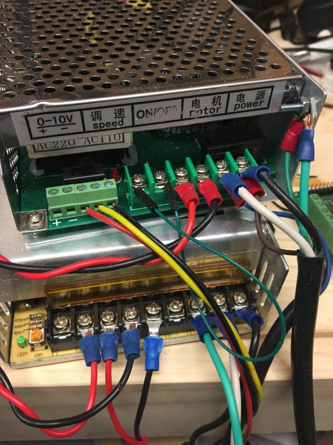
Dedicated 12Vdc power supply for laser. I was never too happy about having the lasers on the same power supply as 2 fans and 4 stepper motors. Not sure if the lasers were sensitive to and back emf generated. Didn't have any problems however it might just shorten the lifetime of the laser. Either way I salvaged a dual 5Vdc 12Vdc power supply that I decided would be used to isolate the lasers and eliminate the RPi wall wart. I also utilized a line power filter that was originally with the power supply.
Key switch. This is to keep my wife from using the machine. Just kidding, I salvaged this switch and it was the only on/off switch I could find in my salvaged stash that was rated at 15A.
You have probably realized by now that aside from CNC machines salvaging electronic parts is my other hobby.
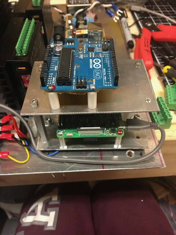
Decided I needed to stack RPi and UNO. Luckily I had just removed about 50 4-40 nylon stand offs from an old piece of medical equipment. I didn't realize how expensive those M-F standoffs are.
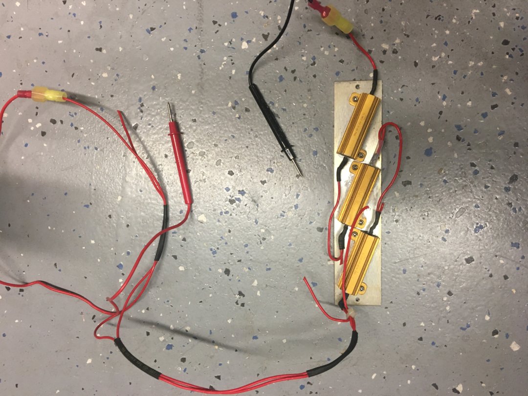
If anyone reading this has any problems with the same 0-100Vdc power supply for the cheap 500W spindle, be sure to safely discharge the large capacitor. this is what I used. Thhree 270Ohm power resistors in parallel, with a few snips converted to three resistors in series and a $3 set of multimeter test leads worked perfect.
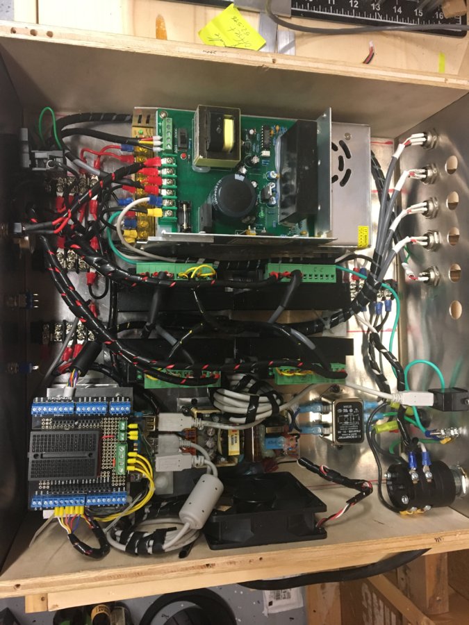
Finished control box.
Calibration and Alignment:
To be continued...
Hope you have enjoyed thus far.
ECNCML (budget mashup)
Build in 'Cartesian Style CNC' published by fctest, Nov 28, 2018.
This build summarizes my CNC milling and laser engraving machine conversion from a dimensional lumber frame and electrical mess to an all aluminum frame with a safe and well constructed (IMHO) control system with the resources I had available.
-
-
Build Author fctest, Find all builds by fctest
-
- Loading...
-
Build Details
- Build License:
-
- CC - Attribution - CC BY

