
Hello OpenBuilds community!
I am an intermediate DIY CNC’er at this stage. I started this journey about 5 years ago with a Grizzly Super X3 mill that I converted to CNC with a CNC Fusion ballscrew kit. Many, many thanks go to “Crevice Reamer” and “Priddy Shiddy” for the excellent write-ups on this setup. 5 years ago, there was much less information and resources available than there are now with OpenBuilds and many other DIY CNC resources. The SX3 does great for cutting parts within a 6”x14” window, but I have been searching for a larger work envelope solution for quite a while now.


I have been dreaming of ATC’s and eyeballing HAAS minimills and Tormach 770’s, but a planned move in the future make the debt and moving logistics untenable at this time for me. I was pretty intrigued by the price and envelope of the X-Carve when it came out, but the belt drives turned me away. Too much deflection and backlash for the metal-cutting precision I am accustomed to. Finally, in 2017, I stumbled upon the OpenBuilds C-Beam machine from a Ronin Energetics video on YouTube. I looked up the OpenBuilds site and immediately fell in love with the C-Beam X-large. The work envelope is perfect for some projects I have been dreaming up and the price is outstanding. Furthermore, there are many videos showing the aluminum cut quality that prove the practicality of the design. The portability of the design is another plus considering my current floor space limitations and future move. The SX3 needs to be moved with a cherry picker, which is cumbersome.
As I surveyed the design of the C-Beam XL, I noticed some aspects of the machine that I would change. The dual screws and steppers on the Y axis make me a bit uneasy. Steppers can miss steps independently of each other and that can lead to binding issues or misalignment. The Y axis support structure also allows a bit of cantilever from the bed under load from the spindle at the outer limits of travel.

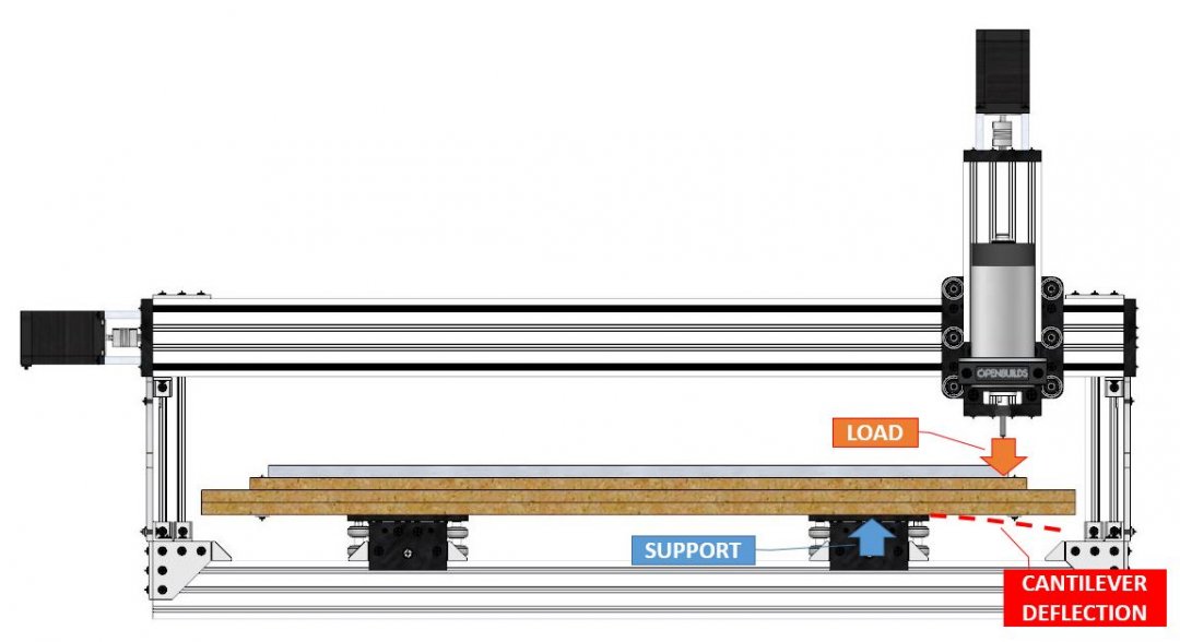
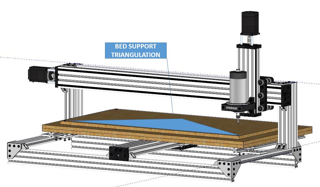
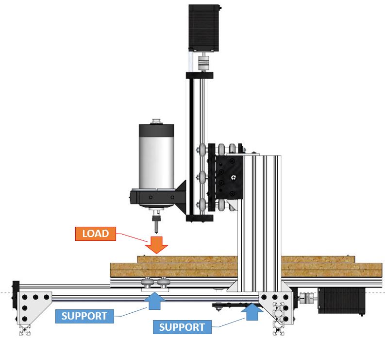
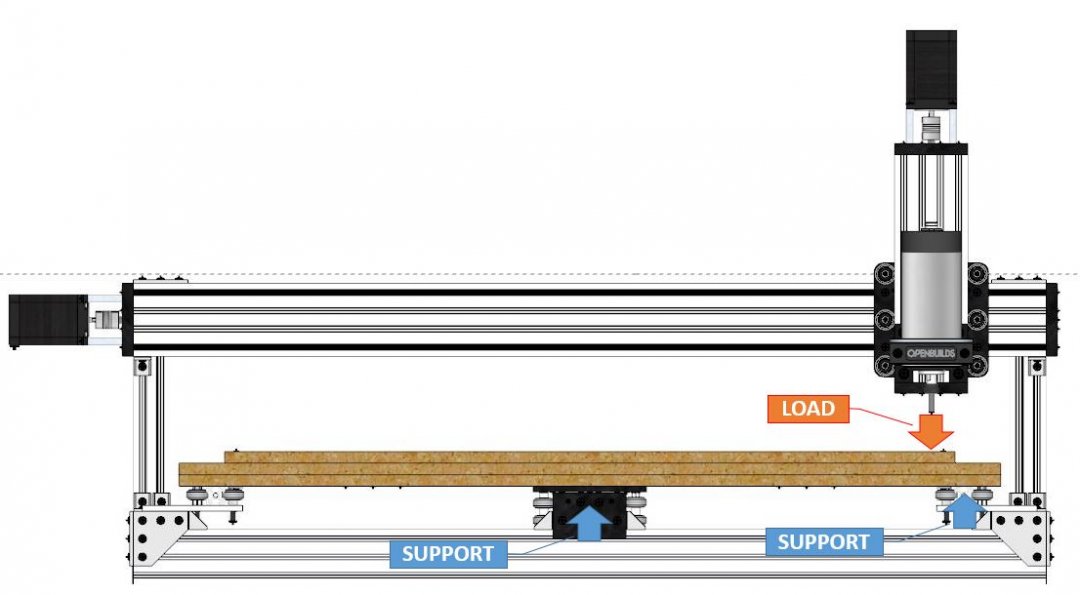
My concept for improvement of the design eliminates one lead screw/stepper from the Y axis to provide a single stepper for the Y axis. The edges of the bed will be mounted to some V-slot rail which will be retained to the frame by a rigid plate attached to the frame edges. The single middle gantry plate and the two edge carriages retain the Y axis so that the spindle can only contact the bed between triangulated supports.
I would love to initially assemble the C-Beam XL as sold in kit form and to a test cut in aluminum on the lower-right hand corner of the work envelope, then do the same cut on my proposed modifications for a direct comparison. Being the unflappable cheapskate that I am, I might opt to just purchase the individual components of my design, we will see.
For added rigidity, the X-axis C-beam can be easily braced against deflection in the Y-axis. A simple brace would triangulate the extended X-axis c-beam to the frame edges without interfering with any bed/spindle travel. This is easy rigidity with no drawbacks. I will likely fabricate my own welded or machined brace, but a standard Home Depot shelf bracket (illustrated below) with some spacers underneath would work quite well. Mine would tie into the horizontal frame member, the vertical frame member, and the X-axis C-Beam.
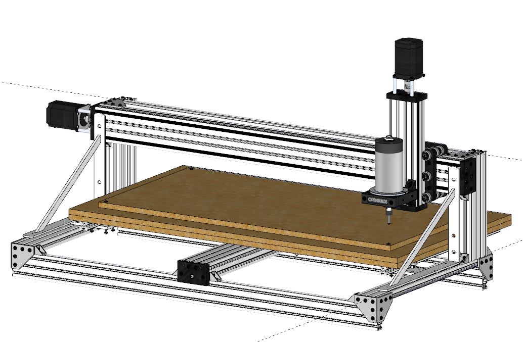
I have attached my Sketchup model of the concept. Please forgive my shoddy Sketchup model, this is my first time using it. I usually use SolidWorks and Fusion360.
5/13/17
Got all my parts in! I am going to be cutting my own gantry plates, however.
I recently made a simple power tapping jig for my production parts. While designing it, I also designed a way to tap my V-slot rails with the jig because I was dreading trying to tap all those holes by hand. Now I can use this jig to tap them with the impact driver! All I have to do is butt the squared off v-slot end up to the bottom of the tapping jig plate and rat-tat-tat-tat-tat away towards a square-enough tapped hole.


7/5/17 Update
Squaring up the extrusions is file-free in the mill
![IMG_3639[1].JPG](data/attachments/25/25397-4271d97dc6804b7b5c579e9a8159c154.jpg)
Milled up some rough gantry plates in .25" but I might make 2 more in .50" for extra rigidity on the Z and Y axis. Started assembling the frame parts this evening.
![IMG_3641[1].JPG](data/attachments/25/25398-a4eb919d14bef1ae56a7e1479bde9065.jpg)
8/7/17 Update
Made some modifications to the spindle mount that came with my spindle.
![IMG_3656[1].JPG](data/attachments/25/25914-b89fbd7a180ac136a3ebf813bd32ec35.jpg)
![IMG_3657[1].JPG](data/attachments/25/25915-b11ee45c4ff72d9b56abcd28990ae4c9.jpg)
The frame is just about all together. You can see the evolution of my side saddle design being implemented. I decided to add another 20x20 cross member to support the side saddle and allow easier adjustment.
![IMG_3675[1].JPG](data/attachments/25/25916-d8a148d119814bdef242f4e82028f8c1.jpg)
![IMG_3676[1].JPG](data/attachments/25/25917-2aa2bf798c10d99f1edd7bf048e64d60.jpg)
8/31/17 Update
Whoops, had my saddle plate bolts upside-down. Found out as soon as I tried to slide the bed on and had clearance issues. Here is the correct way they should go.
![IMG_3686[1].JPG](data/attachments/26/26361-0660f61b14e0a00f931af269b6a1d269.jpg)
Got the bed on! You can see that there is some aluminum angle that ties the side rails together to the middle and through the MDF.
![IMG_3693[1].JPG](data/attachments/26/26362-4646c4e09f7563244e84f75838862c12.jpg)
And we have motion!! After an annoying to track down grounding issue (the Arduino jumper wires are not sufficient gauge to feed signal ground all 3 drivers, had to use a larger ga. signal ground wire to the X axis and motor driver), I now have motion on all 3 axis! I am going the extra mile and putting limit switches on this one, so I will do my marker draw program after the switched have mounts and wires.
Here is a rough pic of my electronics after the first motion test. Yes,the infamous TB6560's DO actually work!
![IMG_3697[1].JPG](data/attachments/26/26363-576127a8367126b17cf8347230843310.jpg)
9/24/17 Update
Tested motion a little while ago and just never uploaded the video to YouTube. Here it is, still need to refine the accels to smooth them out.
Now I am working on the enclosure out in the garage.

10/1/17 Update
All finished with the enclosure, except still figuring out to how to stiffen the door a bit.
![IMG_3721[1].JPG](data/attachments/26/26820-64c47da6fc488232bfe738ca3f70c5bc.jpg)
![IMG_3722[1].JPG](data/attachments/26/26821-c32ccf94b16c9ff7217d01144be347f7.jpg)
Made a swinging stress relief for the X axis motor to prevent strain from constant movement.
![IMG_3720[1].JPG](data/attachments/26/26819-74a2c20a5cd120a88675d6d3fa19c644.jpg)
2/11/18 Update
It's done!
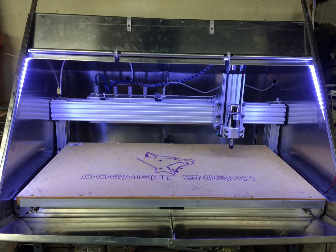

Dogmeat's Custom C-Beam XL
Build in 'X/Y Table Style CNC Mill' published by dogmeatk, Feb 11, 2018.
I love the C-Beam XL concept, this build is my custom version with the goal of increasing rigidity for metal milling.
-
-
Build Author dogmeatk, Find all builds by dogmeatk
-
- Loading...
-
Build Details
- Build License:
-
- CC - Attribution - CC BY
Reason for this Build
To cut large aluminum sheet metal partsInspired by
Moag, Ronin Energetics -
Parts list
Qty Part Name Part Link Comments 1 C-Beam Machine XLarge Mechanical Bundle http://openbuildspartstore.com/c-beam-machine-xlarge-mech... Link -
Attached Files:


