
OpenHardware Ultimaker For The Masses
10/3
The adventure continues. Changed to using a crane type lift for the Z axis. Had to mount it on one side instead of the customary rear. It uses the C-Beam concept - sort of. Also resized the frame, we are now at 16 1/2" wide, 17 1/2" deep, 16 1/2" tall with a 8x8x10 build area (51 linear inches)
10/2
More changes. Graduated up to dual extrusion, adding an extra filament driver. Since design leaves no room for mounting two part cooling fans, I've mounted 50mm blower type fans to the rear panel that blow air through 4mmOD x 3mm ID PTEF tubes that direct air jets to each nozzle.
.
Made a few changes over the 10/30 weekend. Changed the 4 corner upright from 20x20 extrusions to 20x40. That gives added strength, but also allows for s installing a false front and back for traveling that will enclose front door hardware and the backside filament driver. I also changed from 12"x12" build bed to 8"x8". If build area height is extended to 18" high, printer will still be less than 61 linear inches for air check-in luggage. Also moved the motor for running the filament driver to the floor with the other motors (an advantage of having a pulley/belt reduction instead of gears)
This build is essentially a DIY Ultimaker. Like Ultimaker, it uses linear rods and bearings on the X & Y axis - for both linear motion and rotational motion. While an axis may be moving linearly on a rod, that same rod may also be rotating to drive the similar motion on the other axis. This setup eliminates any movement of both the X and Y motors to achieve X/Y travel. The design limits the moving parts to merely the extruder hot end, 2 linear rods and two linear bearings - the key behind why Ultimaker has the reputation of being the fastest printer in the Desktop Class.
Linear bearings can be used for linear motion AND rotational motion. This design uses linear bearings for both linear and rotational motion - simultaneously. While an X carriage can be traveling linearly on it's linear rod, the same rod can also be turning, driving a belt to simultaneously move the Y carriage on it's linear rod.
Unlike the Ultimaker, which uses a crane system for lifting the build plate, this design uses four 8MM Acme screws to lift the four corners. This design is easier for DIY construction, and is infinitely tunable for leveling the build plate with the extruder.
http://3dwrx.com/openbuilds/bibox/anim.gif is a gif animation (this forum does not allow animation gifs)
The left bottom motor runs a belt to the fuschia rod at the rear top. As that rod spins it drives two belts synced to the fuscia rod on the front. Those belts are also attached to the Y axis carriages so that this motor effectively moves the Y carriages along the yellow Y rods while rotating the fuscia X rods. LIkewise, the right rear motor can move the X carriage.
One of the problems with making this design compact (height-wise) was placing both the X and Y rods on the same level, which also placed the drive belts for both on the same path crisscrossing each other. That was solved using 20 tooth pulleys on one axis and 32 tooth pulleys on the other. These are driven pairs so tooth size is irrelevant since both axis drive pulleys are on the respective motors.
The second secret to the Ultimaker's speed is the geared filament drivder mounted on the printer's rear panel. Ultimaker uses 3:1 gearing. I prefer aluminum pullys and belt for longer wear. My 50T:16T gearing produces 3.125:1 ratio. Below are pics of it's assembly
![[IMG]](proxy.php?image=http%3A%2F%2F3dwrx.com%2Fopenbuilds%2Fbibox%2Fxtrdr%2FUntitled1.png&hash=8eb89123b298f418ae985372278c2110)
![[IMG]](proxy.php?image=http%3A%2F%2F3dwrx.com%2Fopenbuilds%2Fbibox%2Fxtrdr%2FUntitled2.png&hash=237fd9b49c2d96acabea56a52fcce340)
![[IMG]](proxy.php?image=http%3A%2F%2F3dwrx.com%2Fopenbuilds%2Fbibox%2Fxtrdr%2FUntitled3.png&hash=f1eaee320e610466d1034245266d7306)
![[IMG]](proxy.php?image=http%3A%2F%2F3dwrx.com%2Fopenbuilds%2Fbibox%2Fxtrdr%2FUntitled4.png&hash=d0a7b17bb649f11efa67a4343eecf8d8)
![[IMG]](proxy.php?image=http%3A%2F%2F3dwrx.com%2Fopenbuilds%2Fbibox%2Fxtrdr%2FUntitled5.png&hash=d988f66300b2cd6ddcad8e892cb8d085)
![[IMG]](proxy.php?image=http%3A%2F%2F3dwrx.com%2Fopenbuilds%2Fbibox%2Fxtrdr%2FUntitled6.png&hash=deeb87ad8365983da2badf089bbd1a92)
![[IMG]](proxy.php?image=http%3A%2F%2F3dwrx.com%2Fopenbuilds%2Fbibox%2Fxtrdr%2FUntitled7.png&hash=01dea47d817209fed1e541494c682108)
An SKP of the design can be downloaded http:///3dwrx.com/openbuilds/bibox/diy-ultimaker.skp
This is a design in progress. Estimated BOM for building this DIY Ultimaker is less that $500 - a fraction of buying an actual Ultimaker with the same performance.
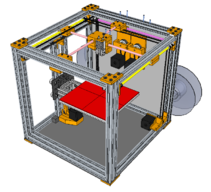
DIY Ultimaker
Build in 'H-Bot and Core XY' published by Keith Davis, Nov 4, 2017.
This design should give the same performance as the high speed Ultimaker since it uses a similar ultra-light X/Y concept which eliminates any movement of both the X and Y motors to achieve X/Y travel.
-
-
Build Author Keith Davis, Find all builds by Keith Davis
-
- Loading...
-
Build Details
- Build License:
-
- CC - Attribution NonCommercial - No Derivs - CC BY NC ND
-
![[IMG]](proxy.php?image=http%3A%2F%2F3dwrx.com%2FLZ%2Fimgs%2Fcrane1.png&hash=3400f6cce52bc8b52c034336fd916fd7)
![[IMG]](proxy.php?image=http%3A%2F%2F3dwrx.com%2FLZ%2Fimgs%2Fcrane2.png&hash=685491f96f7c735d68a3ab0ef17a09aa)
![[IMG]](proxy.php?image=http%3A%2F%2F3dwrx.com%2FLZ%2Fimgs%2Fcrane3.png&hash=6a9ef544e8406bdd0976acd896b94b09)
![[IMG]](proxy.php?image=http%3A%2F%2F3dwrx.com%2FLZ%2Fimgs%2Fventuri1.png&hash=0199ded73da3ee4aecf9d6d58b90c28c)
![[IMG]](proxy.php?image=http%3A%2F%2F3dwrx.com%2FLZ%2Fimgs%2Fventuri2.png&hash=4cf2c41cc17c191570a7a0ae89314b91)
![[IMG]](proxy.php?image=http%3A%2F%2F3dwrx.com%2Fopenbuilds%2Fultima%2F1.png&hash=767096b8f383dcf28245df05054ee1f3)
![[IMG]](proxy.php?image=http%3A%2F%2F3dwrx.com%2Fopenbuilds%2Fultima%2F2.png&hash=8ea8be157c821a5f44d0d1d05c5fbcfd)
![[IMG]](proxy.php?image=http%3A%2F%2F3dwrx.com%2Fopenbuilds%2Fultima%2F3.png&hash=5d33031005428eea94f461e99e7b50d2)
![[IMG]](proxy.php?image=http%3A%2F%2F3dwrx.com%2Fopenbuilds%2Fbibox%2Fa.png&hash=4c22fa6caeda03b7fc4ce409a6acb50d)
![[IMG]](proxy.php?image=http%3A%2F%2F3dwrx.com%2Fopenbuilds%2Fbibox%2Fb.png&hash=c1c421b4fa79ea11f43bbb2ed1a04633)
![[IMG]](proxy.php?image=http%3A%2F%2F3dwrx.com%2Fopenbuilds%2Fbibox%2Fmaster.png&hash=e6bc64285be94c1643fab06cfbed6ff1)
![[IMG]](proxy.php?image=http%3A%2F%2F3dwrx.com%2Fopenbuilds%2Fbibox%2Fpulleys.png&hash=69d344d8eec7c99e78b5f9e4f51bab56)
![[IMG]](proxy.php?image=http%3A%2F%2F3dwrx.com%2Fopenbuilds%2Fbibox%2Fxtrdr%2FUntitled8.png&hash=c666280bba02c47566e474f9ef2890b5)