*Move to resources*
I helped a friend build a modern controller for his laser cutter a year and a bit back, and in the process, I got to know DIN rails a little. When I found them, I had already bought power supplies and so forth, and had mounted them to a board, but still, I used the DIN rail combined with terminal blocks to do interconnect. I think it helped. The terminal blocks are just a little wider than the wires themselves, so you can fit MANY into a linear foot of DIN Rail, and they have surprisingly high power ratings (the ones I bought were rated to 200V 60A, IIRC). You can also get units with an integrated fuse, and you can get busbar hardware that bridges several terminals together. This was all pretty sexy. The wiring became less rats-nest-ish, and was easy to rearrange without really touching the devices themselves. I was really just moving jumpers around, when needed.
I really liked the whole thing, but a few weeks ago, I ran into a product called the DINrplate ( DINrPlate ) and I thought, I can mount the pi (that ran laserweb), the arduino (that ran GRBL), all the power and signal wires, and I knew I could get DIN mounted power supplies. Suddenly, my next electronics box was looking MUCH neater in my head. Just grab a meter of DIN rail, maybe cut it in to 3 or 4 lengths, and bolt them down to something flat. There's plenty of electrical boxes built around DIN rails, and I know some european countries use circuit breakers that are DIN mounted too.
There's just 2 things that I didn't like:
1) the stepper drivers that openbuilds sells (and many other places, too) have no standard DIN mount hardware. It's not hard to make one, but off the shelf would have been nice.
2) I was thinking that I would attach DIN rail to t-slot in some places, if I wasn't putting everything in an electrical box. But then I thought "Why? I could design a 20mm t-slot quick release, and just mount everything directly to the t-slot. "
I'm back to needing something like the DINrPlate, and I'd have to make my own terminal blocks etc, and the DIN power supplies would need an adapter... but if I design it all, it'll be easy to laser-cut, mill, bend and 3D print parts. I've got the DIN gear to act as a reference, so it should all be pretty quick.
I have yet to draw anything on paper or in CAD, so this is just a manifesto of sorts. I'll fill it in as I go.
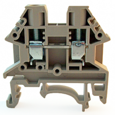
A terminal block for connecting 2 wires, integrated DIN clip on bottom. This particular design won't allow the use of a busbar, which is odd...
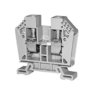
This terminal block has the threaded hole to add the busbar.
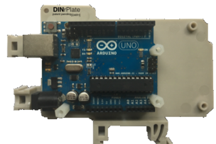
An Arduino Uno mounted on a DINrPlate.
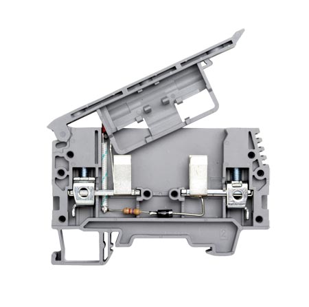
a fused terminal block. Note the resistor, diode, and very hard to spot LED to indicate a failure. The fuse holder door thing also has space to hold a spare fuse.
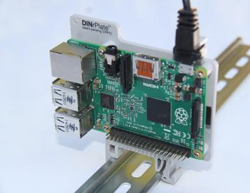
A Raspberry Pi on a DINrPlate.
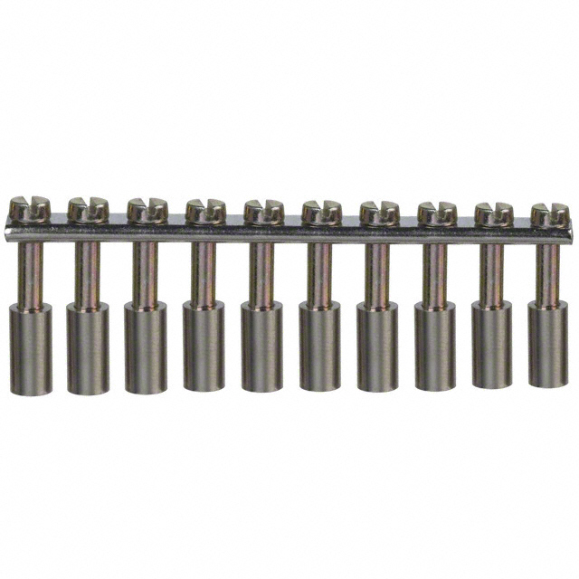
This is a busbar for the terminal blocks. This would allow up to 20 wires to be bussed. You can cut them to the length you want
---
2018-09-20T20:00:00-04:00
"It should all be pretty quick". Famous last words!
That last posting was written in May, and now it's September, and nothing yet!
Anyhow, continuing in my rambling blog-ish style...
A week ago, I watched a video by MakeAnything, in which he demonstrated how he was making his 3D printing timelapses. ( ). In there, at about 4:30, he did something somewhat similar to hold a remote, and it got me energised again.
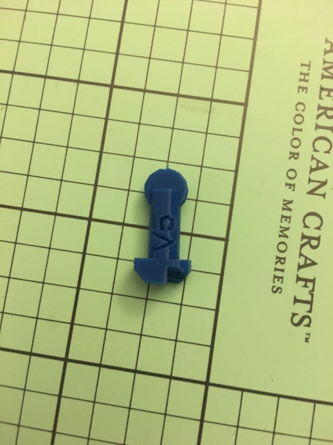
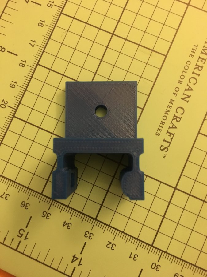
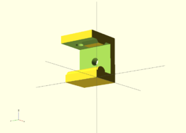
On the bus to work this morning, I sketched out my idea for a clip, and then after work I made a first stab at it in OpenSCAD. Here's the clip!

There's two 5mm holes (one on top, one on the side) where the clip can be bolted down.
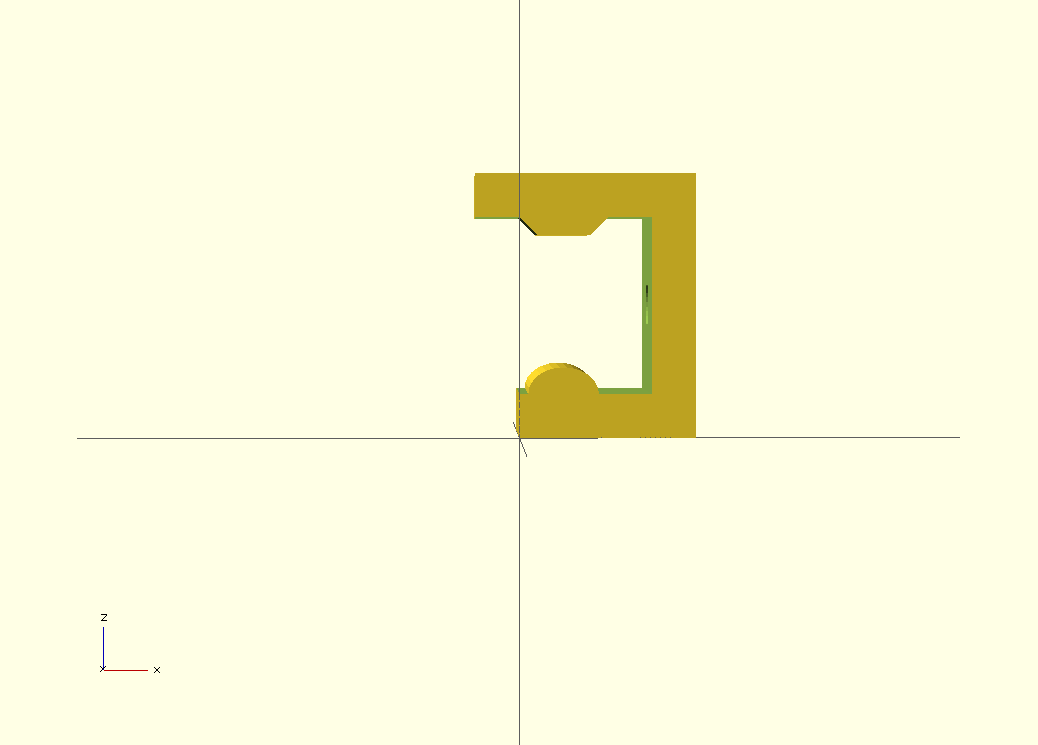
In theory, the top will be a bit more rigid and fit snugly, while the bottom should slide+flex in. Before I print these and test, I'm going to build in some reliefs for a living hinge, to give the bottom section a bit more flex.
----
2018-09-23T23:30:00-04:00
First, a mini review: I just acquired a Prusa i3 MK3 kit, and it kicks ***.
I printed the clip in PLA (fast low quality, standard infill). You know those lessons you need to relearn once a year or so? In this case, it's that if a part is 20mm, the thing that attaches to it needs to be a little bit bigger.
In other words, it's too tight a fit.
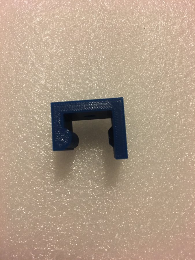
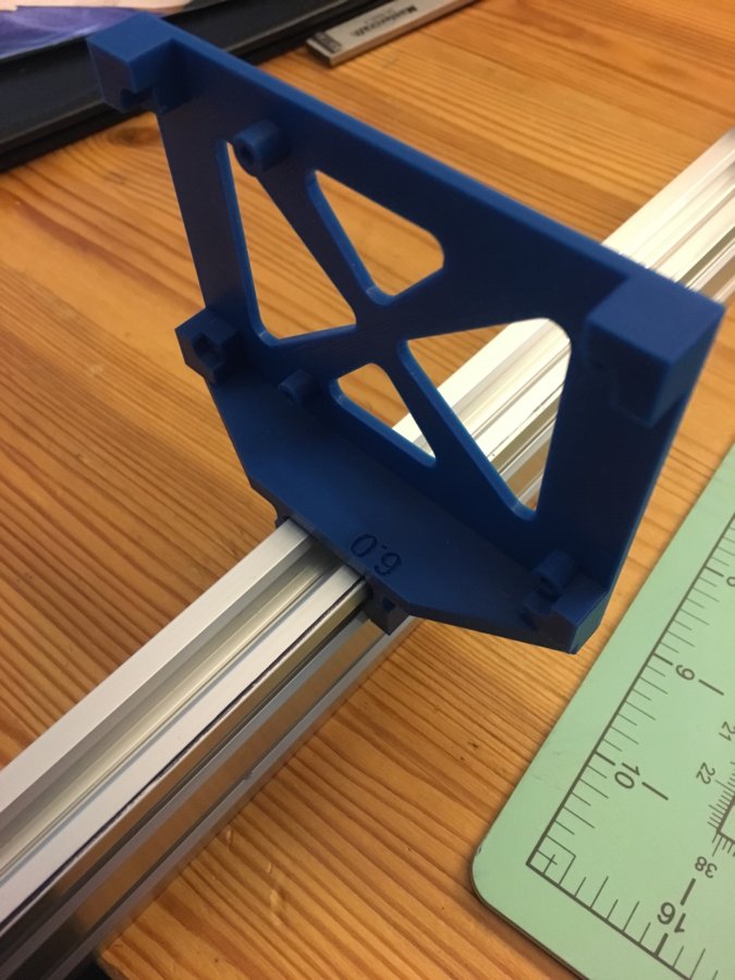
Here it is on some vslot2040, after some percussive persuading.
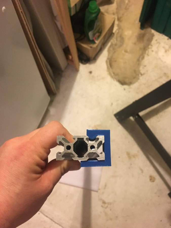
- - - -
2018-09-30T23:30:00-04:00
I tried to file the printed part to fit, but it was too hard to make any progress. After lots of sketching and so forth, I started changing the model. I gave a little clearance, shortened the top, and put some reliefs in to create some flex. In the process, I commented out the code that generated the chunk that keyed into the top of the ballot, and forgot about it. When I printed it, I figured it was a big loss but tried it anyhow. It worked anyhow!!! It was a tight fit, so I made the rounded key a bit smaller, and now it’s a very satisfying click into place. Not too much effort, but not too easy remove either.
Seems I have video, but not photos. I’ll fix that tomorrow...
----
2018-10-03T23:50:00-04:00
Ok, so I haven't gotten around to posting photos yet, but I need to post! Here's what I've got:
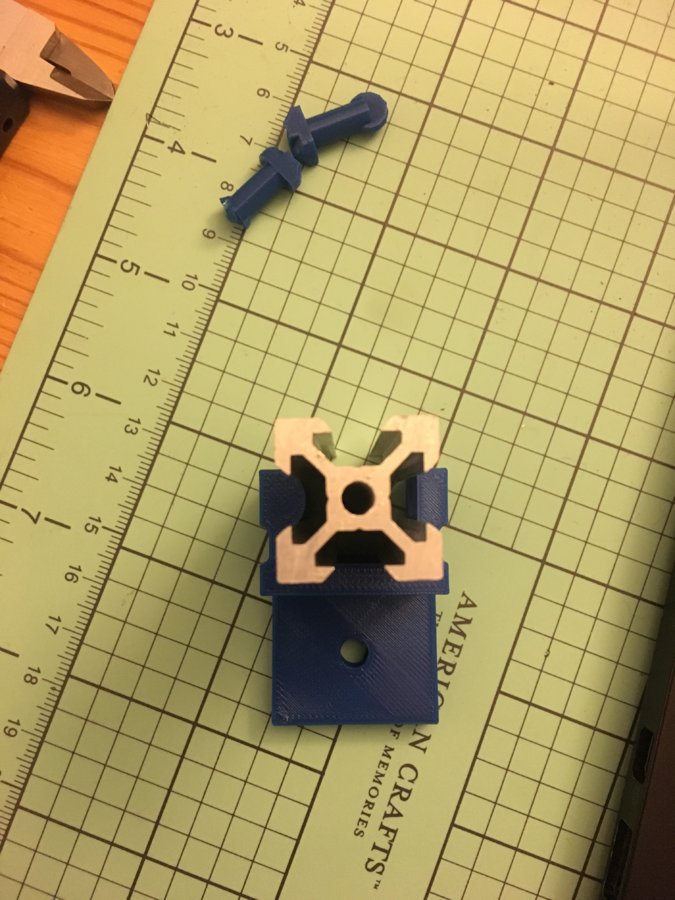
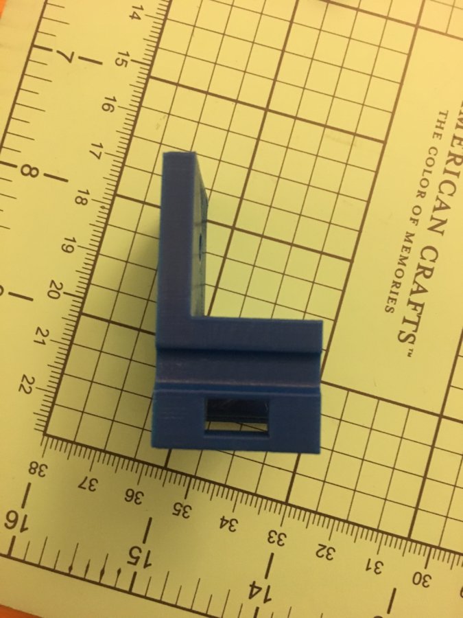
1) clip works really well. I've got a loose fit, so it slides easy, but it won't fall off (unless it slides off the end). I've added a flange so I can attach things to it. I've changed the hole intended to bolt it in, to a rectangle. I got the dimensions wrong on my first print, but you'll be able to use drop-in tee nuts with it.
2) the thing I'm really excited about is that I made a 3D printed drop in thing...It's not a nut, it's more of a cam-lock. Push it into the v-slot and turn 90 degrees and it's locked in! The post on it is 5.8mm, with a bit of a handle thingy to make it easier to grip. They take about 10 minutes to print on my printer.
I'm going to do a reprint of the clip to verify I got the size right, then make a plate+clip that a Pi attaches to, then do the same for an arduino...
After that, I need to figure out what my terminal blocks will look like.
----
2018-10-07T01:47:00-04:00
I reprinted the clip, and the cam-lock-nut-mc-thingy fits pretty well, but since it's a rectangular hole, once locked the clip has about 5mm of movement. net iteration TBD!
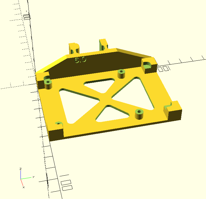
In the meantime, I designed a pi-plate. The design was inspired by Raspberry Pi Plate by codevalley and Raspberry Pi Plate by EhisforAdam , although mine is completely original SCAD work. Those are CC BY3.0 and CC BY-SA 3.0 respectively, FYI.
I've got a longer print going right now, so I'll print this tomorrow. Happy Thanksgiving, my fellow Cannuckians!
----
2018-10-07T13:07:00-04:00
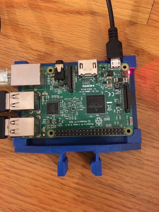
Printed the pi-plate. It looks good! I forgot to add back in a hole for a bolt or cam lock, and I accidentally tweaked something so that the fit on the v-slot is loose, but the Pi3B+ fits perfectly.
----
2018-10-14T22:20:00-04:00
So much progress.
I made plates for my power supplies, and arduino UnoR3, and my BigEasyDriver (a stepper driver).
They're all laid out more or less the same, but different dimensions. I kept getting them confused and was screwing them up as much as not, so I wrote a python program!
The program reads an XML that defines the board, and generates a scad file. Then, I generate an STL with OpenSCAD, then slice&print. Tweaking the XML is way less error prone!
Also, I started designing a terminal block. I started off emulating the commercial units, but in conversations with Ron, we itterated a few times, and have moved on to a unit that will use a cam to lock the wires in, as well as being pretty simple to gang together to build 4,6,8,10,etc terminal blocks. I haven't designed it yet, but it will need an isolator/spacer to prevent blocks from shorting when they shouldn't.
DIN 35mm -like quick clip for 20mm extrusion
Build in 'Everything Else' published by MTO, Oct 14, 2018.
A half baked idea for mounting electrics and electronics using a 35mm-DIN-rail-like mounting.
-
-
Build Author MTO, Find all builds by MTO
-
- Loading...
-
Build Details
- Build License:
-
- CC - Attribution - CC BY
-
Attached Files: