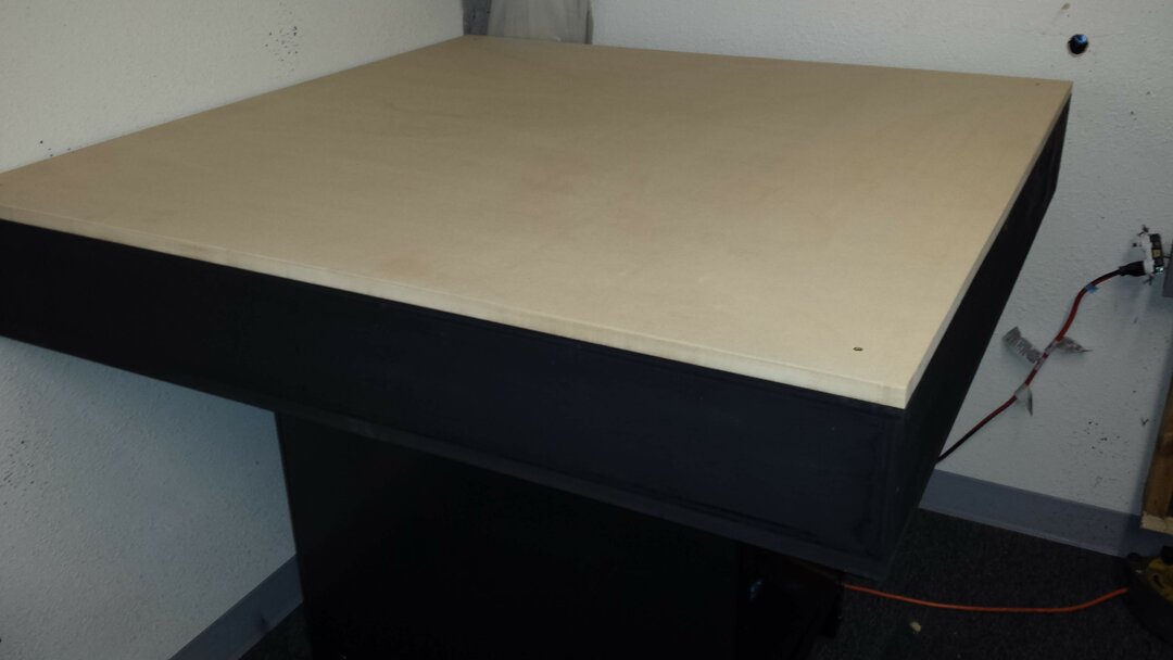
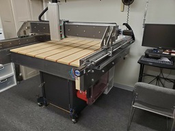
I started this project by building a 4'x4' torsion box platform and mounted it on an old metal base cabinet I had.
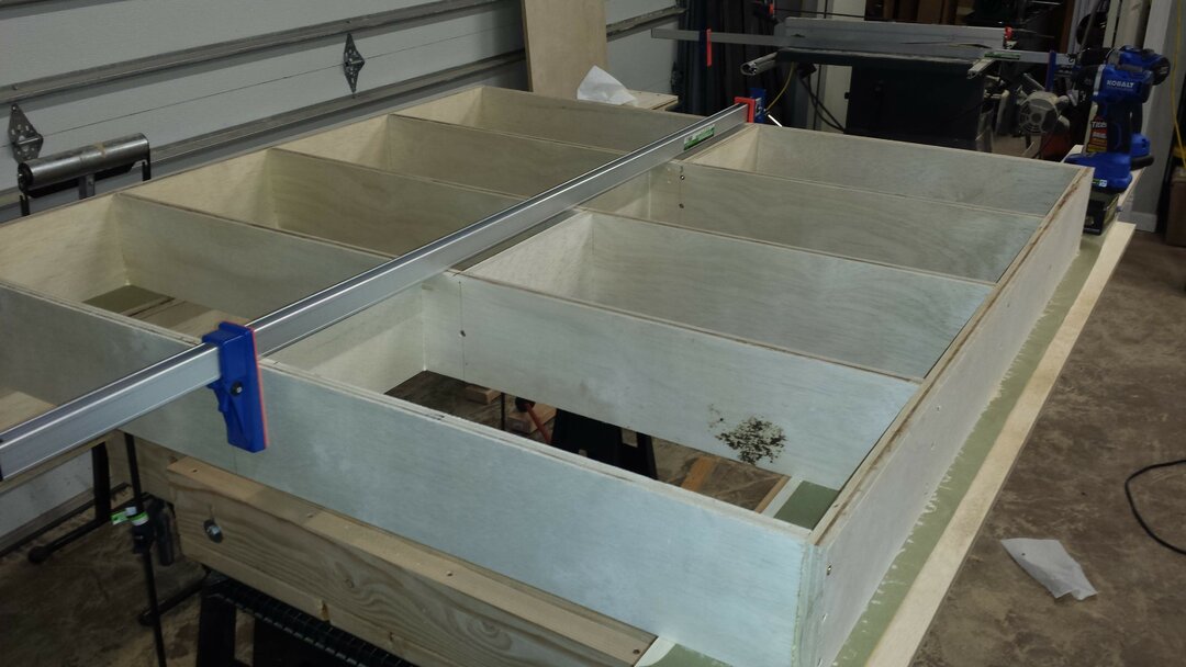
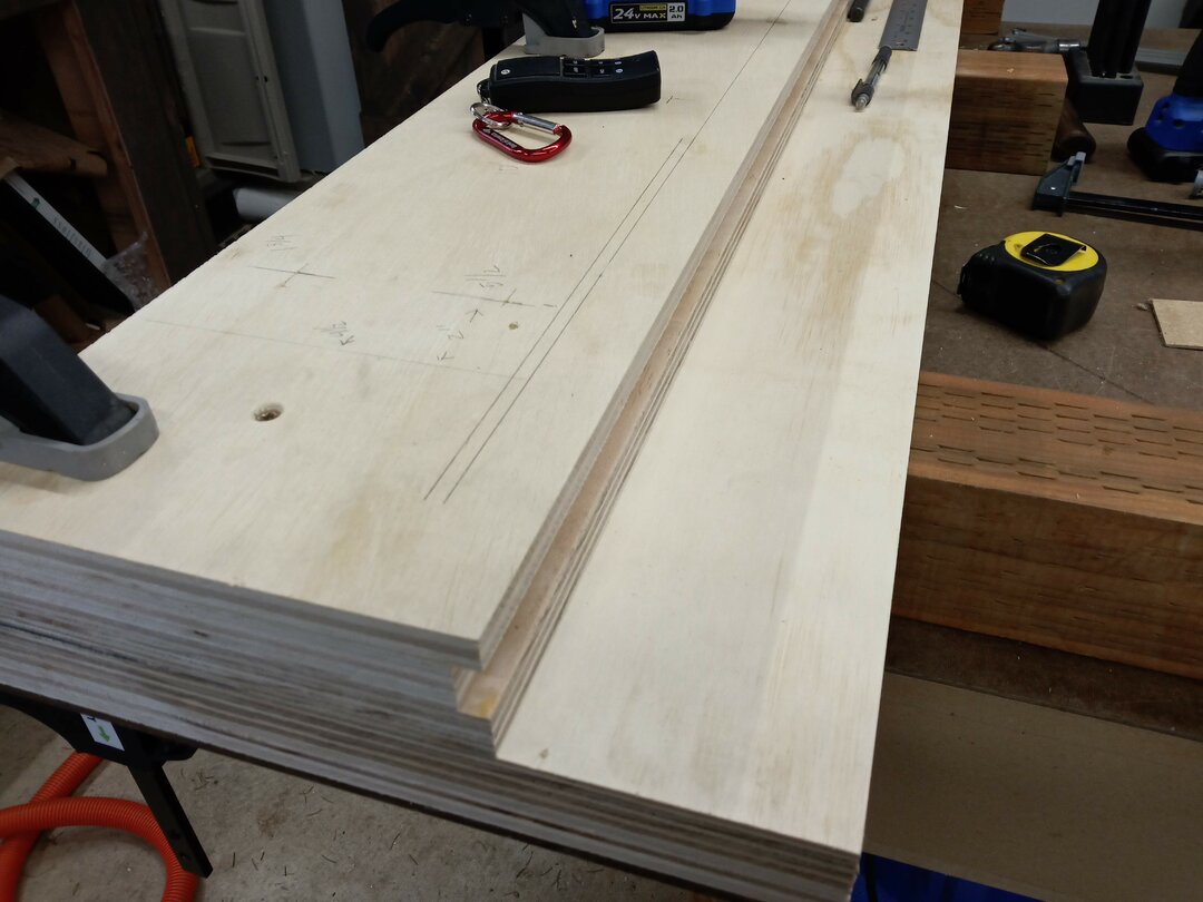
I decided to go with a Cartesian style. Since my welding is not up to snuff I decided to start with wooden Y beams. I built these beams much the same way glulam's are made by gluing all the boards together first, then clamping them down to a flat surface so they would dry flat, and finally screwing a bunch of screws through them.
I then attached a 1/4" x 1' x 5' steel plate on the outside of each Y beam. I then drilled 10 mounting holes through the Y beams and into the torsion box on each side. I then ran heavy duty bolts through with large fender washers, locking washers and lock nuts. But I only tightened the outside bolts to start.
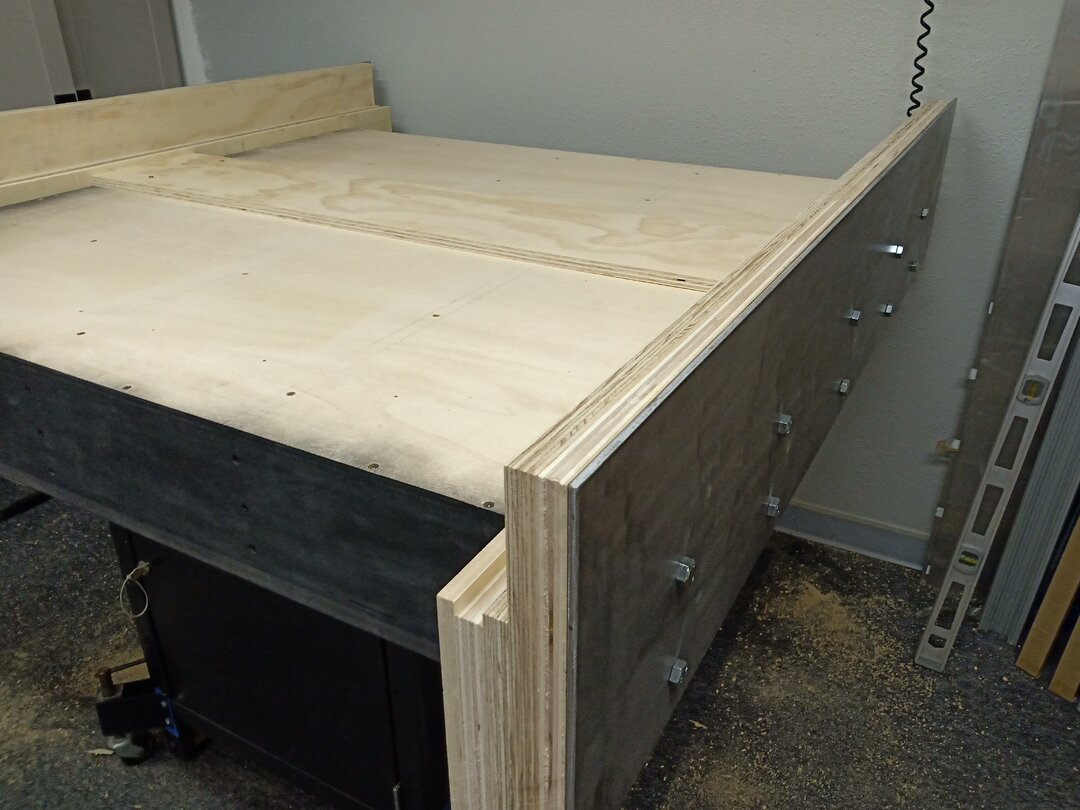
I noticed once I installed the Y beams that the side walls of the torsion box were not all that straight. I had small gaps that ran the length of the beams. So I decided to fill the gaps with a strong resin.

Once the gaps were dry I then was able to tighten the bolts.
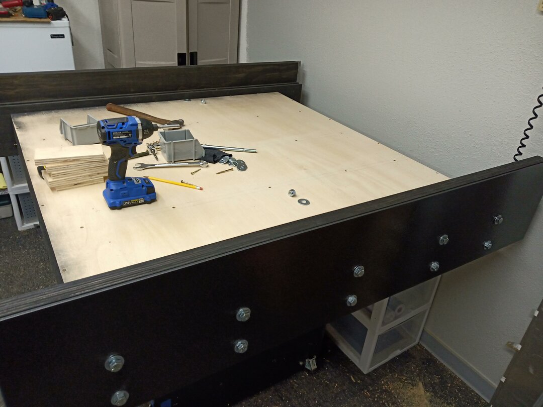
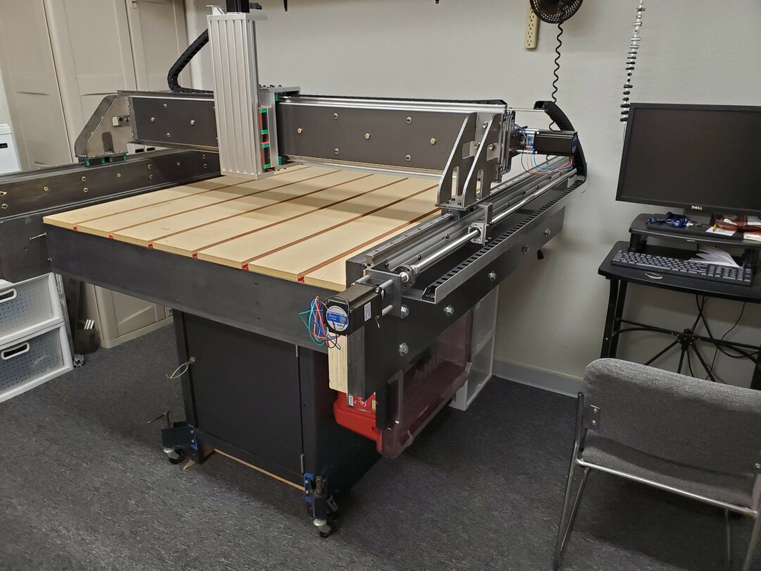
Now I can start mounting the 20x80 extrusions for the Y axis. I mounted these on the outside of the steel plates. These are bolted all the way through the extrusion, metal plate, and 3" of plywood.
Note: This is one area that I feel I can improve/upgrade how these are mounted. I feel that upgrading the bolts would make it better.
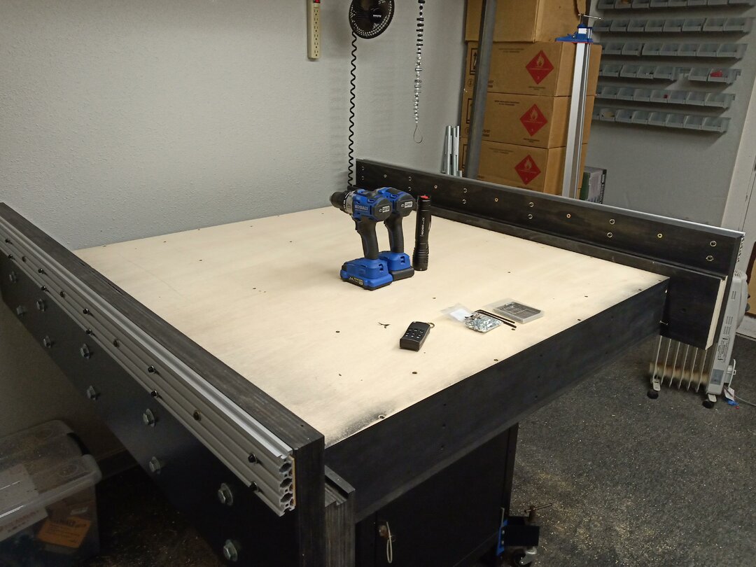
Next I installed the linear rails on the Y axis.
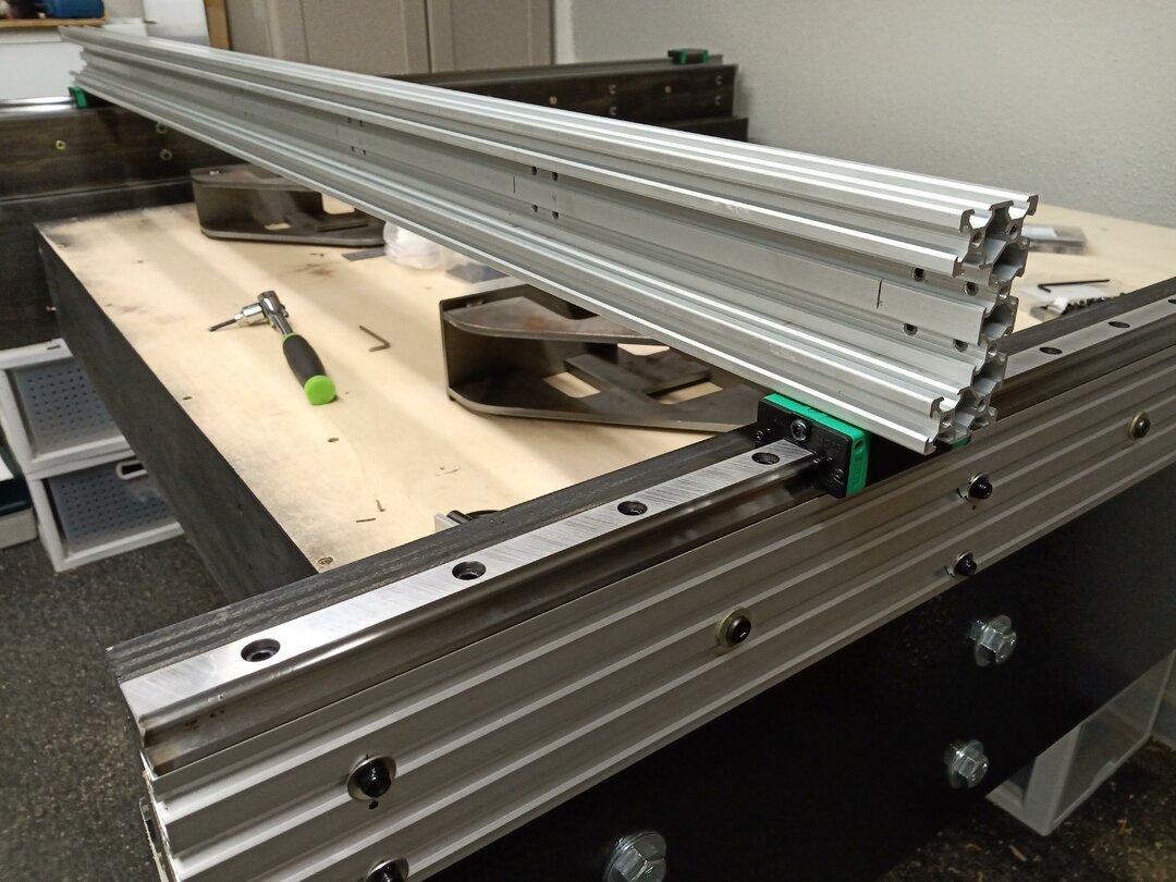
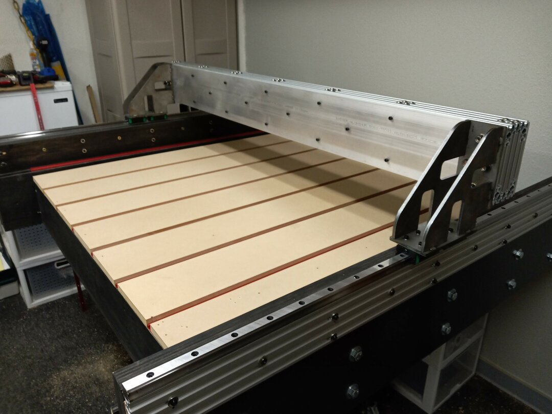
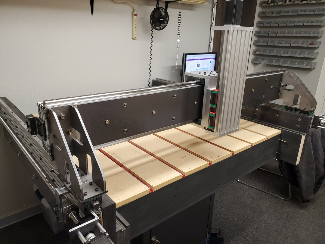
Once the linear rails were installed and carefully aligned/leveled I then started working on the gantry. Here you can see the 1/4' laser cut and welded uprights I am using as well as the basic skeleton of the X axis. More pics below on the construction of the X axis.
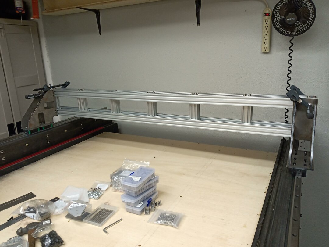
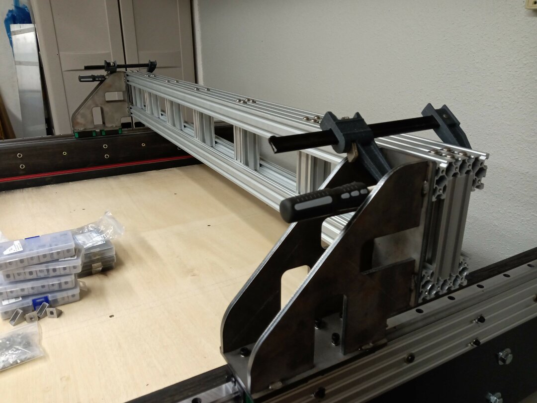
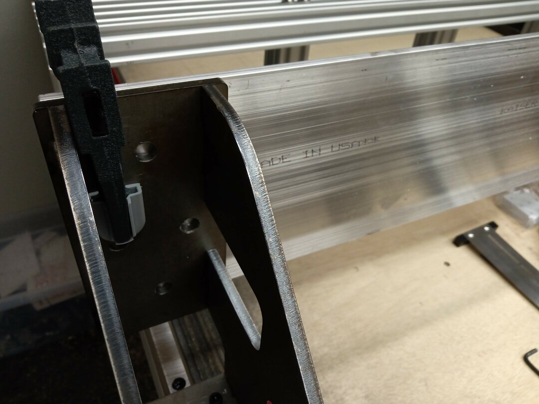
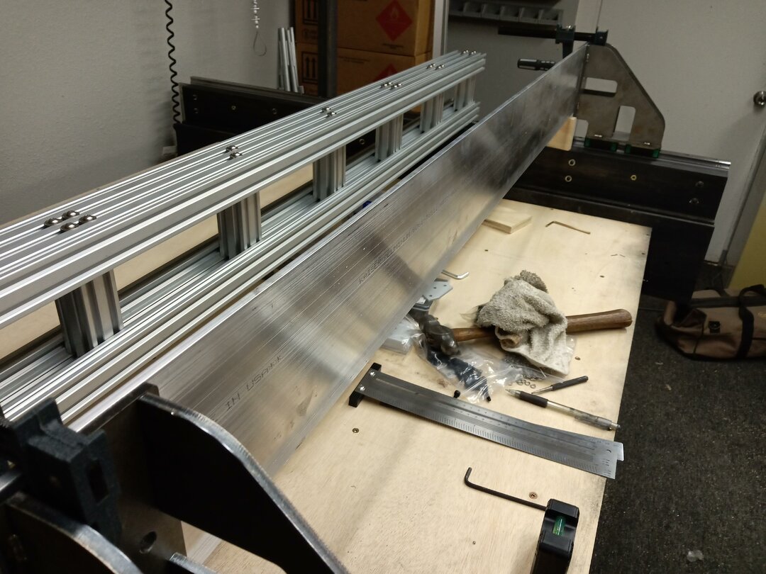
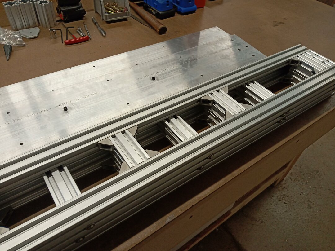
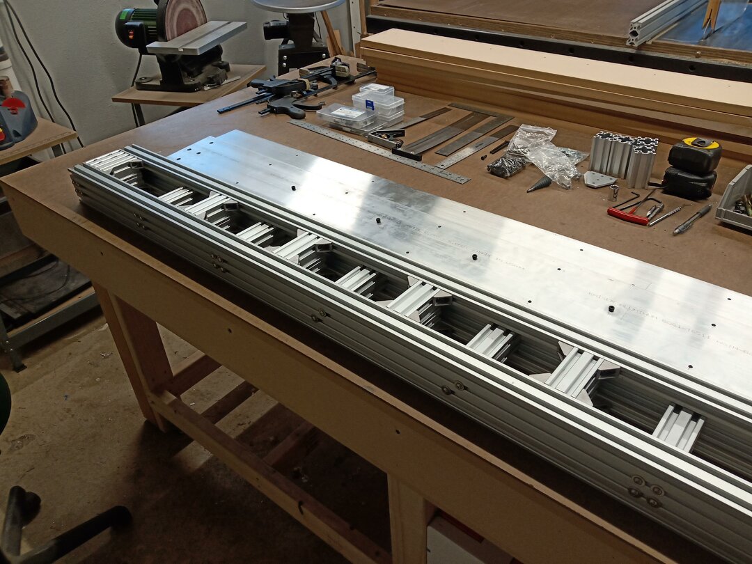
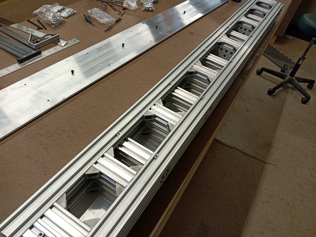
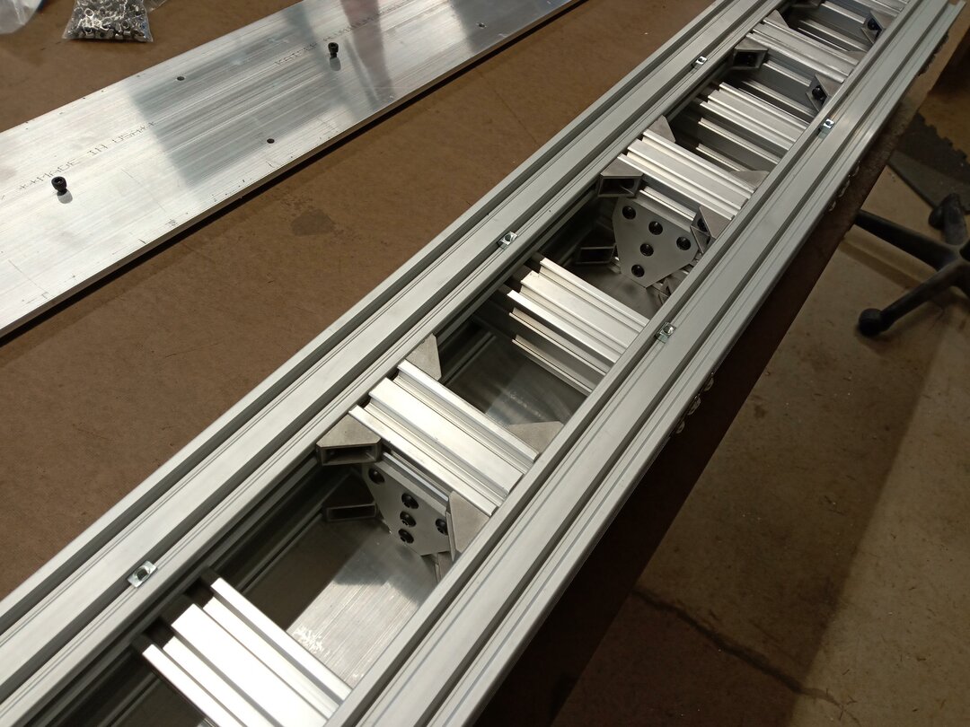
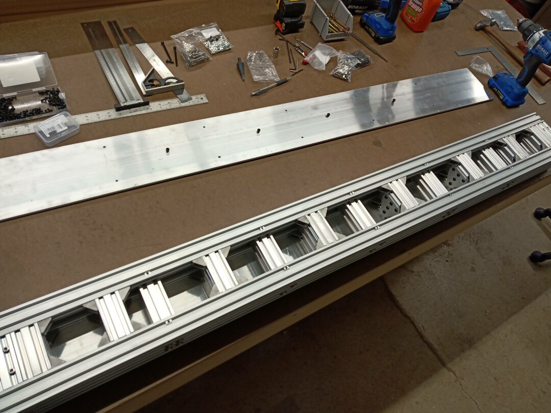
The X axis/gantry beam is constructed of two v-slot C-beams that sandwich a web of 40x40 v-slot extrusion pieces that are attached and screwed together from many angles. The completed beam is then sandwiched between two 1/4" x 6" x 60" 6061-T6 Aluminum Bar Sheet Plate and bolted all the way through as well as attached via M5 t-nuts. This has made a very heavy and sturdy beam.
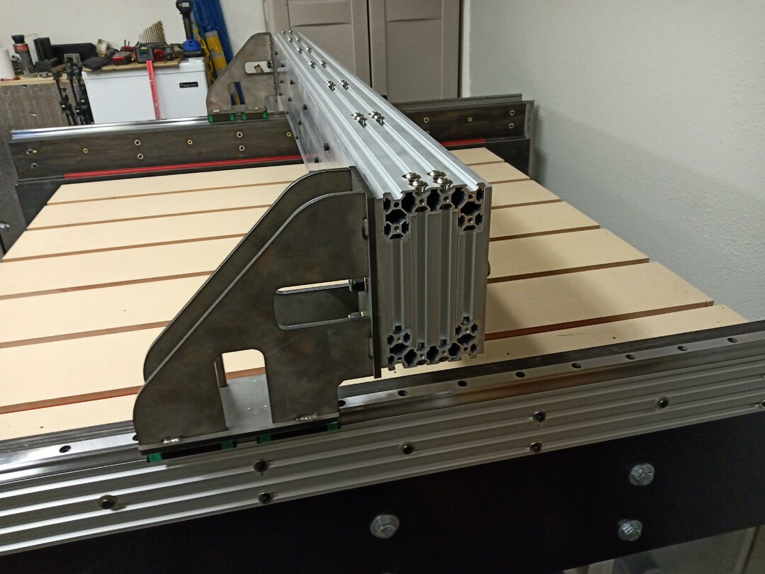
You will also see that I mounted the X axis beam to the uprights using 4 heavy duty bolts that go completely through the beam.
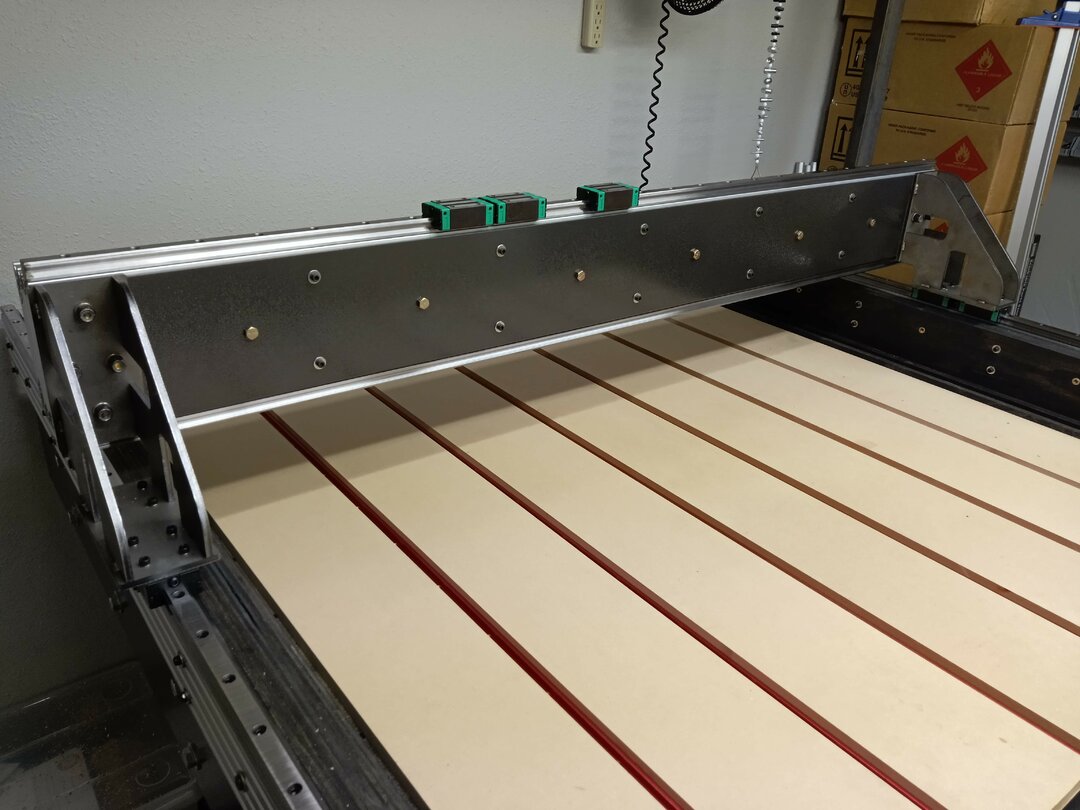
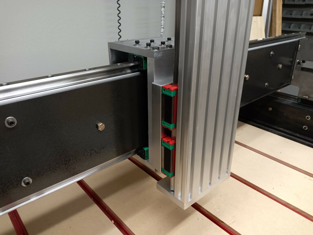
Next I installed the linear rails on the X-axis

Now it was time to work on the Z axis. I bought a pre-built Z axis assembly but needed to figure out how to mount it. I decided to build a cage that was supported all the way around the gantry. This would give it structural support and provide a way for me to attach the ball screw to the Z axis assembly for the X axis movement.
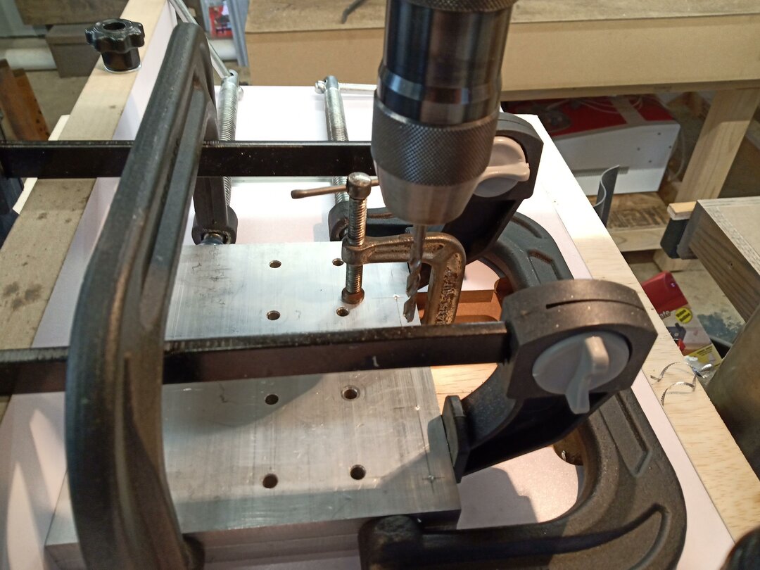
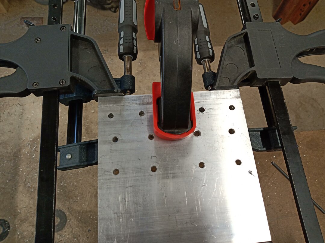
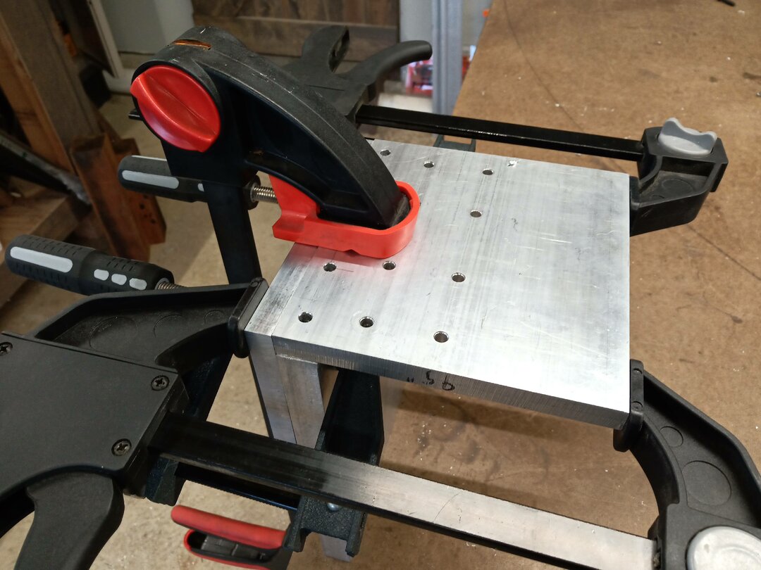
So I ordered a bunch of aluminum plates and cut them to size, drilled and tapped all the holes. The following are just a few pics of me hand building the plates. Unfortunately I was not always great at taking pics.
Here you can see the Z axis mounted.
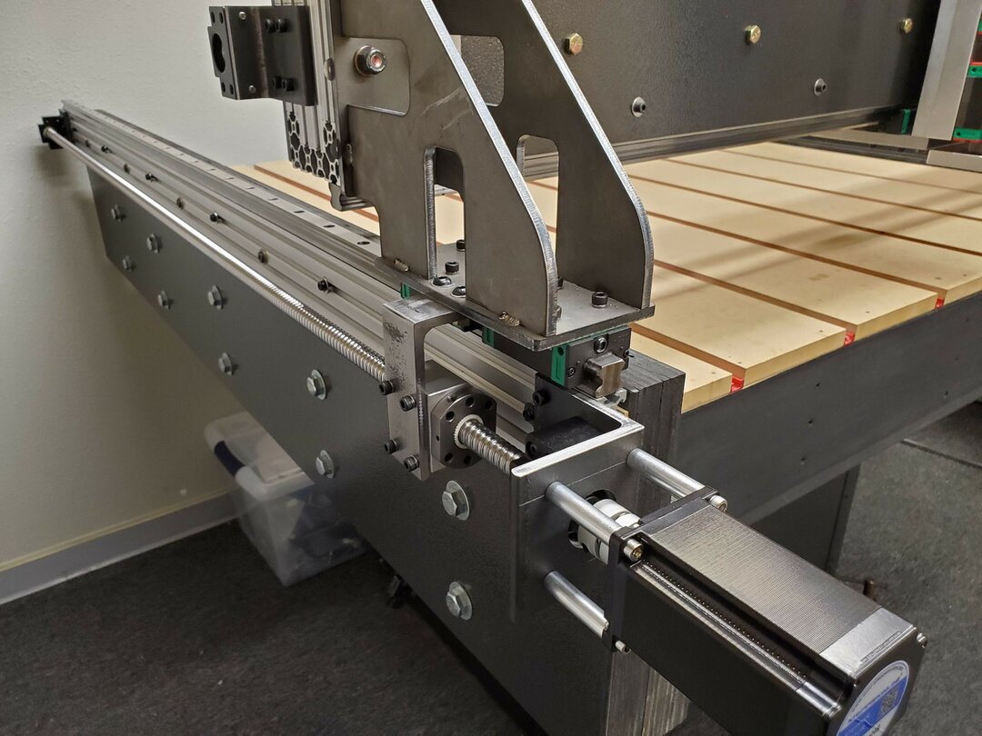
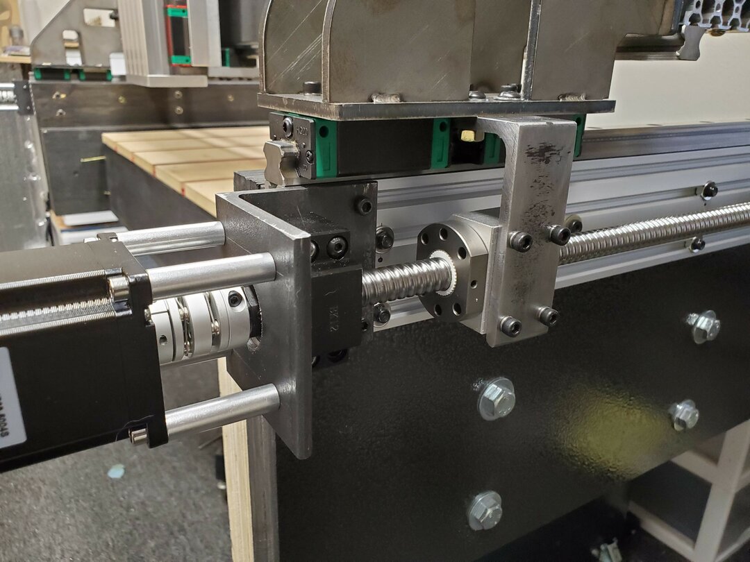
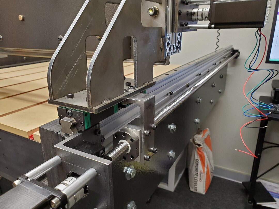
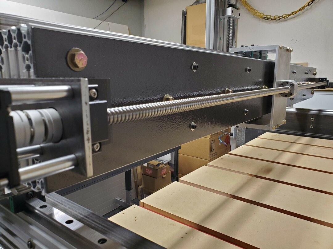
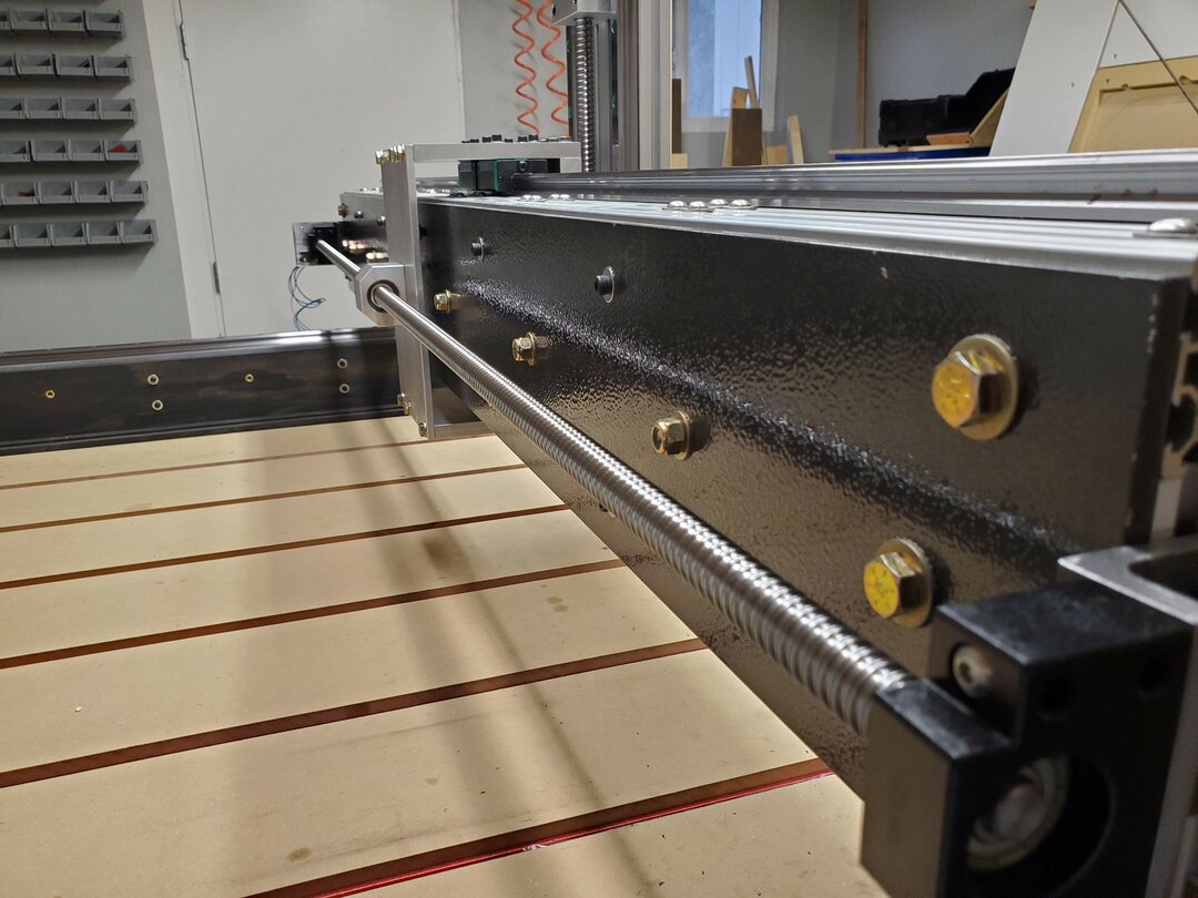
Now that all the axis' are working smoothly it is time to install the ball screws. This was a huge undertaking as I had to figure the logistics out and then design/create all the brackets and mounts by hand. I am not going to document each and every bracket/mount. The following pics just show the final product.
I am currently trying to figure out how to connect all the electronics. I never thought that it would be so complicated.
The following are the electrical components I have purchased and need to hook up.
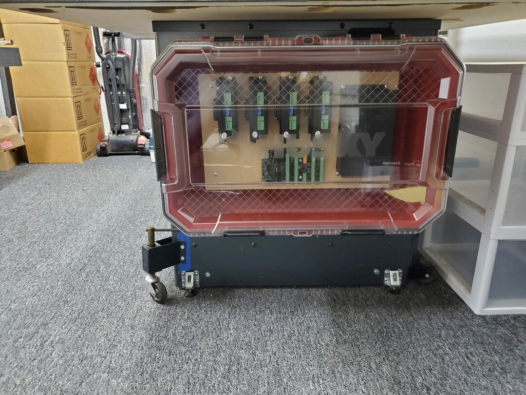
Here is my first attempt at building a control panel. I have since learned that I cannot use the MDF mounting board and need to use either aluminum or steel. I have an aluminum plate on the way. The enclosure fits perfectly and is out of the way, yet easy to view and access if needed.
- Mesa - 7I76E STEP/IO Step & dir plus I/O daughtercard
- SMPS 60V1200W switching power supply 60V20A DC power transformer AC220V / 110V to DC60V1500W Electric machine power supply
- MEAN WELL MDR-60-24 DIN-Rail Power Supply 24V 2.5 Amp 60W
- DM860T Digital Stepper Motor Driver 2.4-7.2A 18-80VAC or 36-110VDC Stepper Motor Controller for CNC
- STEPPERONLINE High Torque Nema 23 CNC Stepper Motor 114mm 425oz.in/3Nm (Z axis)
- STEPPERONLINE Nema 24 Stepper Motor 3.5Nm 5A 4-lead 60x60x98mm Stepping Motor 10mm Shaft for CNC (X/Y axis)
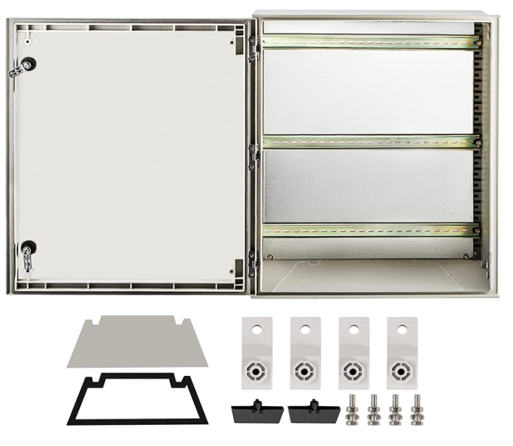
Update: I cancelled my order for the aluminum plate and decided to just purchase a 20"x24"x9" electrical cabinet.
Also I have decided to draw up an electrical panel diagram so I can see what I need and where it goes so that it all makes sense in my head before installing things willy-nilly.
I know there may be a lot of mistakes in my design but that is to be expected. I am planning to upgrade and fix things as I go.
Custom 4x4 CNC
Build in 'Cartesian Style CNC' published by Sray69, Nov 5, 2022.
I started designing and ordering parts for this build back in Oct 2021. Unfortunately life got in the way and I had to sideline the project to deal with more important projects. I am now back working on this project full time. I originally was building a MPCNC on this torsion box platform I built but quickly realized how difficult it would be to produce anything with good accuracy. So I decided to design my own CNC that would be more robust and accurate.
-
-
Build Author Sray69, Find all builds by Sray69
-
- Loading...
-
Build Details
- Build License:
-
- CC - Attribution NonCommercial - No Derivs - CC BY NC ND
Reason for this Build
I wanted a CNC that was robust and large enough to do some decent size and quality projects but did not want to spend a ton of money. I realized that if I built my own I could have much better quality components for a lot less. -
Parts list
Qty Part Name Part Link Comments 1 Mesa - 7I76E http://store.mesanet.com/index.php?route=product/product&... Link 1 SMPS 60V1200W switching power supply https://www.alibaba.com/product-detail/SMPS-60V1200W-swit... Link 1 Mean Well PS 24V 2.5 Amp 60W https://smile.amazon.com/gp/product/B005T6OBFU/ref=crt_ew... Link 1 DM860T Digital Stepper Motor Driver https://www.aliexpress.com/snapshot/0.html?spm=a2g0s.9042... Link 1 High Torque Nema 23 CNC Stepper Motor 114mm 425oz https://smile.amazon.com/dp/B00PNEPW4C?psc=1&ref=... Link 1 Nema 24 Stepper Motor 3.5Nm 5A 495oz https://www.aliexpress.us/item/2255800247134399.html?spm=... Link 1 Z axis HGR20 linear rail /SFU1605/1610 Ball screw https://www.aliexpress.com/item/4000015366449.html?spm=a2... Link 2 2x 1500mm Linear Rail + 1x 1550mm Ball Screw https://smile.amazon.com/dp/B08TR4DZNM?pf_rd_p=f432e763-8... Link 1 1x 1550mm Ball Screw https://smile.amazon.com/Creabygirls-BallScrew-1605-1550m... Link Needed an extra ball screw