Crypt-CubeUpdate 2-19-21
Peek Material Testing:
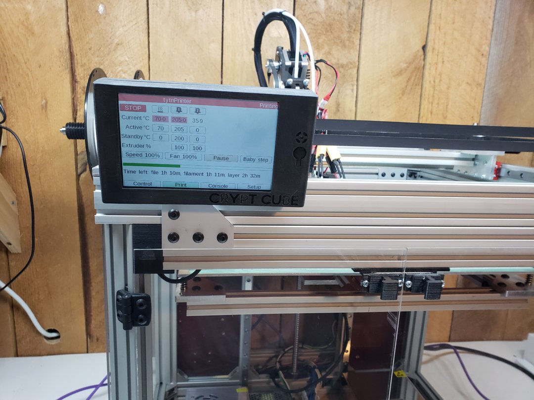
Nozzle Temp: 350c
Bed Temp: 140c
Everything was stable and the print completed successfully. Peek is something I will not print often but at least I know it can been done on this printer. Another step forward in having an all around printer in one application.
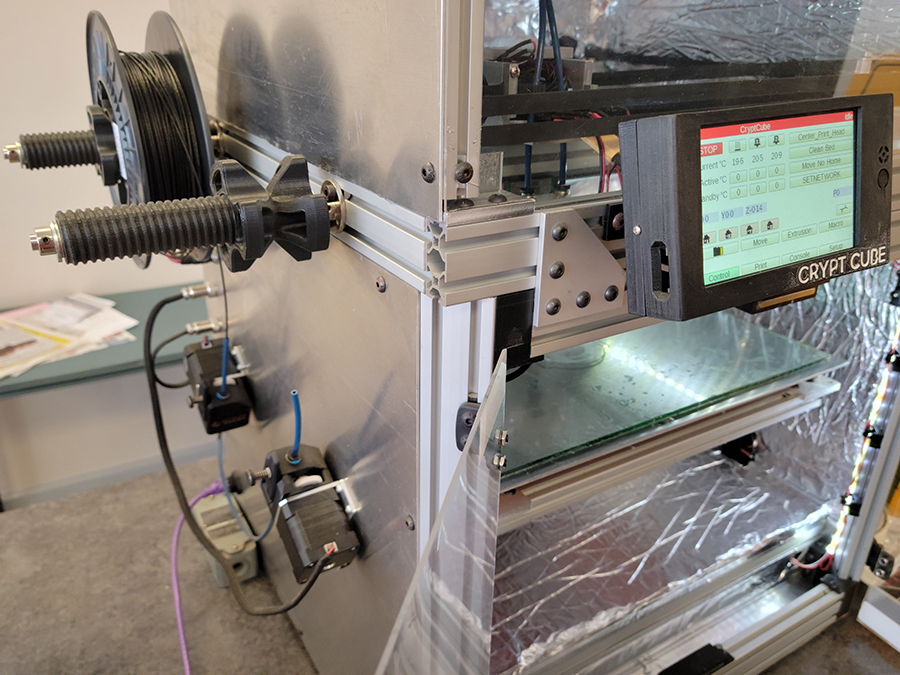
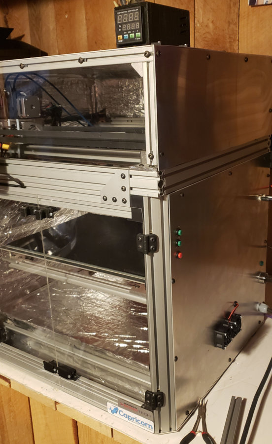
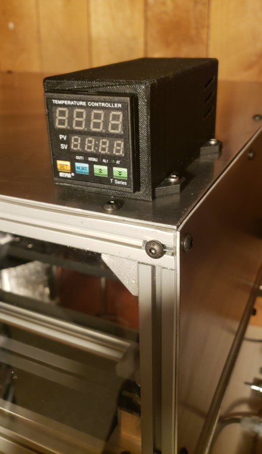
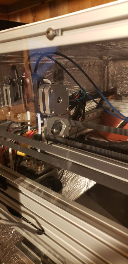
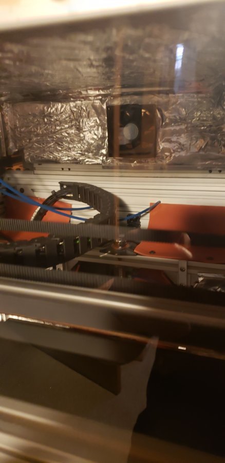
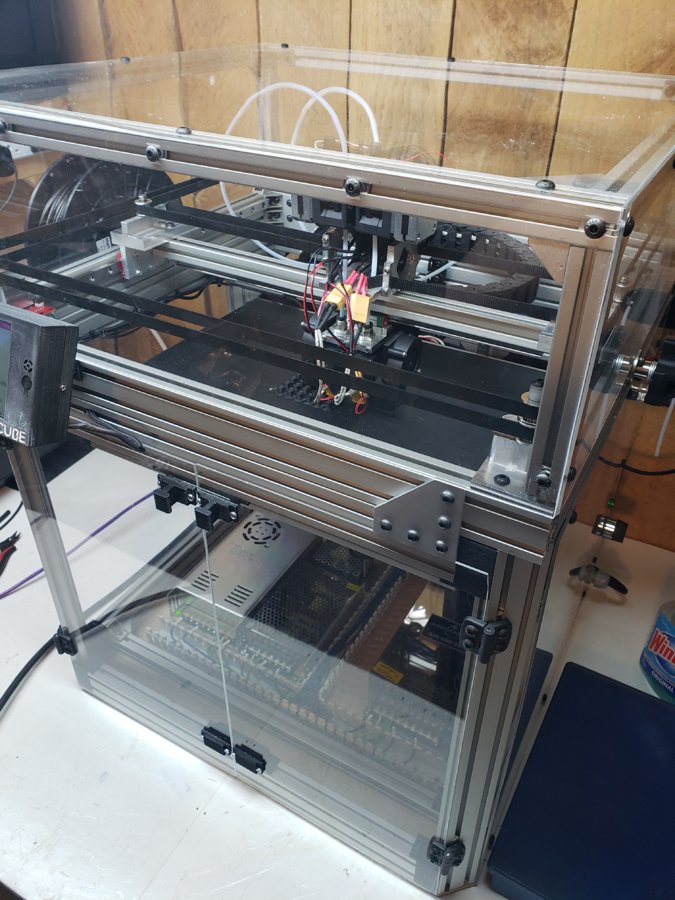
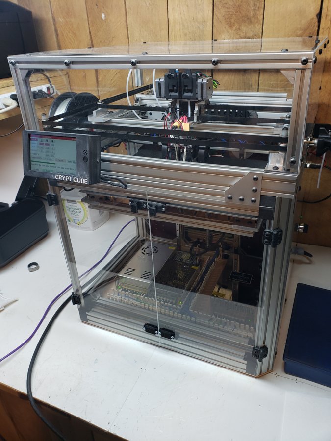
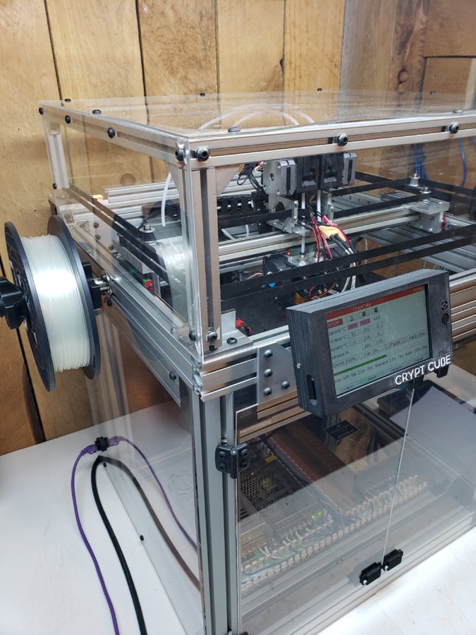
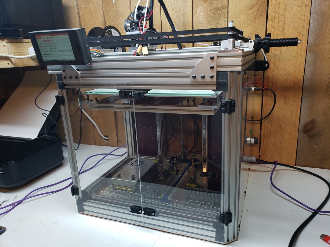
Update 2-18-21
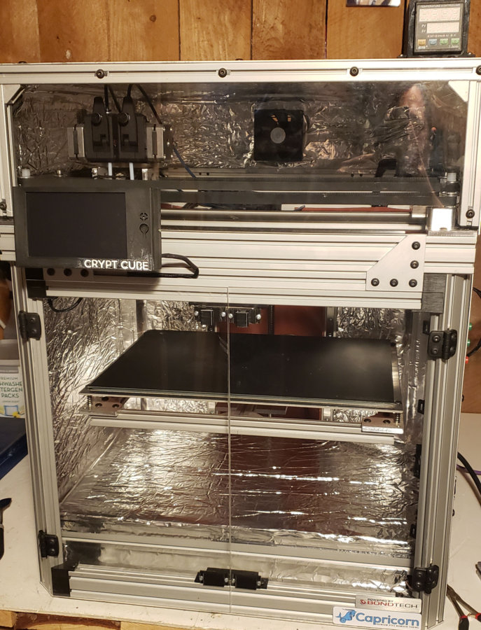
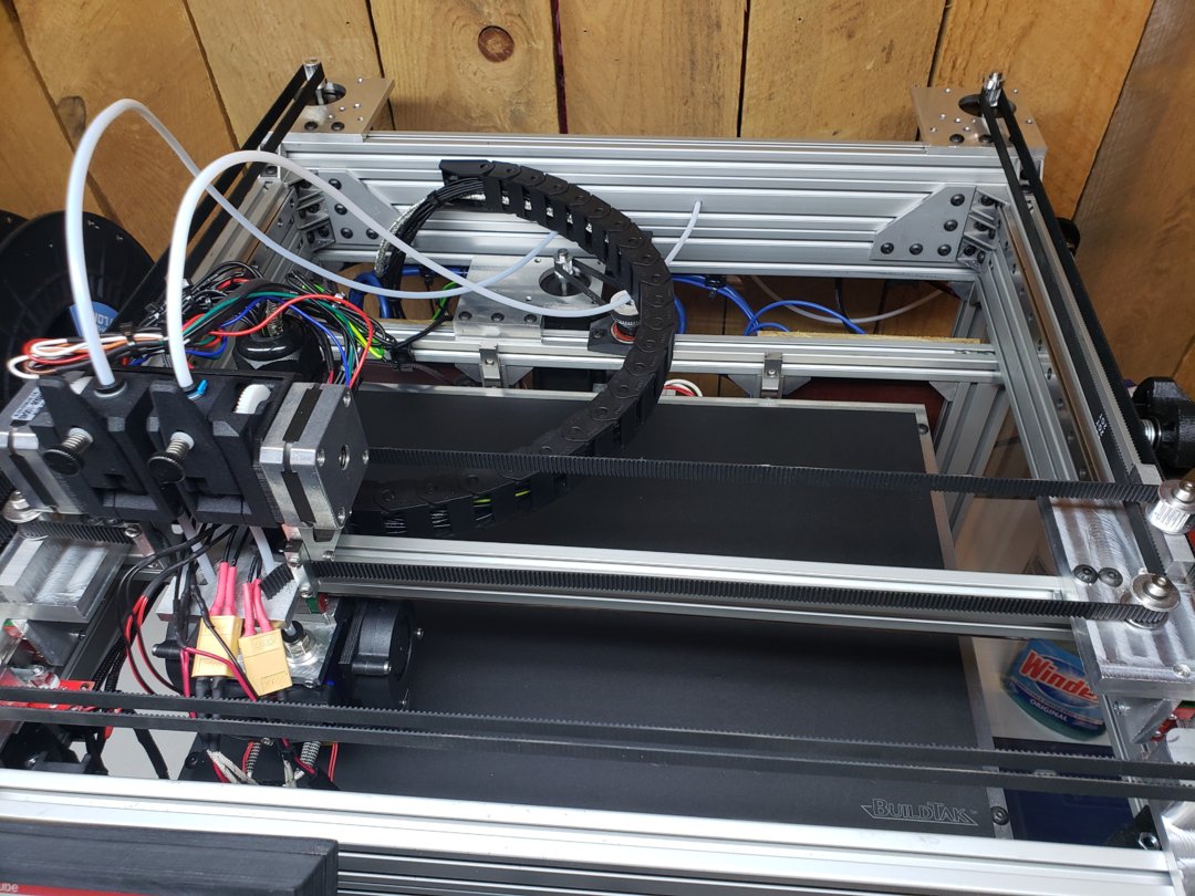
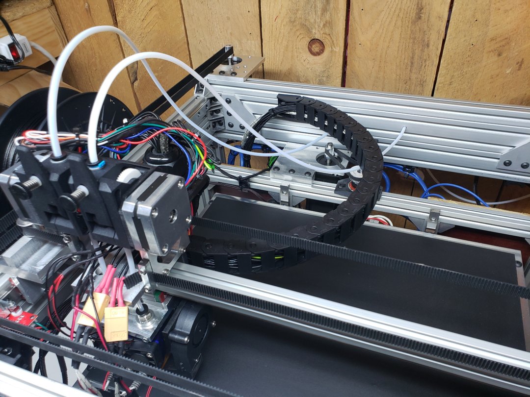
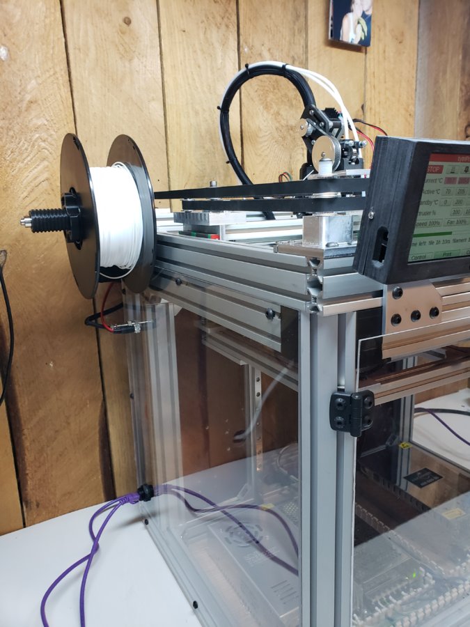
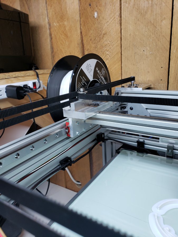
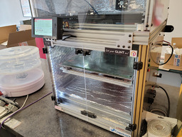
Newest images of build.
Update 6-25-19
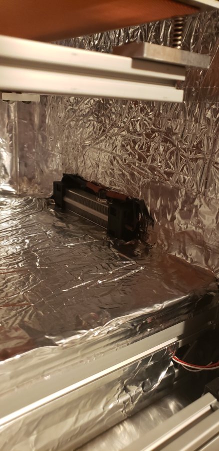
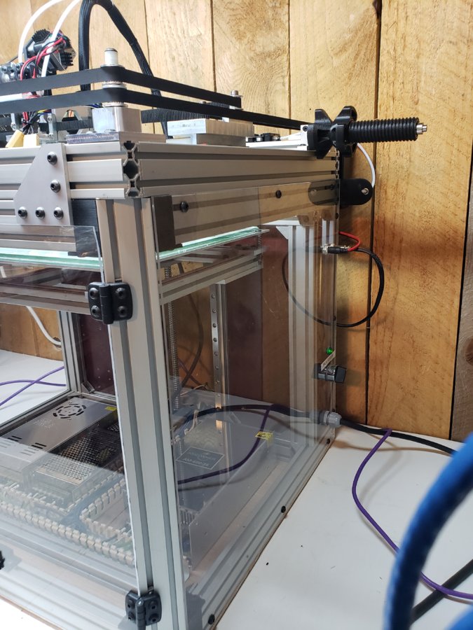
So i did a major rework on some of the issues I was noticing on this printer. For one the plexiglass was deforming from the internal temp, so I removed almost all of it and put 14ga aluminum plating around the exterior of the printer. I also added insulation on all walls of the printer and made a heat barrier out of silicon padding to shield the electronic components from the internal heat. Prior to doing so the MCU on the Duet board would reach 65-70C while long prints were running with a bed temp of 110C. Now the MCU never rises above 36C. I also aluminum plated the power supplies off from the build chamber and put their own intake and outtake fans to remove heat from that compartment. On top of the printer is a temperature control unit to maintain the enclosure heat, this is also controlling a 250w heater I installed inside the chamber. There are also LED strip lights installed so you can see inside easier although I forgot to take pictures with them on.
Update 6-13-19
After many prints I have noticed things that need improved. The main area is the enclosure itself! Printing material which require a high bed temp for adhesion and heat within the chamber cause the plexiglass to warp, allowing the heated chamber to break seal in many areas cooling the chamber. To combat this I have decided to swap out all the plexiglass on the sides and top with 14 and 16 gauge aluminum panels. The front of the printer will remain plexiglass to maintain visual access to the ongoing print but may require switching to a more heat resistant material (glass) at a later date.
I am also switching the PTFE to the Capricorn Bowden PTFE Tubing which has a lower friction rating and more heat resistance.
I will post pictures soon on the updates.
Update 4-23-19
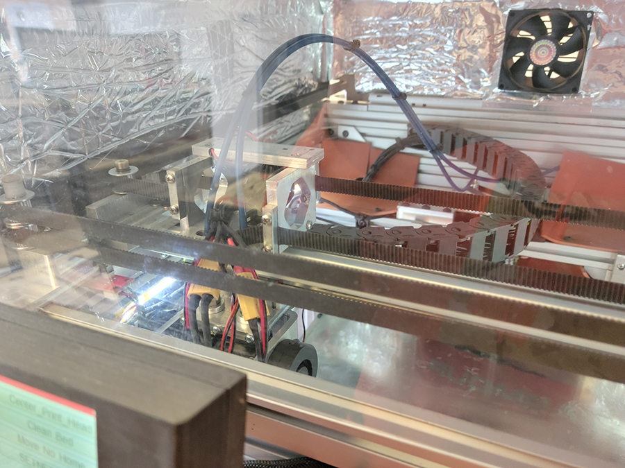
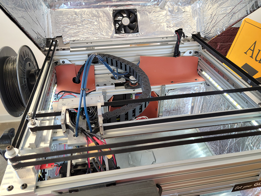
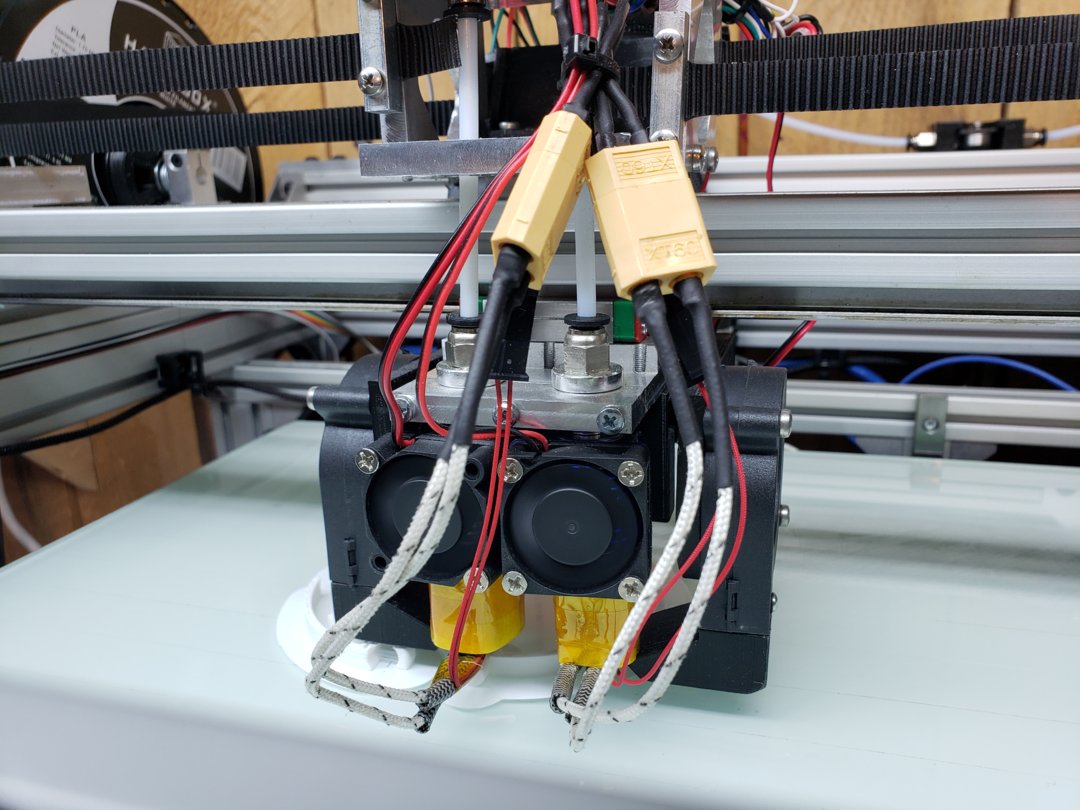
I've finished rewiring, making the top enclosure and changing the wiring to the extruder heads. I decided to run the wiring within some energy track (drag chain) for a neater install and to save some height for the upper enclosure.
Update 4-4-19
I decided to totally rewire this printer and finish the top of the enclosure. Every time I looked at the printer I was unhappy with my initial wiring job. Now the main wiring harness is ran through a cable drag chain to the print carriage and things just look cleaner. I will be posting updated pictures soon.
Update 3-22-19:
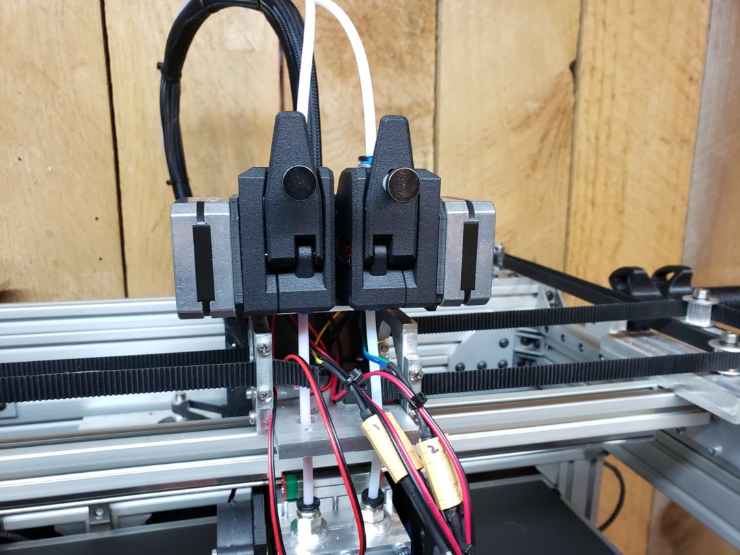
I have changed the extruders, changed the heat blocks, and nozzles.
Extruders: Bondtech BMG
Heat blocks: E3D Copper Plated Volcano
Nozzles: E3D Nozzle X (Olsson Ruby's on hold)
The most frustrating part of building 3D printers is the amount of time to dial everything in and determine mechanical issues verse settings.
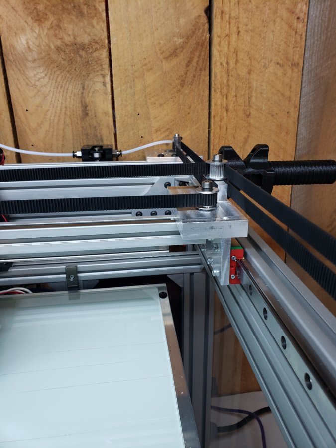
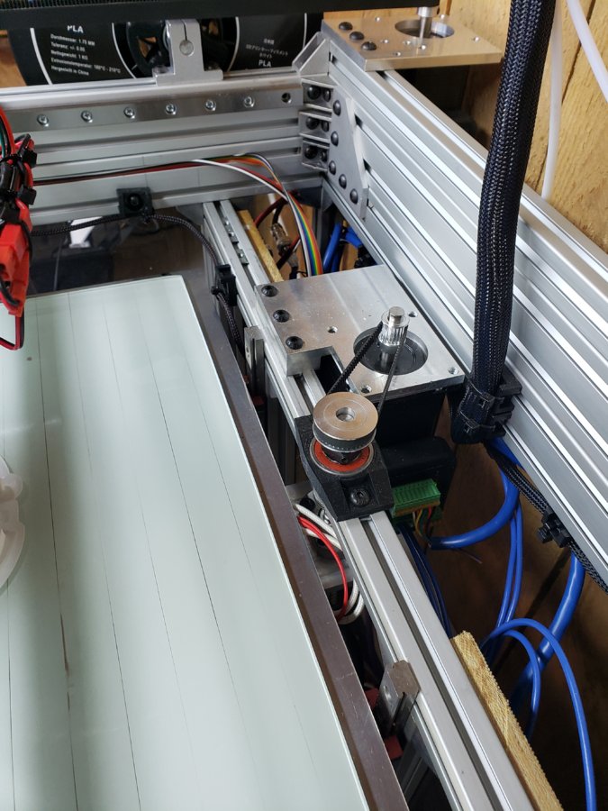
I am using 3 hybrid stepper motors with a built in drive and encoder running 128 micro stepping. All mounts are milled aluminum, all but 2 pulleys are mounted using precision shoulder bolts to eliminate the smallest play. The z-axis is driven with a 12mm ball screw with a 5mm lead.
As of right now one extruder is bowden style while the other is a custom direct drive. I am planing on using the bowden extruder strictly for support material and utilizing the direct drive for all other filaments.
The bed is powered by 120v heater while the extruders are using 50w 24v systems.
Both extruders are E3D Volcano Extruders with Olsson Ruby tips (0.4mm and 0.8mm).
Though this build is more than half enclosed I am working on designing the back and top cover. (every time I come up with something I change and re-change the design)
Soon I plan on making the top cover and back access doors to complete this fully enclosed printer.
I have also noticed that I may have to use another printer and reprint my direct drive extruder in nylon as the heat from the stepper motor us warping the motor mount (not badly but enough I wouldn't trust a long print to not fail with the filament stopping).
As I said it is still a work in progress but getting close to completion.
I will add photos of the wiring compartment soon. I am currently in the middle of test printing.
The doors on this build are magnetic so they stay shut during printing and while not in use. The handles and hardware for the door was 3d printed on another printer.
X-Y-Z
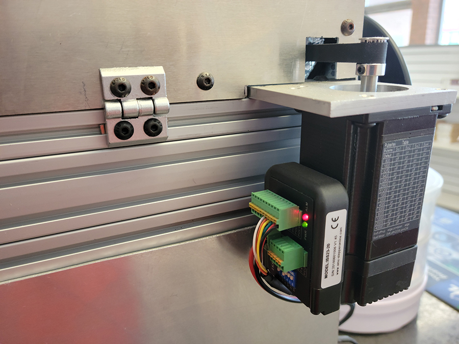
Integrated Stepper Servo Motor 2Nm (283 oz-in)

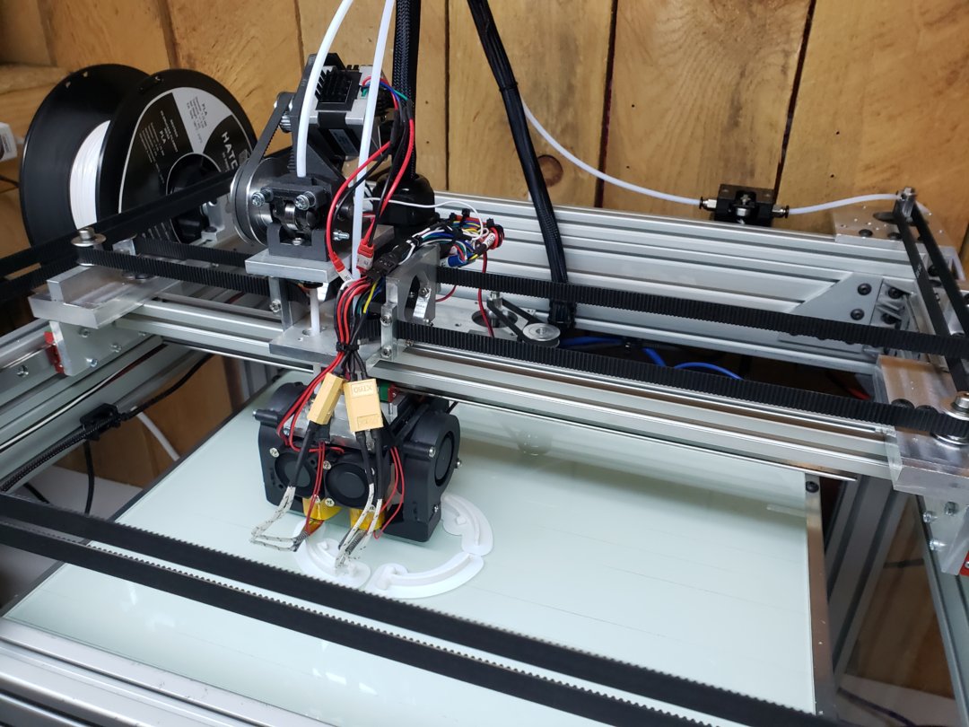
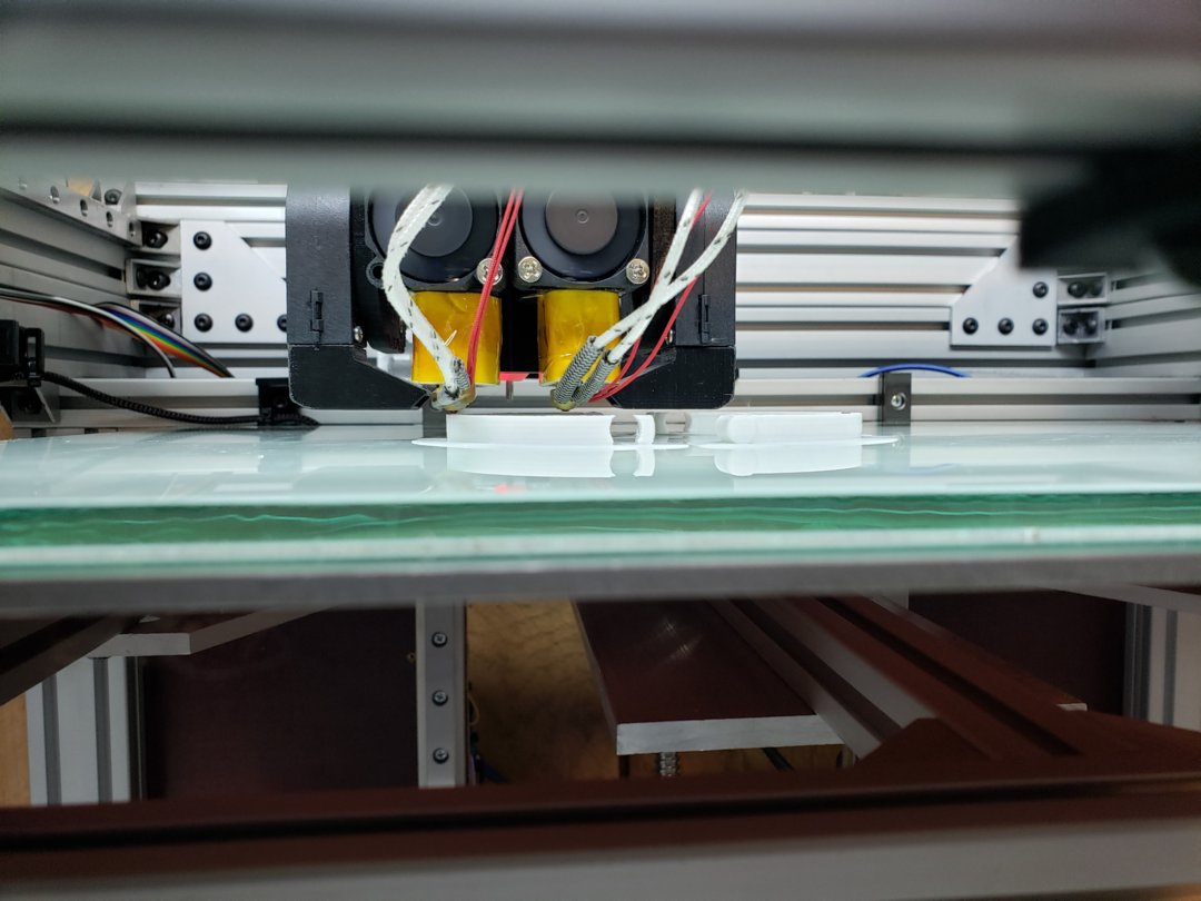
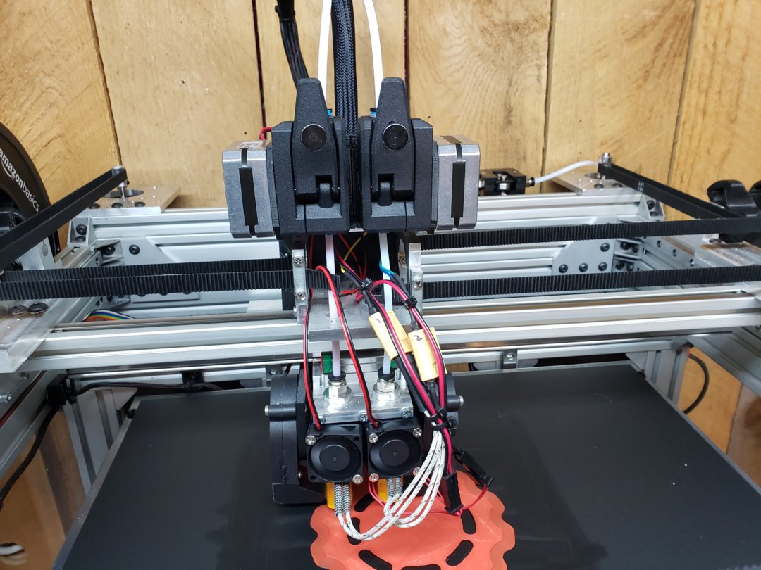
I decided to change my custom extruder with 2 direct drive Bondtech BMG's. I still am debating on the Volcano Nozzles, I am not completely sold. I like to print 0.4mm but I am having issues with the Volcano over heating filament and I believe I am experiencing slight clogging (noticed with the audible click) every once and a while in the BMG.
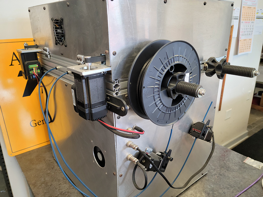
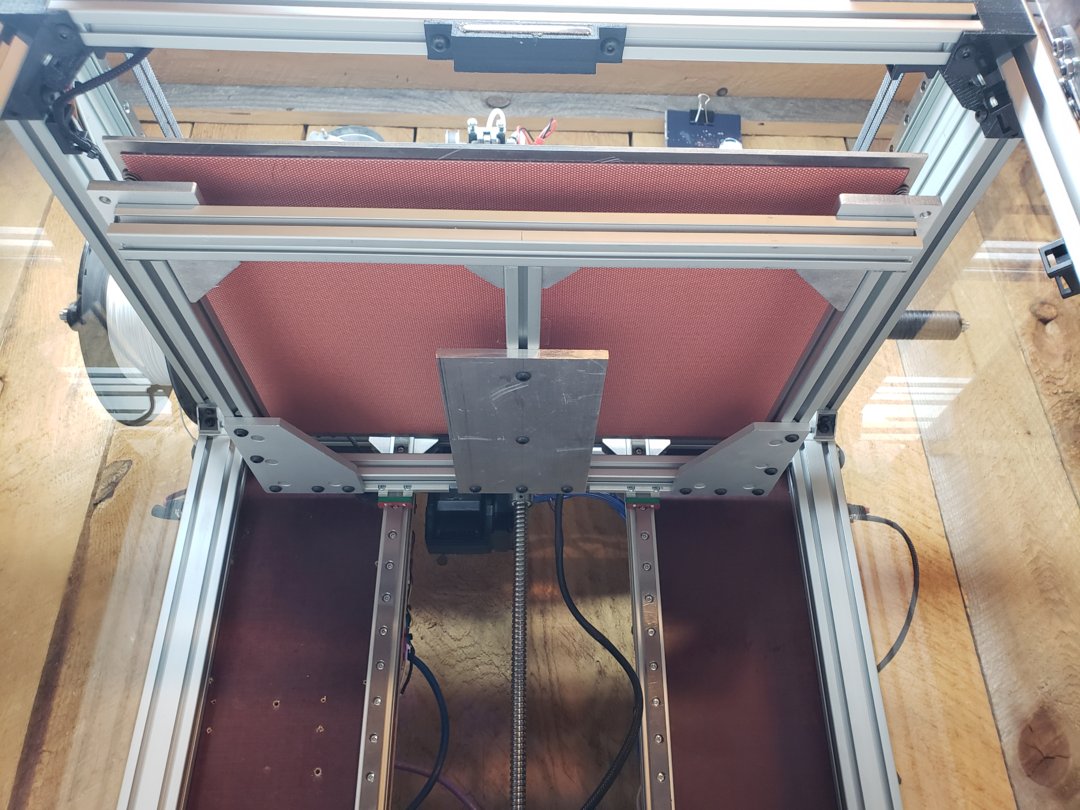
Below is the Z axis drive connected to a 12mm diameter ball screw with a 5mm pitch.
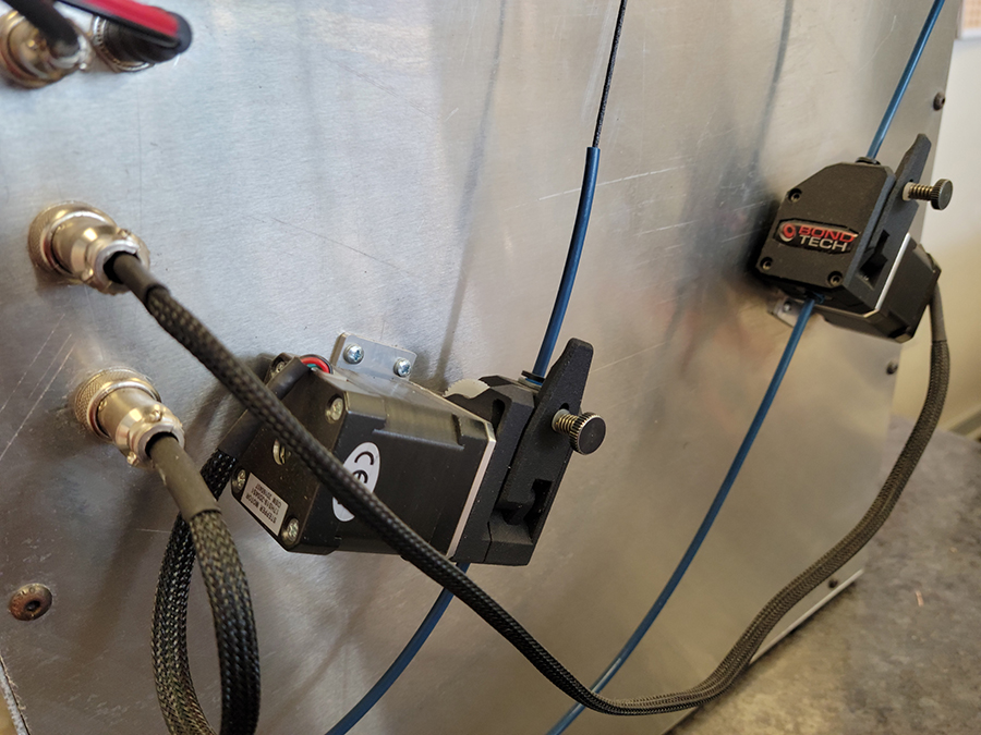
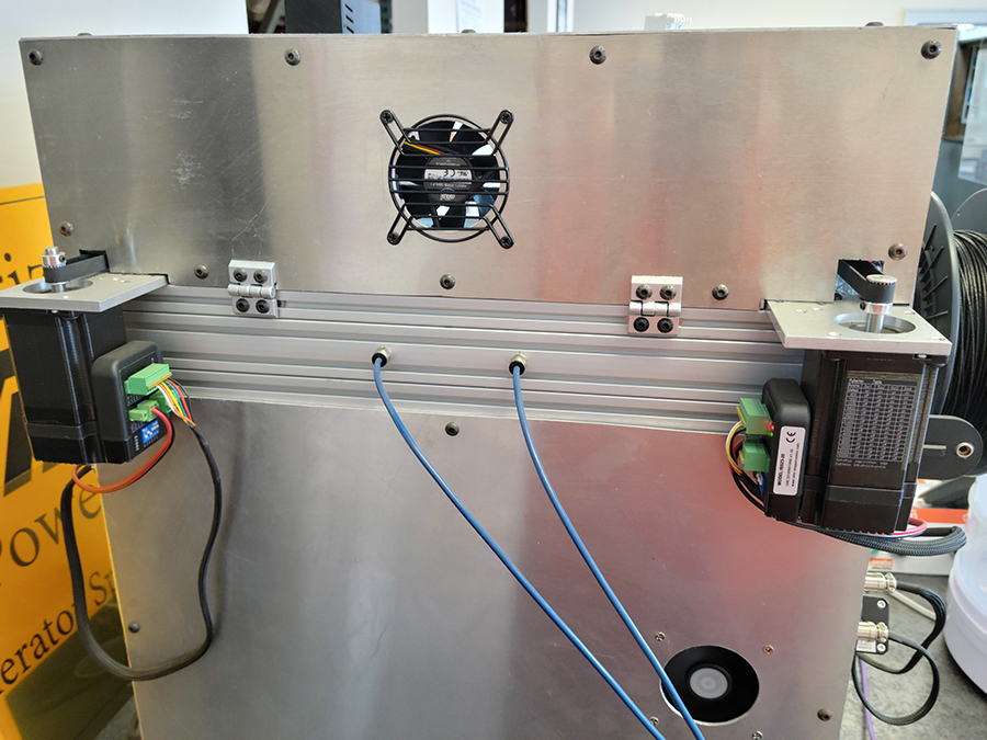
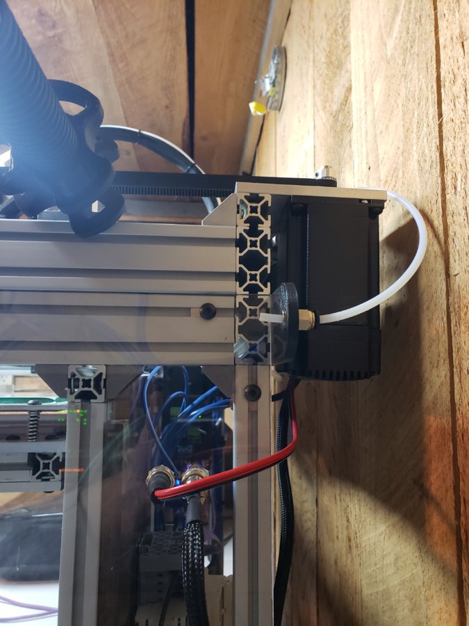
The X and Y drive motors are mounted on the outside of the frame with the wires passing through quick change connectors. I wanted to be able to disconnect and change them if ever needed without opening the case and rewiring back to the duet motherboard.
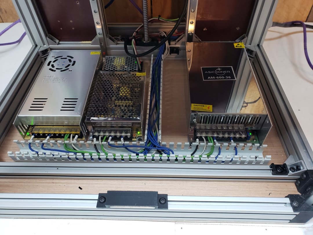
Wiring neatly tucked in the Panduit (I should have put the covers on for the photos). The power supplies are a 24v(extruders), 36v(hybrids servos), 5v(duet controller), and a 12v(lighting and some other features not yet installed). The headbed is 110v directly connected with a solid state relay to the controller.
Though the print below failed the first layers where outstanding! The print failed due to ABS popping off mid print, this was my fault as I forgot to adjust the heatbed temp for ABS.
crypt-cube
Build in 'H-Bot and Core XY' published by crypt-tek, Feb 19, 2021.
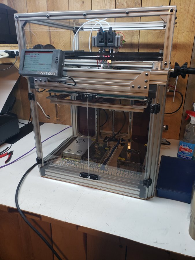
The crypt-cube is another project I've been working on off and on over the past year, unlike my previous built C3DO this is a much smaller built with a volume of 318mm x 240mm x 220mm. With this build my main focus is precision and speed.
-
-
Build Author crypt-tek, Find all builds by crypt-tek
-
- Loading...
-
Build Details
- Build License:
-
- CC - Creative Commons Public Domain (CCO 1+)
Reason for this Build
Seemed like a good idea.


