Removal of the previous control board:
Bottom screw:

USB and 18v input board:

Two screws on each side hold the flat silver brace in place:


Once the metal brace was flexed slightly, it was removed along with the voltage regulator. I didn't use the regulator but it could be used to drop the 18v input to 12v for controlling the solenoid.


A few more screws to remove the plastic covering and expose the control board:

There it is:


I labeled all the wires and removed the control board:


Control board replacement:
Experimenting with micro switch positions using poster putty:

Showing the pairs of windings for the stepper motors:


Checking the fit of the ESP32 control board mounting piece:


and the switches along with new paper labels:


MOSFET:

Once I was sure about the rest of the wires (which could be installed non-destructively), I cut off the end of the USB extension so that I could install a microUSB plug (for plugging into the ESP32 board).


With the board in place, it was time to put everything else back together:


Putting it all back together:


Software & Configuration
With the hardware ready to go, it was time to switch to the software and configuration. To get everything started, I set up the ESP32 GRBL development board per the instructions below using the recommended ESP32 board, stepper drivers, and SD card module.
Grbl_ESP32 Development Board Instructions at Buildlog.Net Blog
I followed the instructions below to set up the bluetooth component. I didn't have much luck until I happened to name the device the same as the developer (ESP32BT) and restarted the bluetooth radio on my phone (which is probably what actually fixed it but that would be the first thing I'd look at if I had issues and had named it something else).
Grbl_ESP32 with Bluetooth Serial Support at Buildlog.Net Blog
There was helpful information at Cricut Repair Info « everhack especially:
Cutter head voice coil voltages:
"At all pressure settings, when idling, I measured 3.6v, with the positive lead on the blue wire, and negative lead on the red wire. When measured against ground, the blue lead reads 4.44v, and the red lead 0.76v. While cutting on “min” pressure, I read -1.67v (blue 0.69v, red 2.39v).
At “low” pressure, -2.84v (blue 0.73v, red 3.6v)
At “med” pressure, -5.36v (blue 0.77v, red 6.13v)
At “high” pressure, -8.44v (blue 0.82v, red 9.26v)
At “max” pressure, -11.75v (blue 0.86v, red 12.72v)"
Since I had already hooked up everything with 18v, I set the maximum "spindle speed" to 18 (i.e. 18v) but always run stuff at a "speed" of 8 or 9 which uses PWM to lower the effective voltage the solenoid (or voice coil in this case) sees.
There was also helpful information at Cricut | Built to Spec, especially:
The stepper model 42BYGH4418 and other miscellaneous information (would have been more helpful with other models from Cricut). Specs for the stepper model above were found at this link:
New Model Old Model No.of Phase Voltage Current Inductance Resistance Holding Rotor Weight Length Lead Torque Inertia Wire Number: 42BHH44-038B 42BYGH4418B-08 4 12 0.38 32 30 3.2 60 0.33 44 6
(take away was 0.38a max current which was used earlier for setting the stepper drivers).
If I had needed to feed 12v to the voice coil then I was going to use the LM317 voltage regulator that came with the Cricut. Resistor values to use are at:
LM317 Voltage Calculator | REUK.co.uk
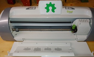
The 3d printed parts used:
Open Hardware logo to cover LCD hole:
Cricut Expressions 2 Display Hole Cover by mredmon
Mounting board:
Cricut Expressions 2 Mount For ESP32 Control Board by mredmon
I originally planned on just using a RFP30N06 MOSFET control board I ordered off of Amazon that claimed it worked with 3v signals but it didn't. So I added a TIP120 transistor to trigger it with 5v.
Helpful sites for gcode explanations:
G-Code - ShapeOko
M Codes
GRBL settings/explanations:
bdring/Grbl_Esp32
ESP GRBL site:
bdring/Grbl_Esp32
GRBL Controller for Android:
zeevy/grblcontroller
At first, I was getting wobbly/rounded lines that didn't quite line up.

Turned out the belt for the y-axis was too loose. There was no adjustment so I ordered a new belt off eBay. Until the belt arrived, I temporarily tightened the existing belt:

With the new belt, things were better but not quite perfect.

I needed a gcode generator that took into account the small swiveling blade of the vinyl cutter (instead of treating it like a laser). I'm working on the exact workflow but, in the meantime, it works great as a plotter (poster is 11 inches wide and plotted with metallic Sharpies):

Cricut Expressions 2 to ESP32 GRBL Control
Build in 'Everything Else' published by MattR, Nov 18, 2018.
A log of my "brain surgery" on a Cricut Expressions 2 to change the control board to something open so that I could cut what I wanted. The ESP32 GRBL board I used has bluetooth and WIFI built-in and was very easy to get working just the way I wanted.
-
-
Build Author MattR, Find all builds by MattR
-
- Loading...
-
Build Details
- Build License:
-
- CC - Attribution - CC BY
-
Parts list
Qty Part Name Part Link Comments 1 GRBL ESP32 Development Board https://www.tindie.com/products/33366583/grblesp32-cnc-de... Link $35 1 5-Pin Micro USB Type B Male Connector https://www.amazon.com/gp/product/B014GMP4E4/ Link $0.60 (1 of 10 used) 1 RFP30N06LE TO-220 Mosfet Power Control Board https://www.amazon.com/gp/product/B00V9XF1RY/ Link $2.80 (1 of 5 used but also had to use a TIP120 transistor I had in my parts bin and I added a 1N4004 "snubber diode") 1 HiLetgo ESP-WROOM-32 ESP32 ESP-32S Development Boa https://www.amazon.com/gp/product/B0718T232Z/ Link $11 2 DRV8825 4-Layer StepStick Stepper Motor Drivers https://www.amazon.com/gp/product/B01FF9YX4Y/ Link $2.80 (2 of 5 used) 1 Micro SD Card Module https://www.amazon.com/gp/product/B01JYNEX56/ Link $1.70 (1 of 5 used) 1 Miscellaneous Parts Link 1x 1N4004 diode, 1x TIP120 transistor, 4 surface mount tactile buttons, wire 1 Crimper and Dupont Connector Kit https://www.amazon.com/gp/product/B017JU20Z6/ Link I already had this crimper along with a Hilitchi 635pc kit. It takes practice to use but works. 0 Link
