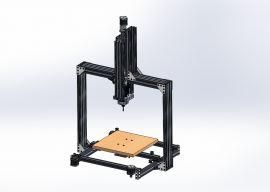
Key characteristics
Build volume:

X-Y Axis: CoreXY 9mm GT2 belt system, two plane configuration
- X: 293mm (11.53")
- Y: 290.75mm (11.44")
- Z: 223.83mm (8.81")
Z Axis: 250mm Lead screw in unique symmetric mounting configuration
Design Rationale
The main reason for this build is I want to try out a few ideas I had and see how well they worked. Starting with the X-Y table:

I've always liked the CoreXY configuration but I don't really like the crossing belts, so I built it in two planes. Plane 1 (Top plane):

Plane 2 (Bottom plane):

Except the belts aren't continuous through the gantry like shown in the model, they terminate at connection points on either side of each plate:

I like this configuration because it means the gantry plates are being pulled from both the top and bottom connections at the same time and because those connection points are axisymmetric there are no torques in the system at all (like you would get if you pulled just from the top). I also increased the belt width to 9mm since I noticed that the pulleys can handle that width.
Probably the most unique feature of this build is the Z axis, here it is at the top:

And fully lowered:

I just haven't see a build with a Z axis that was symmetric about the gantry before and the idea appealed to me. I really just want to see how well it works. Couple more pictures:


That's an anti-backlash nut in the center. Yeah it's a lot of brackets, but this setup really maximizes the use of the lead screw since you don't have a big plate eating up a lot of the travel, or anything obstructing in your build volume. Basically I wanted the most amount of Z axis build volume I could get, and the conventional setup would mean a long actuator bolted-on to the side of a tall gantry, which seemed way too flimsy to me. This setup means there's a central axis going through the stepper, the lead screw, the gantry's center point, and the router.
Currently all parts have been ordered and shipped, and when I get those next week I'll start building.
CoreXY Tower
Build in 'X/Y Table Style CNC Mill' published by Eric Foster, Jul 30, 2015.
CoreXY Table with Symmetric Lead Screw Z axis, Build volume: 293mm x 290.75mm x 223.83mm
-
-
-
- Build Progress:
-
- Build in Progress...
Jo0, Barry Ward, DuncanF and 2 others like this. -
-
Build Author Eric Foster, Find all builds by Eric Foster
-
- Loading...
-
Build Details
- Build License:
-
- CC - Attribution Share Alike - CC BY SA

