
I plan on building this mid December. Our own builder, Carl Feniak, convinced me to take a second look at this design with a bowden extruder concept. My main objection to a bowden was it's problems printing flex filament. I've discovered the E3D v6 is designed to do that, so I have incorporated it into the design. The first image is altered to show the E3D v6 and Carl's bowden drive mechanism and the SKP in Files has changed. I'v also moved the PSU and controller box below the build area to give the user more room for replacing the spool and threading the bowden driver. I have also changed the livense to Attribution NonCommercial - Share Alike.
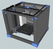
The core idea was to create a compact corexy design where all parts, including the spool, power supply, and controller are located within the perimeter of the frame, allowing panels to be added to the outside of the frame for an enclosed box, and to make assembled shipping and handling easy. For a build area of 8.5" x 8.5" x 8.5" the external dimensions are x-17.5" y-15.5" z-15.5".
The idlers for thee XY belts are flanged F625ZZ bearings (2 per idler) and are stacked 2 idlers on a 5mm bolt which can be mounted directly to V-Slot extrusions with standard slip nuts on the x-carriage and front frame bar. This allows assembly with standard off-the-shelf parts (RobotDigg is a great source for F625ZZ) placing one set of belts above the other. The XY belts attach to the min-v wheel x-carriage via a printed part attached to the min-v wheels using extra long bolts for the mini wheel axis. That attaching applies pull to the center of the two top wheels of the x-carriage.
The Z axis runs on a single dual-shaft motor using belts instead of the customary two motor-acme-screw concept. Using one dual-shaft motor eliminates the side-to-side creep of two motors. The Z axis moves on Solid V Wheels against a 80x20 extrusion upright, raising a 80x20 Z-carriage containing the build plate. Homing the Z axis would require dropping the carriage to level with the frame, then clamping the belts to the carriage. Clamping access holes are drilled into the z-carriage struts and can be viewed from the SKP submitted in the Files Section of the build.
![[IMG]](proxy.php?image=http%3A%2F%2F3dwrx.com%2Fopenbuilds%2Fcorex2%2Flayout-e3d.jpg&hash=6218cffdd08ebbe33e3cd75d445dfc10)
![[IMG]](proxy.php?image=http%3A%2F%2F3dwrx.com%2Fopenbuilds%2Fcorex2%2Flayout-black.jpg&hash=50a75093b591785724776e49b4ab5e33)
CoreXY Enclosed
Build in 'H-Bot and Core XY' published by Keith Davis, Nov 16, 2014.
A compact, enclosed Core XY design, based on off-the-shelf parts.
-
-
Build Author Keith Davis, Find all builds by Keith Davis
-
- Loading...
-
Build Details
- Build License:
-
- CC - Attribution NonCommercial - Share Alike - CC BY NC SA
-
Attached Files:
![[IMG]](proxy.php?image=http%3A%2F%2F3dwrx.com%2Fopenbuilds%2Fcorex2%2Flayout-1-b.jpg&hash=edfc76dd08adf79723ae56c9f4758056)
![[IMG]](proxy.php?image=http%3A%2F%2F3dwrx.com%2Fopenbuilds%2Fcorex2%2Flayout-2.jpg&hash=7d3a399410e226d55b3203494d977f7b)
![[IMG]](proxy.php?image=http%3A%2F%2F3dwrx.com%2Fopenbuilds%2Fcorex2%2Flayout-4.jpg&hash=288d8f9dacf6e2435255800440c06a11)
![[IMG]](proxy.php?image=http%3A%2F%2F3dwrx.com%2Fopenbuilds%2Fcorex2%2Flayout-5.jpg&hash=16bf53374c8e06461a5f4f5321f3b3ec)
![[IMG]](proxy.php?image=http%3A%2F%2F3dwrx.com%2Fopenbuilds%2Fcorex2%2Flayout-6.jpg&hash=10e070adc46d20de5bb6a18959e9791c)