
Some 5 or so years ago I decided to add a CO2 laser to my existing CNC machine - the intention was not to convert the machine to a laser but rather just to add an additional tool. Obviously any work done would have to allow all the original features of the machine to fully function so a great deal of thought had to be put into the design and the layout / positioning of the various additional components required.
Not wishing to scare everybody but before proceeding I must point out that adding any type of laser to any CNC machine creates additional dangers and increases the necessary safety precautions that need to be taken both during the operation of the laser and at any time it is available to be brought into action. With a CO2 laser both the laser beam and the high voltage involved cannot be seen but they will bite the unwary if allowed to do so.
Careful design with suitable safety interlocks, together with a key operated master switch (once the key is removed the laser cannot be brought into action) and safety, eye protection, goggles (OD rated at the laser’s wavelength) are essential elements in any build.
Dependant on how and where the laser is intended to be operated there are also mandatory health & safety regulations which have to be complied with so you may need to check these out with your local authorities.
On the brighter side, after 5 years of operating CO2 lasers (both DC excited, glass tube and RF excited, metal tube, types) I have found them to be a lot safer to use than I had originally envisaged and provided adequate safety precautions are taken have found them to be no more dangerous than the basic CNC machine itself and all it’s associated cutting tools.
As a project, adding a CO2 laser is not for the faint-hearted and it is certainly not cheap to do - like all things there is always more than one way to accomplish the task but for those that may be interested this is what I did and how I went about it. I don’t intend to provide full mechanical constructional details as different machines may require different solutions this is just my build which is intended to show what is involved.
This was my original concept of the additional components required and how they would be interconnected.
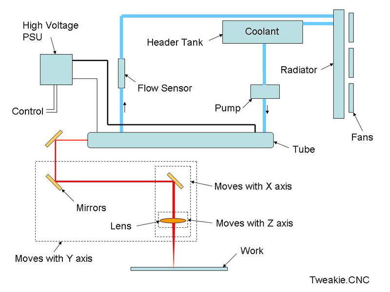
My first task was to find a position on my machine to construct a rigid and stable platform for mounting the glass laser tube (a 40Watt tube is approx. 700mm in length and 50mm in diameter) and fortunately the machine is wide enough to allow additional supports to be fitted with a 15mm thick aluminium plate secured horizontally across the top. This ally plate subsequently formed the base for a box which would totally enclose the tube thus protecting it from damage and also protecting me from any possible IR radiation as well as the high voltage terminal connections.
Actually mounting the tube can be accomplished in various ways but I chose to make these supports, which have to be dimensionally stable as well as allowing for thermal expansion and contraction of the glass envelope, from ally plate then securing the tube in position with two straps made from bungee cord.
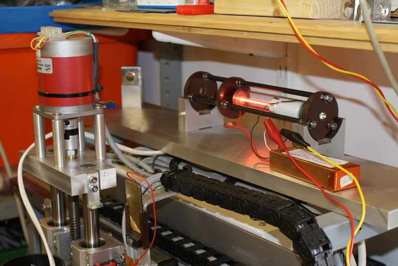
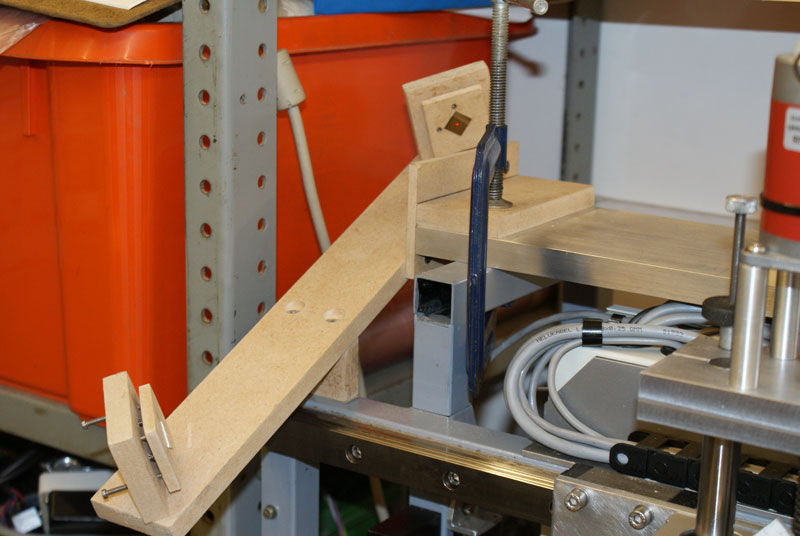
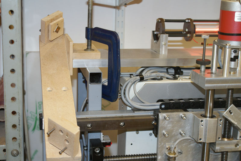
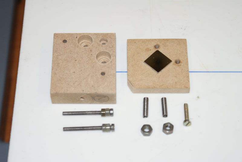
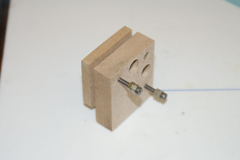
Working out the beam path (getting the laser beam from the tube position to the rotary spindle position) was trial and error. I made some mock-up, adjustable, mirror mounts (using parts cut from a defunct HDD disc for the actual mirrors) and other scraps of MDF and spent a whole day trying various combinations until I found the best option. I suppose I could always have sat down at the computer and designed the beam-path layout in CAD but that would probably have taken me just as long.
To simulate the CO2 laser beam (which is invisible to our eyesight) and to be able to see the actual beam-path I used a small Helium Neon red laser mounted at the same height and position that the CO2 tube would later be fitted. This enabled positioning of the mirrors and provided all the necessary dimensional information to make the final parts from aluminium. The actual mirrors, mountings, and lenses that were going to be used were on order from Newport Corp. and would take a couple of weeks to arrive giving me more than sufficient time to get the cutting and machining work done.
This is the HeNe and the mock-up parts used in establishing the beam-path.
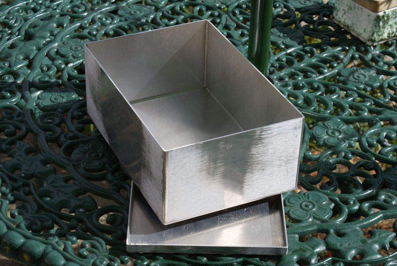
Meanwhile the high voltage PSU had arrived from China and a more suitable (electrically safe) enclosure had to be made so it could be fitted to the side of the machine frame.
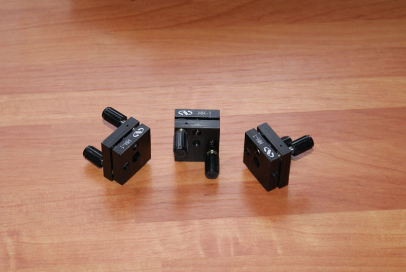
The 3 adjustable mirror mountings duly arrived from Newport Corp. together with 3 mirrors and two lenses. It should perhaps be noted that in terms of finances these parts alone amounted to a greater expenditure than the rest of the build all put together so they deserve to be treated with special care.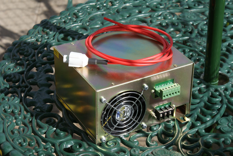
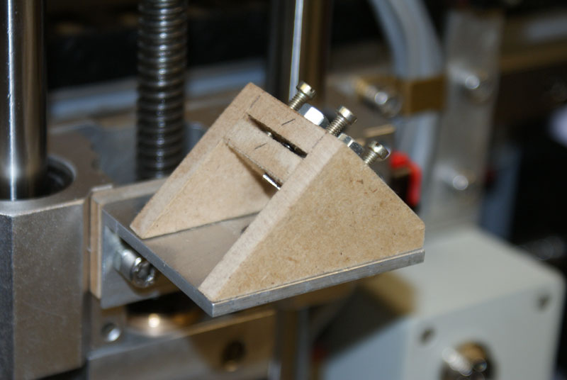
I chose to use an ally box section to enclose mirrors 1 and 2 - this keeps the mirrors clean from debris and protects them from accidental damage or possible misalignment (incidentally, as my machine has a fixed gantry with moving table, mirror 2 remains in a static position and does not travel with the Y axis).
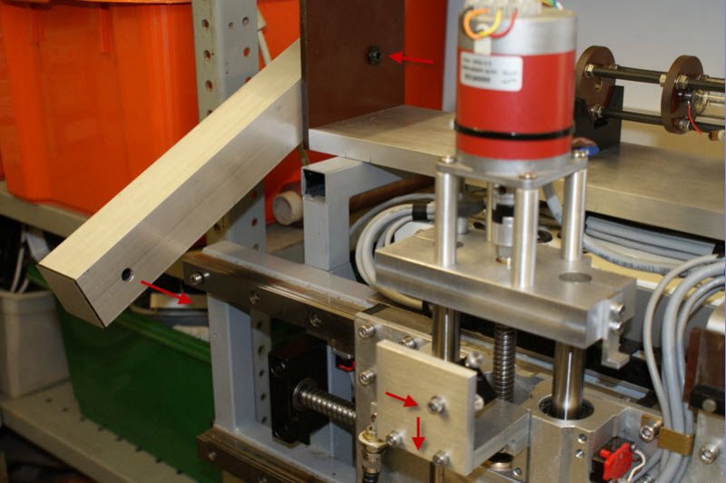
In the second picture here the beam from the laser tube (shown by the arrows) enters the small hole at the top is deflected by mirrors 1 and 2 to emerge from the hole in the box section where it travels to mirror 3 (behind the ally plate) to be deflected downwards to the focus lens and subsequently to the work piece.
To operate at the infrared wavelength of CO2 lasers (10600 nm) the focus lense needs to be made of special materials. This one is Zinc Selenide (ZnSe) it is Plano Convex with a focal distance of 50.8mm and is coated on both sides with an Anti-Reflection (AR) coating. My second lens is similar in design but is made from Gallium Arsenide (GaAs) - each have their own optical merits but perhaps most importantly ZnSe lenses are considerably cheaper than GaAs.
It is a function of physics that a short focal distance lens will produce a smaller focused spot size with a shorter depth of field than a lens with a greater focal distance which in turn has a larger spot size and longer depth of field. This, as a general rule, makes short FD lenses more suitable for engraving and longer FD lenses more suitable for cutting operations. However, from practical experience and the type of work that I do, I am happy to just use a 50.8mm FD lens for cutting and engraving and have found no benefit when changing to longer FD lenses for cutting. So much for the theory.
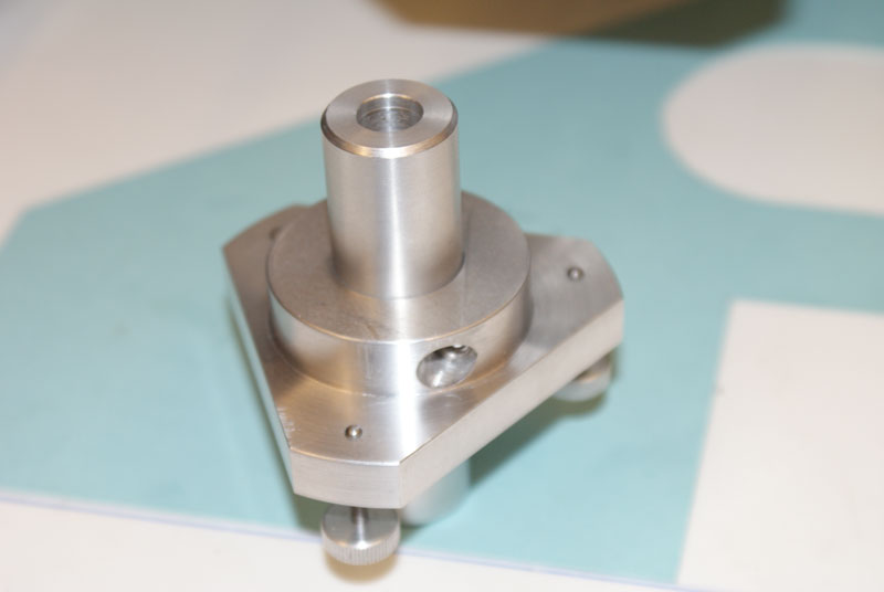
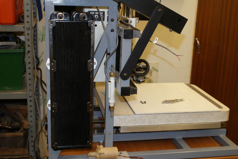
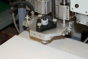
To mount the lens an ally assembly was made to fit exactly into the position that is normally occupied by the spindle motor. In retrospect it was perhaps rather over-engineered but I wanted to make it fully adjustable and time has shown that it works exactly as intended. I can switch between spindle engraving and laser engraving in just a few seconds by removing and swapping between the lens assembly and the spindle motor. No other changes need to be made to the machine.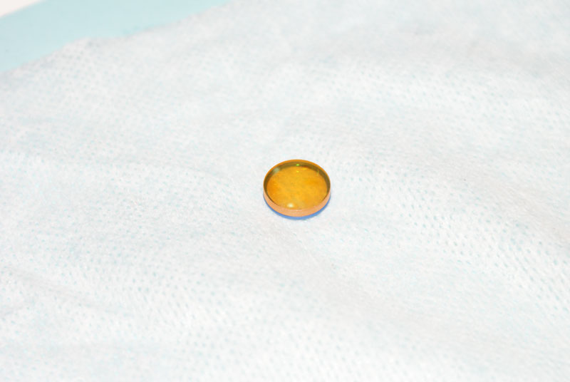
A little bit of rotary engraving to make a label to be fitted to the front cover of the laser PSU enclosure. The striking voltage for the initial plasma arc within the tube is 18,000Volts but this reduces to 16,000Volts once the tube is running and emitting photons. I can’t help thinking that a reduction of 2,000Volts would make little difference if you were on the receiving end so care needs to be taken with the construction of the PSU enclosure and it’s protective ground earthing as well as the HT cable positioning / routing.


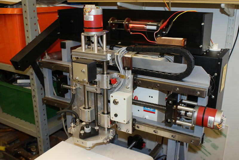
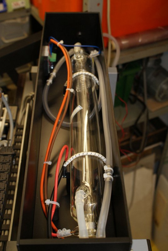
With the optical beam path tried and tested it was now time to start finishing (spraying / anodizing) the various parts and fitting them in position on the machine. The enclosure for the laser tube is taking shape but it was later extended in length to accommodate a longer laser tube.
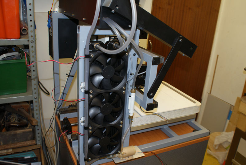
The little HeNe laser was finally removed and the CO2 tube secured onto it’s supports. The cooling radiator, water circulating pump and flow switch have all been fitted to one side of the machine frame - now the plumbing and electrical wiring begins.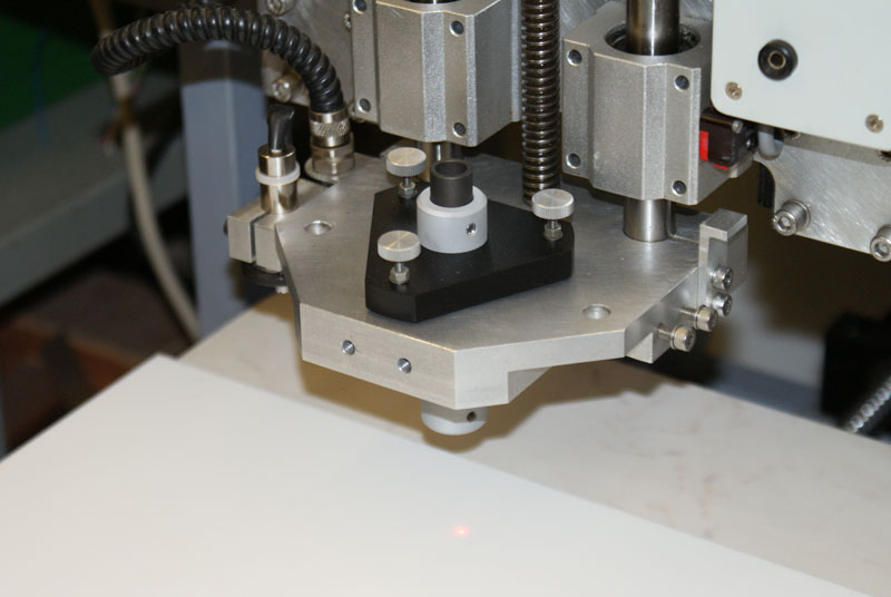
The cooling water header tank was bit of a problem as, at the time, I could not find anything ‘ready made’ that was really suitable for the job so I fabricated this one from glass fibre tube and sheet.
This was my initial thoughts on the wiring that would be necessary to connect everything and provide for switching the laser (on/off) from the computer. There were a couple of changes made in the light of experience (the test switch and is associated resistor was not required nor was the 9V supply to the tube current display) but it is the circuit I am currently using.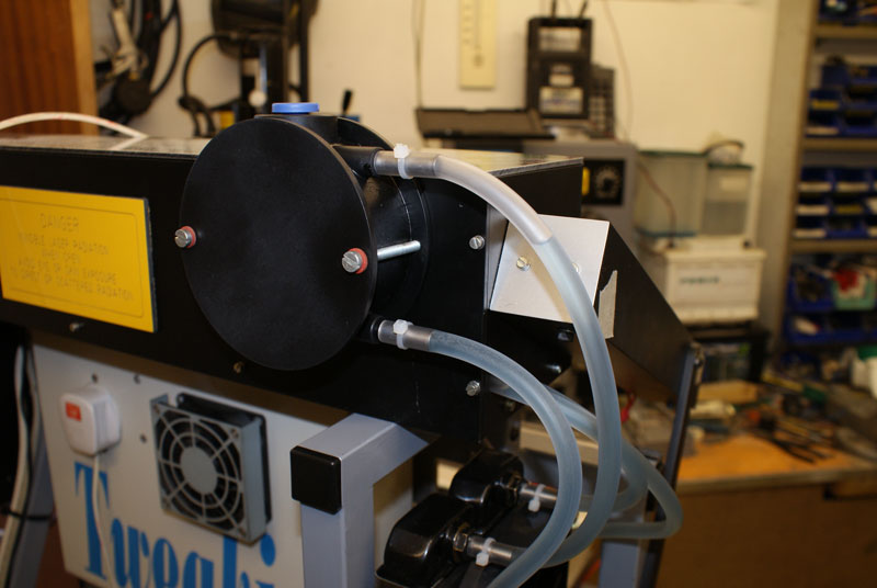
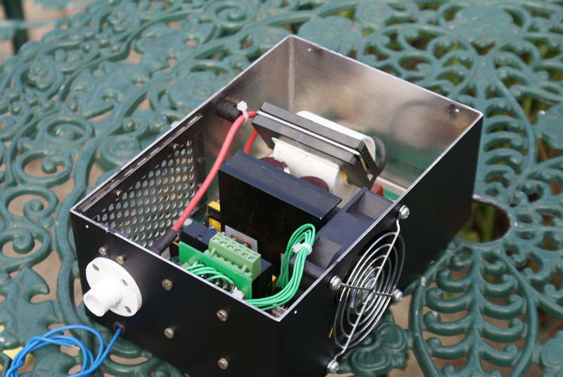
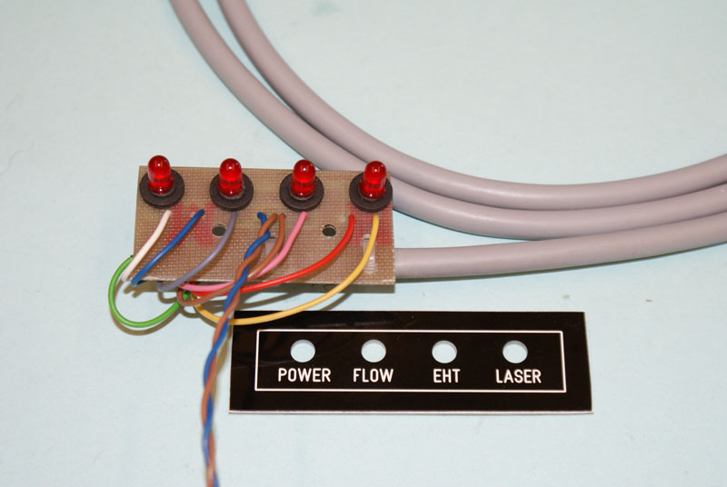
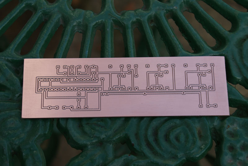
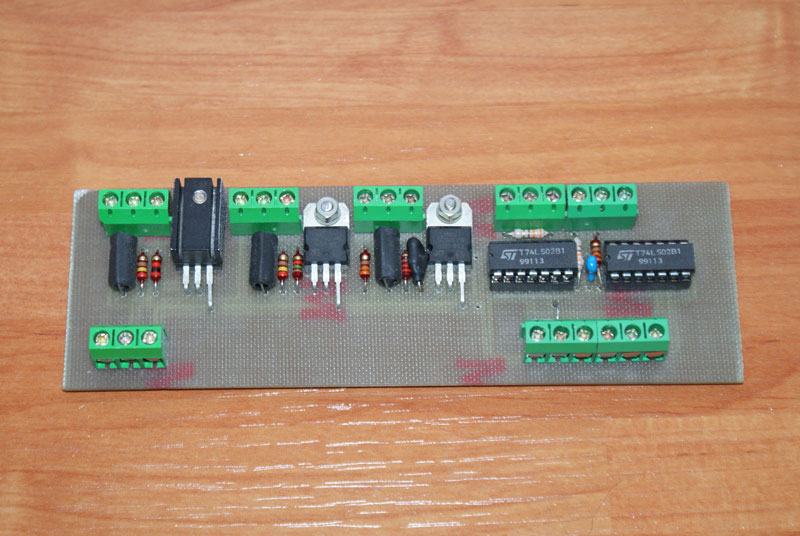
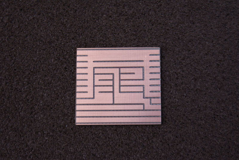
A couple of small circuit boards (one for the control circuit / voltage regulators and one for the display LED’s) were isolation routed, assembled and fitted into position on the enclosure which surrounds the laser tube. The 12Volt voltage regulator which supplies the fans and pump was fitted to a larger heatsink and mounted separately.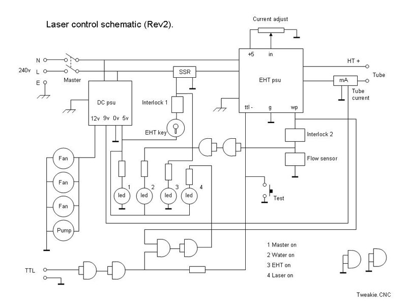
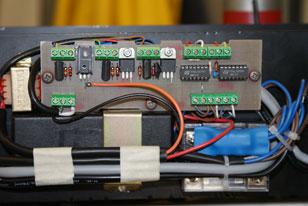
As it turned out, the digital display for the tube current was not a success (can’t expect to get everything right first time) as it failed to work correctly at low current settings and failed to average the current when the tube was operated in pulse mode so it was later swapped out for a good old fashioned analogue meter.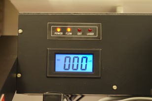
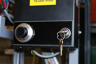
The tube’s actual output power is normally controlled from the operating software but for tube safety reasons I still retain manual control of the maxim current available with the use of a 10 turn potentiometer, with locking dial, fitted to the high voltage PSU’s front panel. This is also where the safety ‘lock-out’ key switch has been fitted. The panel is intended to be engraved with a suitable legend but this is still work in progress.
Life is too short to take everything seriously and there always has to be time for some humour. Poor little Super Kitty (my avatar) took a bit of stick over this one.
On a serious note though...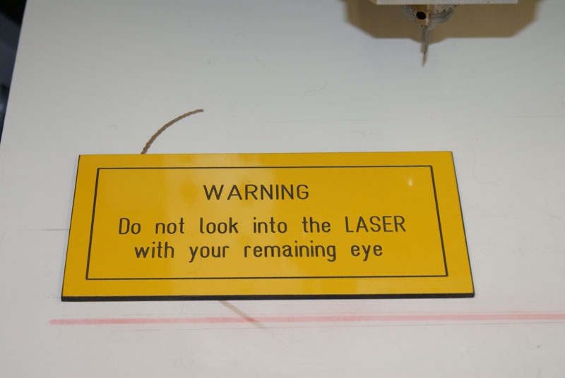

Only a fool would enter a construction site without wearing a hard hat. Only a fool would operate machinery without the guards in place. Likewise only a fool would operate a laser without wearing suitable eye protection.
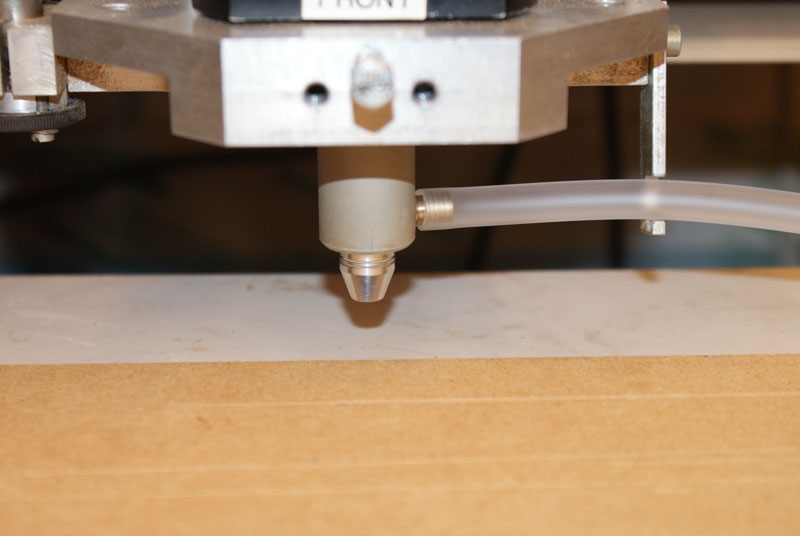
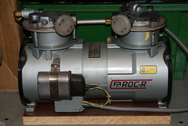
When cutting with a laser ‘air-assist’ is generally necessary, to clear the kerf of carbon deposits, and in my build this has been provided by a small, oil-less, koi pond pump which has been fitted to the side of the machine frame and piped to a ‘nozzle’ forming part of the focus lens assembly. The air assist is then applied co-axially with the laser beam exiting towards the work through a 3mm diameter bore nozzle. Some materials, such as MDF, require higher air pressure when cutting and this is provided on an ‘as and when’ basis by a slightly larger, free standing, oil-less, Roc-R pump.
The ‘air-assist’ also serves another purpose – it keeps the focus lens cool as well as protecting it from particles, vapours and smoke. As this air is in contact with the lens it is necessary that any compressors / pumps used are of the ‘oil-less’ variety – any oil settling on the lens would almost certainly damage it (or it’s AR coating).
Obviously there are lenses and there are lenses and it is only when you have used a quality US manufactured lens that you appreciate the difference over a cheap Chinese manufactured lens. There is also a huge difference in price and I certainly don’t want to be purchasing any replacement lenses unnecessarily.
Perhaps one of the most important personal safety concerns when actually using a laser, which is often totally overlooked, is one of fumes, particles and vapours. Many materials when burned can give off extremely toxic fumes and could cause us serious health issues if inhaled.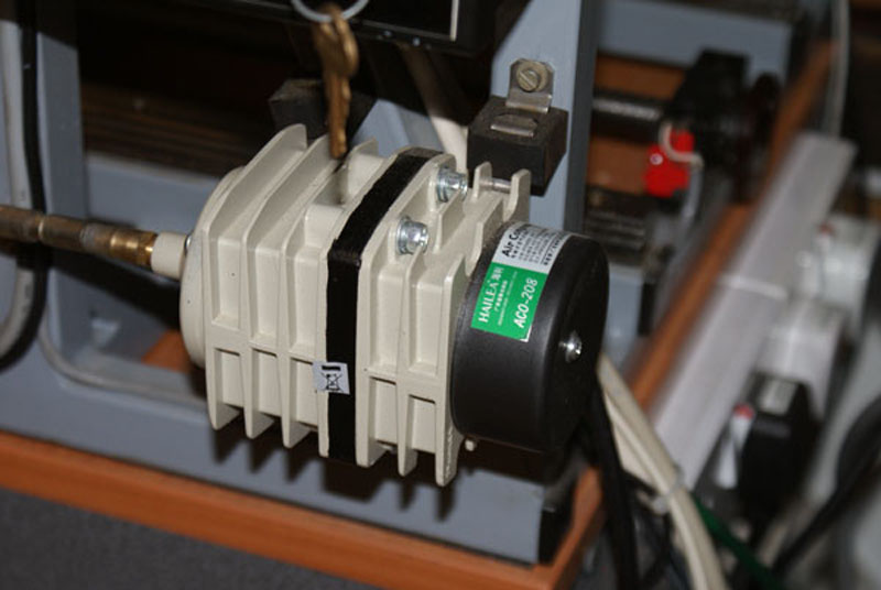
As an example PVC when cut with a laser will give off chlorine gas which when combined with the natural moisture in the air creates a form of hydrochloric acid. This will rust ferrous machine parts and damage plastic parts (although the effect is not immediately apparent – it will happen) so who knows what it will do to us if inhaled. In the US there is an obligation for suppliers to provide the constituents of materials sold but this does not apply here in the UK and many of the materials we commonly cut with our lasers can give off totally unknown gasses and particles.
Fume extraction is therefore a must and I have an overhead, ducted extraction system in my workshop which is more than adequate for the task. It is not certified as being ‘intrinsically safe’ so no assist gasses (such as Oxygen) are ever used with the laser - just compressed air.
Another very important personal safety concern, when using any type of laser, is one of fire.
Whilst using ‘air-assist’ does, to a large extent, reduce the chances of a ‘flare-up’ the risk is always present so suitable precautions must be taken in advance for dealing with a fire should one occur.
Obviously, keeping flammable materials away from the laser area – having a fire blanket and a suitable fire extinguisher close to hand would be sensible precautions but every installation will be different so an advance survey of the area should always be undertaken. Leave nothing to chance and be safe.
This is my MkII fume catcher which easily fits to the machine and is piped into the ducted extraction system.
Because the possible fumes produced when laser cutting may be invisible to our eyes the efficiency of the new catcher was tested using smoke pellets (commonly used for testing flu liner installations in heating systems). Tests showed a total capture, over the whole working area, of the white smoke produced by the pellets so I am now more than satisfied that this will be an effective system for my machine.
Once the laser was up and running this is a short video of the first GCode test sample made. It is nothing special and it was done some time ago but it still holds a place of honour in my collection of samples. http://www.cooperman.talktalk.net/laser1a.wmv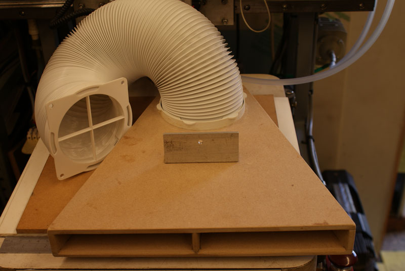
How to fully control the laser was next on my agenda. I use Mach3 as my machine control software and found the usual GCode M3 / M5 commands too slow to be of any real use but in conjunction with the software owners work was done to develop the undocumented M11P1 / M10P1 commands. This command set will switch on / off Output #1 at the exact time of an axis (any axis) movement (in a similar way to an axis direction pin signal) and proved to be just brilliant for laser control. The Wile E coyote shown in the above video was produced by converting the vector drawing to GCode then operating the laser in continuous (CW) mode, at a preset maximum current, using the M11P1 / M10P1 command set.
My laser can also be operated in pulse mode, a method which I find preferable, and this is achieved by using Pulse Width Modulation (PWM). This is a brief resume describing how it can be manipulated and where appropriate, I have included the full title of the various acronyms solely for the benefit of those who are not yet familiar with these abbreviations.
PWM is essentially a stream of rectangular, digital, pulses comprising of three separate components –Amplitude, Duty Cycle and Frequency.
Amplitude is never a variable and it is generally fixed at 5Volts but for some, later, equipment this may be at the more recent TTL (Transistor – Transistor Logic) standard of 3.3Volts.
Duty Cycle is usually expressed as a percentage and it is basically the ON / OFF time of the switching signal. For example; with a 50% Duty Cycle the laser output is on for half of the time period and off for the remaining half of the same time period. However, as the variable component in the Duty Cycle is the Pulse Width then Duty Cycle can, on occasion, also be expressed in terms of time – typically in uS (microseconds).
Frequency is the number of times per second the Duty Cycle is repeated. This component is commonly termed the PRF (Pulse Repetition Frequency) and is generally expressed in kHz (kilohertz). The frequencies most commonly used are between 5kHz and 20kHz with 20kHz (20,000Hz) being considered to be the upper operating frequency limit for most laser Power Supply Units (PSU).
The following diagram depicts a typical PWM waveform (as would be seen using an oscilloscope) and this is essentially a graphical representation of Voltage versus Time.
As most (not all) laser PSU’s operate from an Active Low signal, in this and the following examples, the area above the graph (as shown by the shaded portions) represents the laser ON time.
As the speed of light is (essentially) a constant, in the above example, we are unable to change the 12.5 kHz PRF without it changing the 80uS time period of one complete cycle and visa versa because Frequency and Period are reciprocals of each other but there are two distinctly different ways in which the laser ON time and thus the apparent laser output power can be controlled by manipulating the PWM.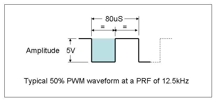
Consider the following example where we initially have a 25% Duty Cycle and we wish to double this power output setting to 50%. We could either double the pulse width from 50uS to 100uS or we could keep the pulse width at 50uS and double the PRF from 5kHz to 10kHz. Both these solutions will result in a 50% Duty Cycle.
Quite obviously there are an almost infinite number of combinations of Pulse Width and Frequency which we could use to achieve a 50% Duty Cycle but, depending on the material being worked, each combination may produce different results in the finished product. Bit of an abnormality perhaps but there are reasons for this behaviour, possibly to be described at a later date.
There are constraints on the manipulation of PWM (to avoid a situation where the safe internal photon density of the tube is not exceeded) but provided the Frequency does not exceed 20kHz and the manufactures recommended maximum tube current is not exceeded then almost anything goes.
Commercial laser machines generally incorporate safe settings limits within their software / firmware to prevent the user from accidentally over-driving the tube and for this reason it should be considered most unwise to override or change any password protected settings found on those machines.
As with everything, there will always be exceptions. For example, my DC excited laser (described in this build) can be operated at 100% PWM which is essentially CW (Continuous Wave) mode but only because it has a preset ‘maximum tube current’ control. My RF excited laser does not have this option so 95% PWM is its maximum safe limit. With both types of laser my highest operating Frequency is still regarded as being 20kHz.
Just as an example of how I use PWM manipulation...
These two images (laser burned into wood) look pretty much the same at a distance however, the method used for laser control can play an important part in the results that can be obtained.
The first has been created by the more usual process of ‘Dot-Dithering’ where the original 8bit photo image is reduced to 1bit and equal sized dots, pseudo-randomly placed to create the illusion of shade, are burned into the wood with the laser operated in TTL mode.
The second has been produced by controlling the PWM. The actual Pulse Width is fixed and the Pulse Repetition Frequency has been varied (between 0Hz and 12.5kHz) in accordance with the original photo image’s 8bit pixel value.
As said, they both look pretty much the same at a distance but when viewed close-up there is a world of difference.
Lithophanes can also be produced using exactly the same variable PRF technique of laser control as used with the previous example.

Initially I did not think that laser produced litho’s would be a match for rotary engraving but was pleasantly surprised with the result. The big advantage of using a laser for this type of work is one of speed – Lithophanes that used to take me hours with rotary engraving now only take minutes with the laser. I still have some more work to do in perfecting the technique (there is still a lot to learn) but it is improving all the time.
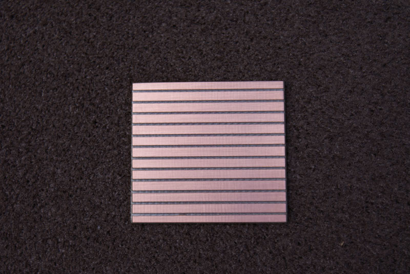
As an example of the detail that can be produced this litho of the Hungarian parliament building was laser cut into ivory Corian and measures just 50mm square.
Lasers are, by nature, extremely fast acting devices and the conventional M3 / M5 spindle control codes are often way too slow acting to be of much use when doing fine engraving work etc. To overcome this, the Mach3 code set M11P1 / M10P1 has been developed to switch the laser on / off at the exact moment of axis movement. However, if using PWM to control laser output power some extra trickery is required and this is described here.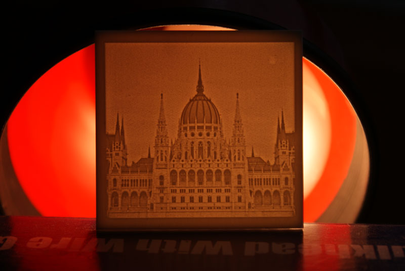
A pre-set CO2 laser output power is not a constant – it will vary dependant on tube temperature and it’s cutting / engraving ability will also vary dependant on ambient temperature as well as the type of material and it’s moisture content etc. etc. As a result a GCode program with a defined power setting may run just fine today but may need some adjustment to run just as well tomorrow.
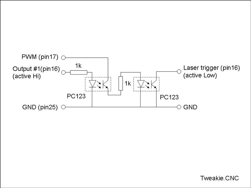
There is always more than one way to accomplish anything but this is the best solution I have come up with so far. It does however need a bit of extra hardware to function but this is simple enough to make and just fits inline with the LPT cable to the machine.
The maximum laser power is still manually set and the GCode Sxxx command controls the actual laser output power between (approx.) 0% to 100% of the maximum that has been set. This allows for the laser output power variations, mentioned above, to be compensated for and adjusted on a day-to-day basis without having to make any changes to the GCode program.
The extra hardware basically gates together the Mach3 PWM signal with the M11P1 / M10P1 command codes on Output# 1 just by using a pair of opto-couplers and the LED series resistor values have been chosen to present a loading on the LPT port of no more than 5mA per pin which is well within it’s capability.
This method negates the set-up time delay associated with switching the PWM signal with the M3 / M5 commands by leaving the Mach3 PWM signal constantly running then just applying it as required with the M11P1 / M10P1 commands. Provided any changes to the laser output power are commanded by entering the Sxxx command on a separate line in the GCode no delays in changing power levels have been noticed and engraving / cutting within the same program is easily accomplished.
The circuit is extremely basic and can be easily made and fitted to an existing machine (which is controlled by the LPT port, of course) and the following pics. Show just what I have done.
My Mach3 set-up is as follows (please note - your pin numbers may be different).
PWM base frequency 500
Minimum PWM 0
Relay – M3 Output #2
Spin up / down delays all 0
Spindle √ 17 0 X X 1 1
Output #1 √ 1 16 X
Output #2 √ 1 9 √
Spindle pulley 1 Min speed 0 Max speed 100 Ratio 1
So basically, the GCode program uses M3 followed by Sxxx (0 to 100) which is essentially percentage of full power. Thereafter changing power by entering a new Sxxx command and the laser is switched on / off, during the program run, by the M11P1 / M10 P1 commands. The program then has M5 to switch off the PWM signal at the end.
Some further thoughts on this…
By changing the active state of Output #1 to ‘active low’ the circuit can be simplified as shown below.
A short, 1 minute, video of the laser in action whilst doing some testing with Mach4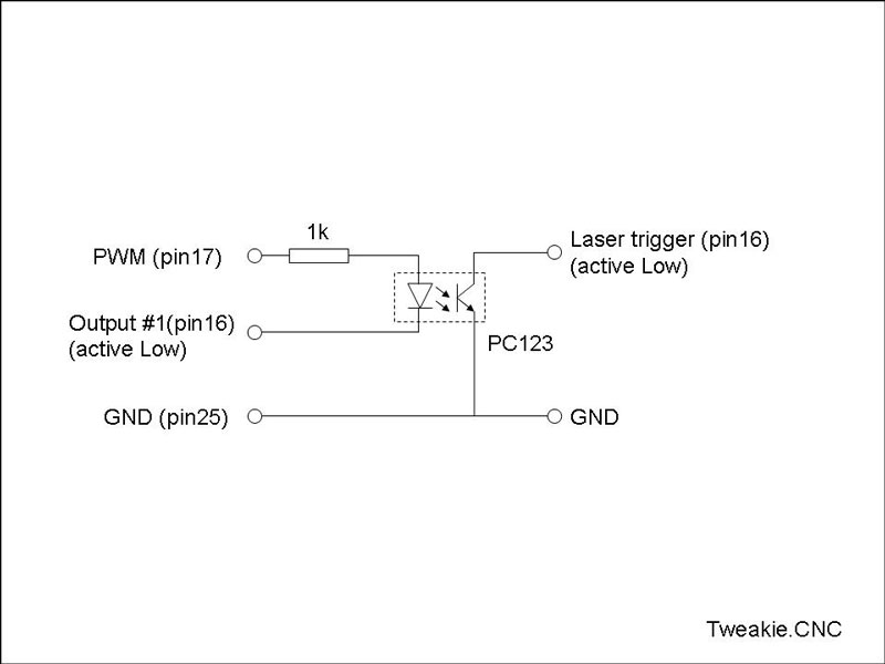
http://www.graytel.talktalk.net/Darwin 2.wmv
Tweakie.
To be continued...
CO2 laser.
Build in 'LASER - PLASMA BUILDS' published by Tweakie, Jul 10, 2014.
Here it is my intention to show what was involved in adding a CO2 laser to my existing CNC machine.
-
-
Build Author Tweakie, Find all builds by Tweakie
-
- Loading...
-
Build Details
- Build License:
-
- CC - Attribution Share Alike - CC BY SA