CNC-machine 650by700, designed and made by Carl Siren
The frame
I chose to use steel profiles for the frame. Two 650 mm long 125x65x5 L-profiles were placed on the sides in the direction of the y-axes and one 850 mm long 125x65x5 L-profile on the back side in the direction of the x-axes. Between the profiles on the sides were two 700 mm long U-profiles placed “upside down”. I drilled holes, painted the steel profiles black to give the CNC-machine a better look and finally joined the steel parts together with M6x25 bolts and lock nuts & shims.
A 24mm thick plywood board 700x650 mm was placed on top of the U-profiles. The use of this thick plywood helps to make the frame rigid, exactly the right size with absolutely straight corners. I fastened the L-profiles with M5x60 wood screws into the edges of the plywood –four screws on the sides and three on the back side.
On top of the plywood board are four 175x15mm aluminum profiles fastened. The aluminum profiles have 6.4 mm wide t-slots 50mm apart. I used M6x60 mm stainless steel machine screws with counter sunk heads. Each profile has four of these screws in two rows attached to the U-profiles underneath the plywood (the two rows of counter sunk screw heads can be seen in both pictures on the first page).
The C-Beam Linear Actuators
The y-axis consists of two parallel 650mm long C-Beam Linear Actuators, one on each side of the steel frame.
The x-axis (abt. 800 mm long) is connected to a 385 mm long vertically placed L-profile 125x65x5 on each end. Rectangle shaped corners 125x65 mm were cut out of the lower inner part of each L-profile. The connection to the y-axis Linear Actuators is made with XL Gantry plates with six (mini V Xtreme) wheels each.
The z-axis is connected to the x-axis with two XL Gantry plates, one plate with three wheels in two rows horizontally (the one moving along the x-axis) and the other with the wheels in two vertical rows. I enlarged four of the holes in the plates and attached the two plates with counter sunk M6 x20 machine screws and lock nuts.
The Electronics
The CNC xPro V3 was chosen as the axis Controller. I placed the xPro inside a black enclosure box which was fastened at the rear side of the frame. I equipped the power supply cable with a 15A fuse to avoid damaging the controller board with over-current (The V3 has a built in TVS Zener diode as over-voltage protection).
All axes have NEMA23 (model MT-2305HS280aW-C) stepper motors with a torque of 12.6 Kg-cm and max current draw of 2.8 A. Each motor is attached with an aluminum Bracket Mount and four M5x60 mm low profile bolts.
The power supply is a Dc 24 V (230 V AC, 350 W) Power supply from eBay. I detached the cover plates and painted them black to better match the steel frame on which is fastened.
The Router
For the CNC-machine I bought a router (a 1,5 kW Air cooled spindle motor with an ER11 collet set) on eBay. The router came with a 1-3 phase AC Huanyang HY01D523B Inverter (230V, 50 Hz, 1,5 kW). The maximum speed of revolution of the router is 24 000 rpm and this is achieved with 400 Hz from the Inverter. The Inverter (or frequency converter) is attached to the vertical L-profile on the left end of the x-axis. Underneath the Inverter is a connection box which contains a power EMI filter. A shielded cable is installed between the Inverter and the spindle motor.
The spindle motor is attached to the z-axis linear actuator with a 160x100x4 mm “adapter” steel plate. The plate has 20 drilled holes, 8 for M6x25 screws to connect the plate and the motor and 12 for M5x10 low profile bolts attaching the plate to the C-Beam profile.
Testing and parts made on the machine
I installed two end switches in parallel on each axis and got the homing process working nicely. The maximum travel between the soft stops for each axis (values $130, $131 and $132) are set to 560 mm for the x-axis, 480 mm for the y-axis and 105 mm for the z-axis. I set G28 0,0,0 (my tool change position) near the homing position at the top left back corner on the machine and G30 0,0,0 at the opposite corner at the (lower right corner at the back of the machine). I managed to set origins for Work Coordinate Systems G54 – G59.
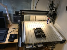
So far I’ve mainly run tests on my CNC-machine. Most of the tests were done by entering G-code commands in the command line of Chilipeppr grbl work space. The machine cuts plastic, wood and other soft materials nicely. I managed to do some test cuts in aluminum and even one in cast iron with shallow cut depths and really conservative feed and speed. In this test I used Autodesk Fusion 360 to design a modification to a key seen in the picture below.
I’ve managed to make a few parts on my CNC-machine. I used Autodesk Fusion 360 to design them and to generate the G-code. I sent the G-code to the machine with Chilipeppr. The first usable part made for the CNC-machine itself was a “holder” for a LED lamp around the spindle. I ordered a pair of 70 mm diameter “Angel eye” LED Halo rings and glued one of them on to the “holder” to make the lamp.
Nearly all of the parts I’ve made have been held in place with an old 4” machine vise bolted to a piece of plywood fastened with M5x50 screws to the t-slots in the machine table. The distances between the screws allow the vise to be turned in four different directions on the table.
Modifications and add-ons
The first connection between the X- and Z-axis was made by two regular sized gantry plates with four (mini V Xtreme) wheels each. This resulted in some unwanted motion of the Z-axis. I replaced the gantry plates with the XL ones and the rigidity of the Z-axis was improved a lot. Another modification that had to be made was that I needed to shorten the Linear Actuator of the X-axis. I originally ordered the parts form Ooznest in the UK (the official reseller of OpenBuilds in Europe which has this great service of cutting the parts to the length you need). I ordered my X-axis Actuator about 15 millimetres too long so I had to cut it myself. When I reassembled the X-axis I decided to fasten the ends of the C-Beam profile through the vertical steel L-profiles. Originally the C-Beam profile was only fastened from the back with eight M5x10 low profile bolts into four double tee nuts at each end.
To prevent the chips from flying all over the work station I added three 200 mm high clear Acrylic sheets around the work space of the CNC-machine. A 600mm long LED light fixture is attached to the bottom of the C-Beam profile of the X-axis Linear Actuator. All wiring is situated in Cable Drag Chain Carriers or underneath slot covers in the C-Beams
I drilled holes for a 10 mm copper tube going through the U-profiles at the bottom of the frame. The tube is a part of a pneumatic system for chip removal. The air from an Airbrush Compressor is fed from below to a T-connection in the middle of the steel frame in the back of the machine. The air goes horizontally into the copper tube to the front of the CNC-machine and vertically into an 8 mm hose connected to a fixed air nozzle attached to the spindle motor. At the front of the CNC-machine is another T-connection. From this T-connection air is divided to a hand held air blow gun to the right and to a 3-position 4-way air valve. With this air valve I can control pneumatic dual acting cylinders used in clamping systems.
One thing I’m currently a bit pensive about is the fact that the current draw of the stepper motors could be as high as 2.8 A but the maximum output current from the CNC xPro board is 2.5 A. I haven’t tested yet with an ammeter how much the actual current draw is in real time. So far the torque of the stepper motors appears to be enough for the chosen feed rates to create decent round or rectangular shapes. Another thing that I need to do is to figure out how I can get the xyz position of the tool to be visible in the Axes widget in Chilipeppr.
CNC-machine 650by700
Build in 'CNC ROUTER BUILDS' published by Carl Siren, Feb 4, 2018.
A home-made CNC-machine with a 1.5 kW air cooled spindle motor suitable for milling materials such as wood, plastic and soft metals. The work table is 650 mm wide by 700 mm deep and the maximum movement is set to 560 mm for the x-axis, 480 mm for the y-axis and 105 mm for the z-axis.
-
-
Build Author Carl Siren, Find all builds by Carl Siren
-
- Loading...
-
Build Details
- Build License:
-
- CC - Attribution - CC BY
Reason for this Build
The preliminary need for the CNC-machine came from my hobby building electronic devices. I needed to modify plastic enclosures (i.e. embed LCD-screens and openings for sockets, make acrylic boards to hold PCBs, batteries and other components inside the enclosures) for my different projects.Inspired by
Many different builders such as Martin Turner: -
Attached Files:
Parts list
Qty Part Name Part Link Comments 1 Steel L-profile 125x65x5, 850 mm long Link Frame profile 2 Steel L-profile 125x65x5, 650 mm long Link Frame profile 2 Steel L-profile 125x65x5, 385 mm long Link Frame profile 2 Steel U-profile 80x40x4, 700 mm long Link Frame profile 6 Steel corners 40x40x2 Link Frame accessories 1 Steel plate 160x100x4 Link Steel plate to connect z-axis Linear actuator with spindle motor 1 C-beam linear actuator kit, 800 mm long http://ooznest.co.uk/3D-Printer-CNC-Kits-Bundles/Linear-A... Link C-beam actuator kit for the x-axis 2 C-beam linear actuator kit, 650 mm long http://ooznest.co.uk/3D-Printer-CNC-Kits-Bundles/Linear-A... Link C-beam actuator kit for the y-axis 1 C-beam actuator kit, 300 mm long http://ooznest.co.uk/3D-Printer-CNC-Kits-Bundles/Linear-A... Link C-beam actuator kit for the z-axis 1 Plywood board 650x700x24 Link 4 Aluminum t-slot profiles 175x15, 650 mm long Link 1 Link This is only a parts list for the main components. Please see the separate pdf-file for a complete parts list! -
Attached Files:
-


