
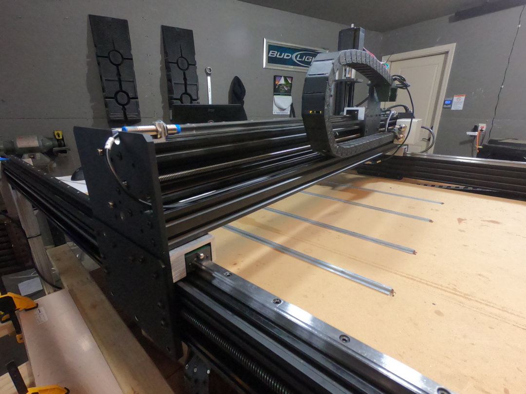
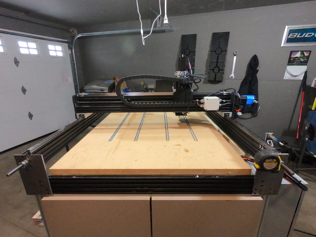
While diving into the Journey of making my Workbee 1510 a complete Lead Screw and Lineal Bearing machine I encountered an issue with my motors not having enough torque to move the machine. Easiest solution... Get larger Steppers of course, but it didn't end here, as it never does!
Manuals on Parts that I used are in the Files Tab.
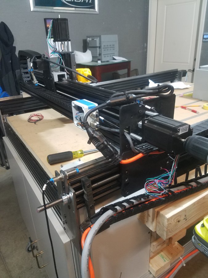
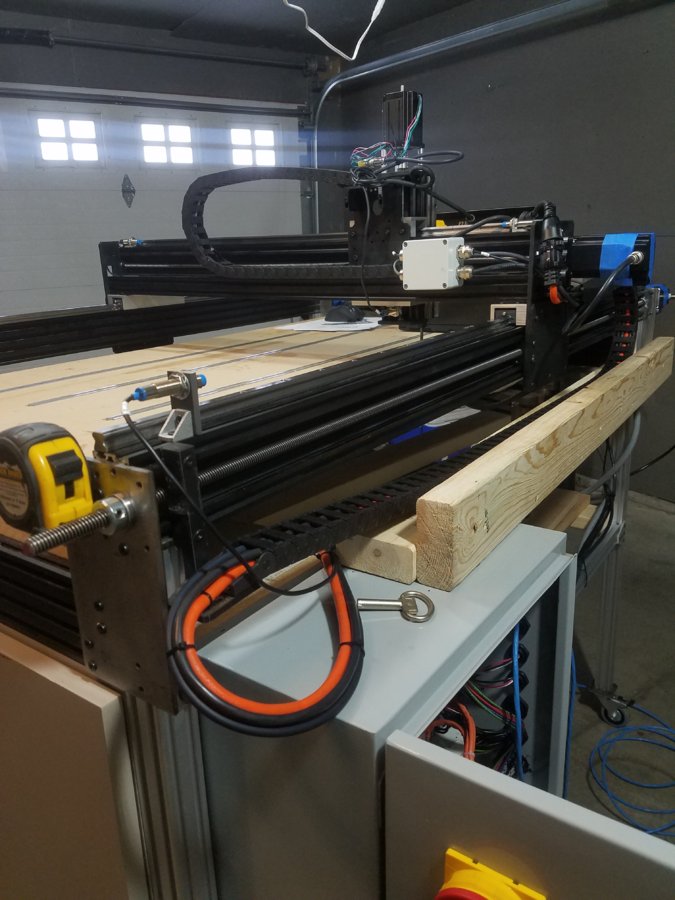
With the addition to larger 425 oz/in steppers (which I am still not certain will work yet, crossing my fingers) I will need drives, and if I am doing this project I wanted to go above and beyond and buy a Ethernet Smooth Stepper too.
To start I bought the majority of my products at CNC4PC, which in all honesty has been more trouble than anyone deserves as I didn't receive anything until 3 weeks later, on top of that they forgot 1 of 4 motor end cap so I can use plugs, as well as I received 5 6foot cables instead of 4? Which in turn they forgot to send the 8foot and 12foot I had also ordered.... Im sure it'll be another 3 weeks for those. Just want people to know how organized this place is. RANT OVER.
Parts List in the designated tab
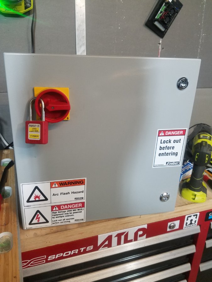
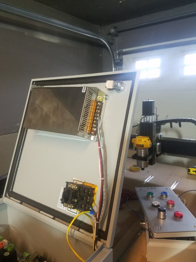
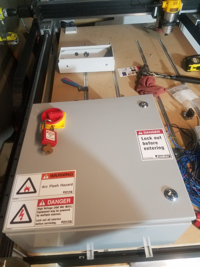
I Started with the Cabinet that I had purchased from Hawk Electronics. I chose this because I wanted an industrial looking enclosure with a solid galvanized backplane. next was to get a Proper Disconnect made by Moeller that I purchased on Ebay. It provides Proper Lock Out Tag Out, remember I want this to be a Industrial Looking enclosure. As a rule of thumb and industry standards, typical 50vDC or below is not required to lock out whereas 120vAC + is required to lock out before servicing. since this cabinet does have 120vAC, I placed some extra safety stickers I had to the cabinet. Don't worry 480vAC is not in this cabinet, But future CNC's I would like to build might

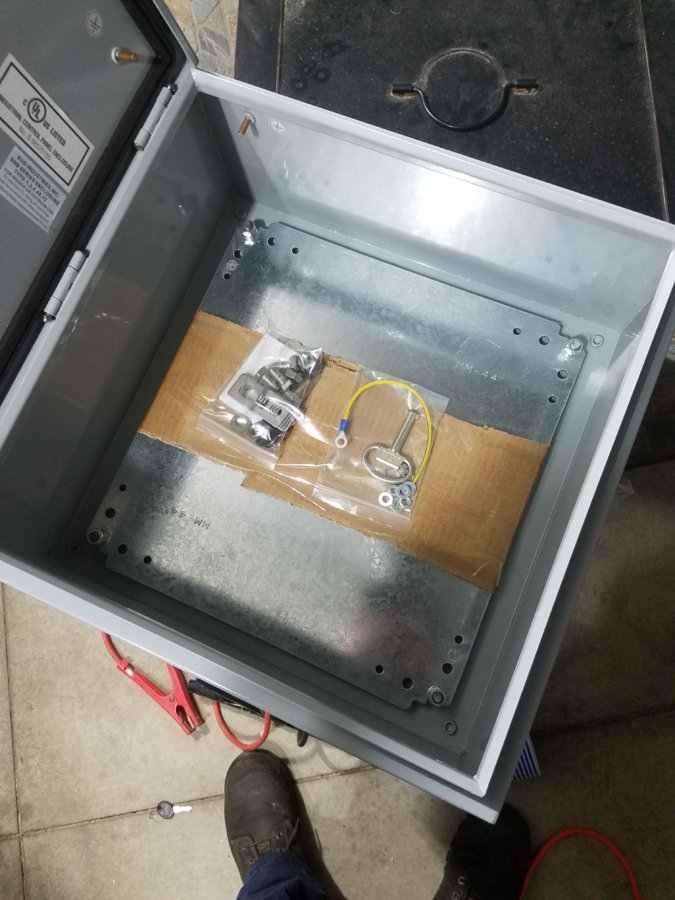
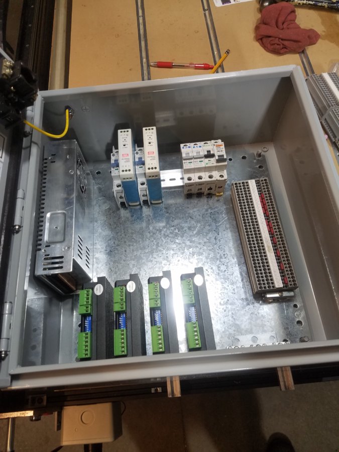
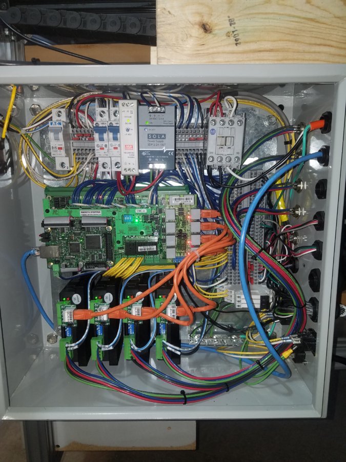
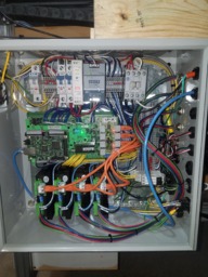
The general layout was a bit hard to decide on as I wanted to isolate the AC from the DC as much as possible, and if they do cross, they must be perpendicular to eachother. Another good rule of thumb if need to be to have AC and DC power wires away from eachother, but they can intersect at around 90 degrees if need be, This will cause no issues. This layout worked for me as the AC is in the top left of the cabinet away from the DC voltage, with the exception of the contactor for the spindle run. But these wires were crossed perpendicular. I also had no option but to put the 48vDC power supply on the door, but I actually like it.
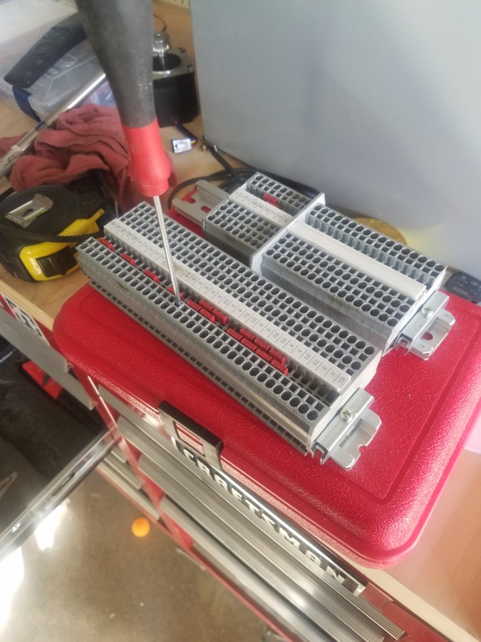
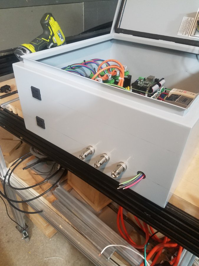
I ran all of the inputs and outputs to terminal blocks that I had because well, why not! it provides easy troubleshooting for whom who built the system, and also ease of anyone else who works on it, if proper prints are made...which there will be. I also love these terminal blocks for their ease of power distribution with jumpers, But the newer Phoenix Contact Blocks are nicer than these. I also have always hated screw terminal blocks, I Can't tell you enough how many times I've seen issues on machines by poor terminal block interface screw connections as they loosen over time due to heat.
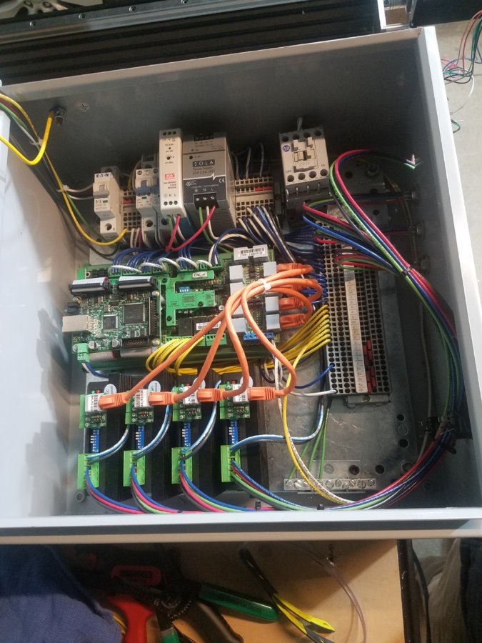
Then just to wire everything up!!! And this is what my semi-final wiring looks like. I have not yet wired the Power in connector, Recepticles, and the last motor (waiting on connectors), and punch holes for the Cord grips for all the limits. But will hopefully get the rest of the parts and finish this by next week.
1/22/2019 Update
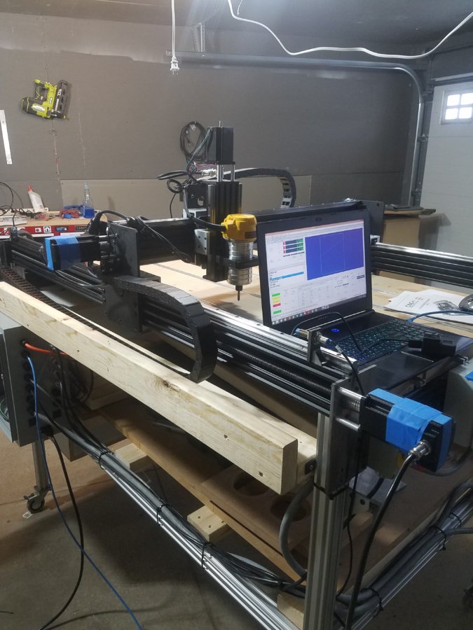
Still Waiting on Another motor cover for the Z axis as well as the screws for all the covers... Hence the blue tape
If anyone uses the same controllers as This I would be able to assist you with the configuration files, Screen Editor Questions, and PMC questions.
Finally finished Taking some pictures of the final Product!! Everything is wired up, configured, tuned and tested.
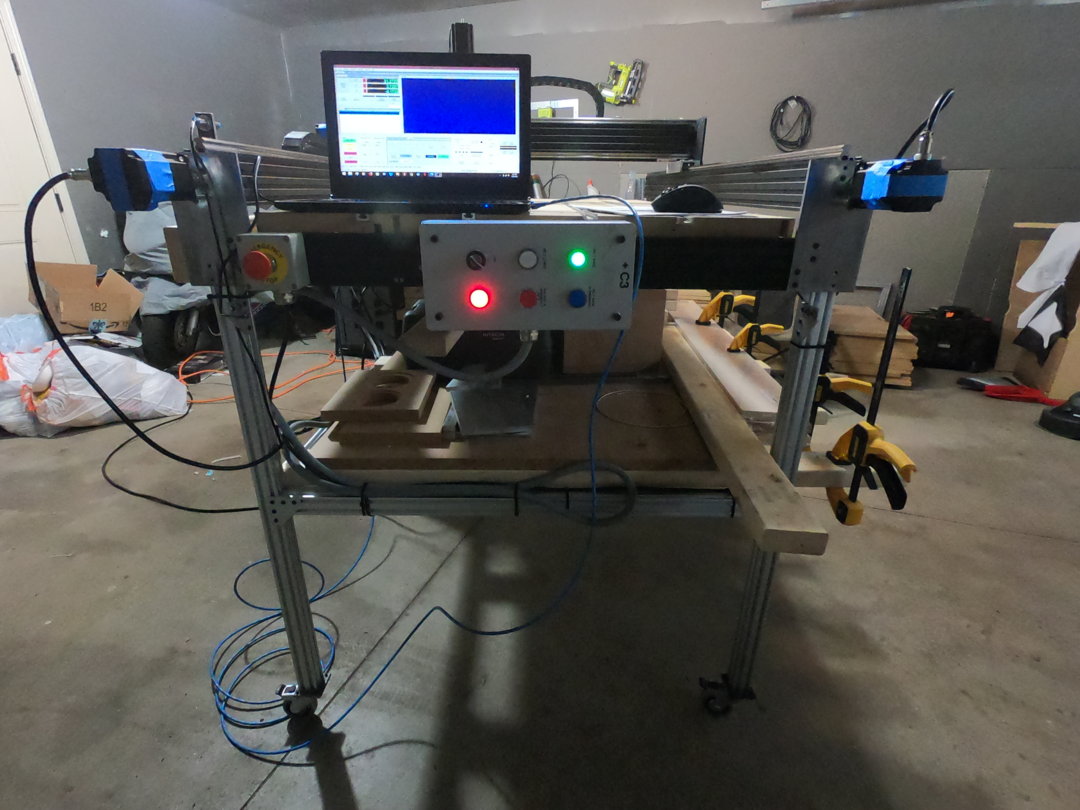
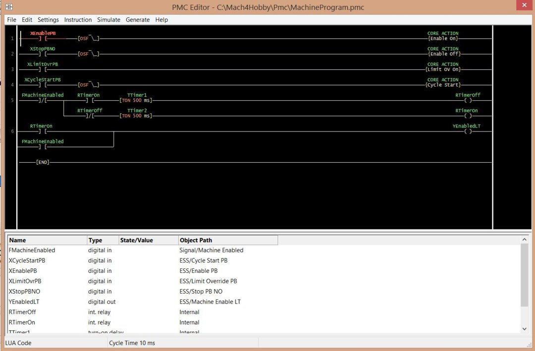
Installed the Ops console back on and Configured it through the PMC editor in Mach4.
1. What It does is when the machine is not Enabled, the Green Light will flash every 500ms.
2. When the enable button is Pressed The machine will enable and the light will go Solid green. The machine enabled output contact will be placed before the Flashing Rung to disable it when the machine is enabled.
3. When g-code is loaded, Pressing the White button will Start the Cycle. When a Cycle is active the White light will be ON
4. Pressing and holding the Blue button will override the Limits and the Light will be turned on indicating that the Override is on, even when pressing it in the Mach4 Program
5. Pressing the Red Fstop button will disable the machine, which also performs a cycle stop.
6. The Red light indicated power present within the console.
7. The selector Switch Disables power to the Console for Service.
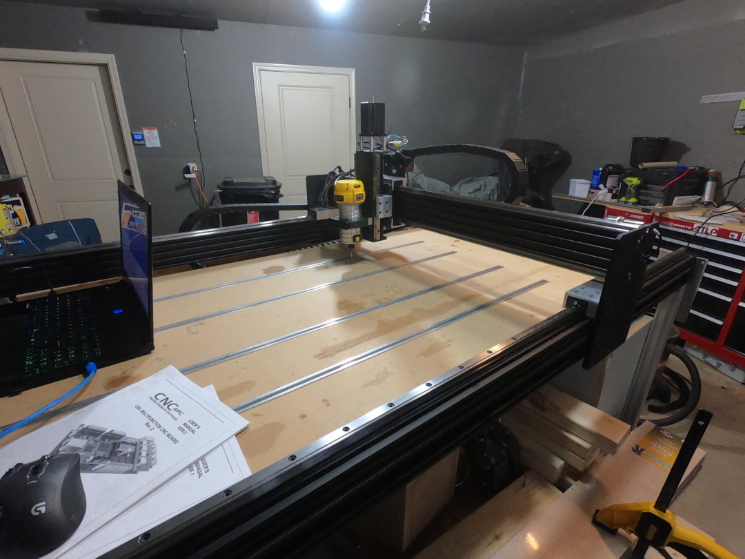
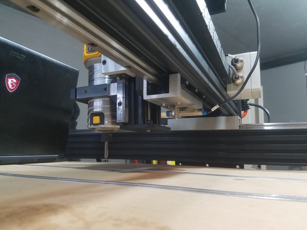
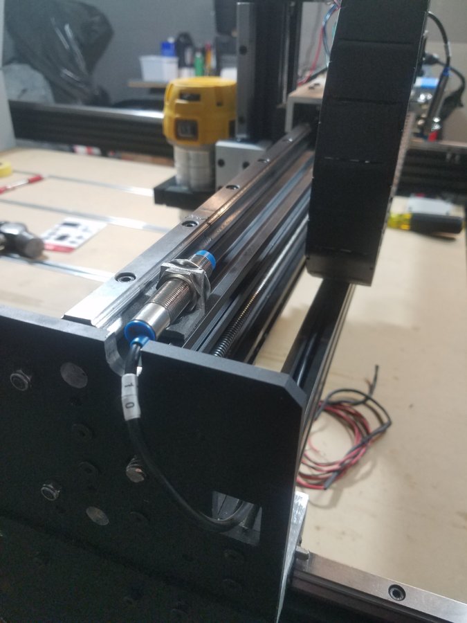
Mounted the z-Axis Limit to the bottom of the linear bearing block. Works nicely.
CNC ESS Controls System
Build in 'Everything Else' published by Jacob Lotter, Jan 22, 2019.
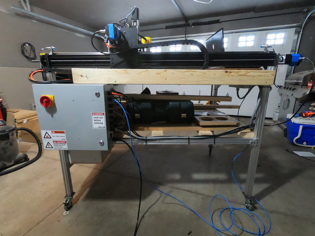
My Controls box to run my Workbee 1510 That was retrofitted with Lead Screws as well as Lineal Bearings. The stock electrical configuration was not enough, so here are the Measures that I took to not only make this machine Run again, but to have fun with it, and make this system be able to run any CNC I run in the future with the installed microcontroller.
-
-
Build Author Jacob Lotter, Find all builds by Jacob Lotter
-
- Loading...
-
Build Details
- Build License:
-
- CC - Creative Commons Public Domain (CCO 1+)
Reason for this Build
I wanted a controls box that I could disconnect easily, and add to any other CNC with relative Ease. I should have this system for years to come. -
Parts list
-
Attached Files:

