
What’s up Y’all!! I’m super excited about this new project/toy. I ordered the brand new ACRO system from the Open Builds Part Store. It’s a brand new machine bundle from those guys. My Black Widow 3D Printer utilized Open Builds parts and I really like it and feel very comfortable with it. I planned for this laser to be just like my popular (for me) last laser engraver that I upgraded to laser cutter except giant. I was contemplating back and forth about whether or not to order it and I had had a rough day at work and My Lady said go ahead and so it was a vulnerable combination for me and my wallet. Haha. I ordered the version that is 1500mm by 1000mm on the aluminum extrusion. I haven’t fully figured out how big the build area will be quite yet, but it’s pretty huge. I can fit a 2' x 4' sheet in there and it's not nearly maxed out. I used this z axis ball screw and I attached this 5.5W laser to it. With being able to cut through wood with a 2.5W laser, albeit very slowly, I’m super excited for what I’ll be able to do with 5.5W. Instead of using mechanical endstop switches for the x and y axes, for this one I thought to use inductive switches. I used the same type of laser controller that I reconfigured on my other laser cutter. It is basically a controller meant for a 3D printer with reconfigured firmware to accommodate laser engraving or light CNC machining.
Using the ACRO build instruction video, this machine was incredibly easy to assemble. I had it mechanically built in one evening after work. For the following couple of pictures the controller is still not in a box, so it’s a serious mess in the middle while I’m still configuring all of the settings. Here are a couple of the initial shots:
So for those of you metrically challenged like me, 1500mm x 1000mm is huge. I had to set almost a whole sheet of melamine on top of my desk so just to get it assembled and configured. Once it was mechanically assembled I added the inductive endstop switches. A quick note on these inductive endstop switches. I went on a crusade of making a voltage divider that was ultimately wasted effort. I accidentally bought the 10-30V versions as opposed to 5V versions, but it didn’t matter. Providing 5 volts to the inductive switch only made the disengage output ~1.8V which the controller won’t read as 5V, but it doesn’t matter because while 1.8V is not 5V it is also not Ground which is what the endstop needs to sense when it engages from an inductive presence, i.e. aluminum extrusion or the heat sink for the laser in my case.
My first tests were super promising. On the 2.5W laser from my other engraver I had to go about 150mm/min to go about .250mm deep and then layer accordingly. On the 5.5W laser in a first test I went 1400mm/min to go .5mm deep. Also, on the 2.5W laser I had to do three passes wide per layer to do a pass. I tried the same test on the 5.5W laser and even going faster and cutting deeper the single kerf width still cut fine. I’m dictating all of these settings via the 3D model, S3D and a VBA script to adjust the outputted GCODE from S3D. You can find that script here. This enhancement of laser will allow me to go much faster than my little one. Not to mention that I can do at least a quarter sheet of plywood as my build area. One thing I noticed was that the inertia from the gantry was so much that it shifted the entire laser cutter. You can see the result of the shifting on the batman symbol below. I wound up having to clamp the laser engraver to the melamine that I have resting on my desk in the interim.
The laser is pretty terrifying and beautiful. (All precautions still exist, please use goggles!!!) I took some pictures and video from my phone and you can see the beam through the air going down into the wood. It’s awesome. Honestly I really don’t know what I’m going to make with this laser cutter, but the possibilities are endless and I’m about to have some fun!!
Here’s a super short video just for grins. (Literally my first upload to YouTube, don’t make fun of me too bad…)
About 15 minutes into using it I already had the idea to add a spindle onto the Z axis. GCODE is such a universal tooling language that it just seemed like the next logical step.
I went ahead and removed the laser after I received the spindle. I bought this spindle and added it the Z axis. I had to get a little bit creative on the mounting. I’ve been using this z axis actuator, but it wasn’t quite wide enough to cleanly mount the spindle onto. I removed the plastic edge tabs and inserted M6 nuts into the slot. They fit into the slot just wide enough to hold enough pressure onto the mounting plate. Just to be safe I went ahead a zip tied the spindle to the mount; it sure would be a mess if it slid off mid cut and was still spinning. I also mounted a small steel piece to help with the inductive end stops. In my testing sometimes the z axis would be too high and not catch the sensor and go a little crazy for a bit, with that small steel piece its very accurate and repeatable.
The very first thing that I’ll speak to is that the motor strength. I am always super impressed with stepper motors, they are strong. As long as I don’t get too greedy with what I’m ripping out the NEMA 17s that came with my bundle from OpenBuildsPartStore have been going just fine. To keep the strength up, I’m also moving slow. In my first tests I’ve been running the motor at 600 mm/min while it’s cutting and using a depth of .5mm per layer and its working no problem. I don’t think I’ll grow old of wood for a long time, but wood and plexiglass will probably be the hardest things I can cut with this. The spindle uses 1/8″ shank router bits. I bought a couple sets so far and have been experimenting. For plywood I think the straight flute bits will be best.
That brings me to the next point, the GCODE. Like what I did for the laser engraver, I’m using VBA to mod the code that I get from a 3D printer slicer. I made a super short video to show you what the code does for a little reference. I use Simplify3D but I’m pretty sure a similar concept can be used from any of the normal slicers. I know the real CNC folks will say that this is not a true 3D CNC but more of a 2.5D CNC since it’s only going down a layer at a time, but for me this is still a tremendous start. If I can ever find good (and free) CAM software for a Mac I’ll eventually try demo’ing true 3D CNC machining on this thing, albeit slower than a real (expensive) one will do.
I have the CNC machine set up in the garage for obvious reasons, so I’ve been using OctoPrint to run the controller outside. While I'm not using it on my CNC Machine in the garage, I've even made a 3D printed Touchscreen OctoPrint controller to 3D print. I might bring this outside if I need it.
An issue with using 3D printer software is that it’s really confusing mentally. I flip flopped the direction of the Z motor so when the firmware thinks it’s moving up, it’s actually moving down. What the firmware thinks it’s printing it’s actually subtracting and when it thinks it’s moving up a layer it’s actually moving a layer deeper into the workpiece. I’m not very good with common sense so I really have to take my time and think about it.
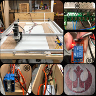
Next, I worked on automating the spindle. When I first received the spindle I noticed that there was a small jumper wire on the power supply that is simply labeled on/off. I was too interested in trying everything out to take the time to get it integrated with the GCODE. At that point i didn’t even really know whether or not this idea would even work. Now that I feel sufficiently comfortable with everything working I finally made time for the 30 minutes it took me to do it. I started with confirming that opening the jumper wire would turn the motor off regardless of the speed governor. It acted just as it was supposed to.
After this I added a relay module and connected it to the MKS 1.4 controller board. I controlled it in the same way that I’m controlling the lights and the fans in the laser controller. I am toggling the pin from the GCODE via the M42 command and am using pin 49. I still think its weird and worth noting that the S reference is still 0-255 not false/true, 0/1. So M42 P49 S255 turns the spinde on and M42 P49 S0 turns the spindle off. I just find it strange given that digital pin 49 is not a PWM pin on the Arduino Mega which is what the MKS 1.4 is built off of. The relay module is able to be set up for either normal open and normal close; I set it up such that the pin has to be actively engaged for the spindle to be on. This makes for a little bit safer of a set up. I tested this out by manually entering the commands into the Terminal of my OctoPrint server that is controlling the CNC machine. After this confirmation I easily added these two commands to the beginning script and the ending script within Simplify3D, which is what I’m using to create the GCODE for my CNC engravings.
After this was taken care of and tested, I built a simple box to put all of the controller boards in. There’s a surprising number of boards for the CNC machine. I didn’t spend too much time on dimensions. I just used the available space I had left on my board. I had a thin piece of plywood laying around that I used to build the box out of. It happened to be a piece that I used to experiment with when I was first testing the 5.5 W laser cutting through things. For reasons I never fully figured out I never got it to cut all the way through this plywood but it left me a pretty cool and pretty large Batman symbol that I left visible on the box for fun.
Another thing I thought to do was make an emergency switch for the two power supplies/rectifiers. This way if there is ever a problem I can flip the switch and have everything stop safely and easily. I did this a little different than typical though. I paralleled the AC wiring for the power supplies but I also paralleled another line that bypasses the switch and continues on for an outlet that powers the raspberry pi that hosts the OctoPrint server. I didn’t like the idea of just pulling the plug on the raspberry pi for fear of corrupting the SD card. I did all of the paralleling inside the box for the closest to code compliant that I was willing to do. Here’s a picture of the switch and a panoramic picture of all of the boards that are now inside the enclosure and finally not susceptible to dust contamination.
Here are some of the results of my initial experimentation. They may help future folks who try something similar.
Extruder Width:
I felt really dumb with one of the first things that I realized, but that’s how I learn best. Haha. In S3D there is a setting for “extruder” dimension, but then it also has a manual setting that overrides this setting. I had set the extruder to 2mm, but the manual entry portion still had 0.1mm from the process I had been using prior for my laser engraver. No wonder the CNC engravings were taking so dang long… It was making so many passes where one or two could’ve done a sufficient job. Whoops… A benefit of this though was that I learned that making multiple passes where one will do will greatly smooth the bottom surface. I still find it cleanest to use half the width so that the bottom of the engraving is well cleaned out and doesn’t overburden the motors.
Depth and Speed:
I’ve been experimenting with different woods. Pine really is a soft wood and oak really is a hard wood and should be treated accordingly. With pine I can do 0.5mm per layer pretty easily and on top of that I can do two layers before doing the “infill” which hogs out the inside of whatever I’m engraving. I was doing all of this at 600 mm/min, but I felt more comfortable at 500 mm/min. With oak, unless it’s a brand new bit I can’t use the same settings comfortably. I feel a lot safer with 0.3mm per layer and only a single layer before doing the infill. I’ve said it before and I’ll say it again I love being a turtle (anybody get that reference…) but in all seriousness, Simplify3D is awesome. The settings that can be manipulated are practically endless.
Bit:
So far I haven’t seen as definitive a decision as others have shown and posted about. My fluted bit seems to be working just as well as a straight bit, but I’ve been using mostly regular wood not plywood. I’m using just regular ol’ carbide bits. In general they’re working great, but they really only seem to be working well for about 10 hours or so before it’s getting a little too weak for the relatively underpowered stepper motors and spindle motor I’m using for the conversion. One of these days I might want to upgrade to geared stepper motors for stronger movement while dragging the bit through wood. Here’s what happened after 10ish hours of use:
I didn’t understand what was happening yet and did two basically back to back that resulted in the same issue.
This build is a consolidation of a few of my blog posts that can be found at my blog, Candler Customs. I really hope you like it and you learned something. Sorry for what is probably an abnormally long build section. Happy makin' y'all. -Paul
Candler Customs - Custom CNC Machine
Build in 'Cartesian Style CNC' published by CandlerCustoms, Jan 16, 2018.
Inexpensive Custom CNC Machine or swappable Laser Engraver utilizing OpenBuilds ACRO System
-
-
Build Author CandlerCustoms, Find all builds by CandlerCustoms
-
- Loading...
-
Build Details
- Build License:
-
- CC - Attribution NonCommercial - Share Alike - CC BY NC SA
Reason for this Build
I built this machine for learning, having fun, and sharing on my blog.
I also thought to enter this build as a way to compete in the "Ultimate Powerpack Contest". Fingers Crossed!! -
Parts list
Qty Part Name Part Link Comments 1 Acro System http://openbuildspartstore.com/openbuilds-acro-system/ Link Basis for System, I configured to 1000mm x 1500mm with Motors. 1 Z Axis Ball Screw https://www.banggood.com/100mm-Long-Stage-Actuator-1204-B... Link Adds Z axis to CNC Machine 1 5.5 Watt Laser (Optional Instead of Spindle) https://www.banggood.com/445nm-5_5W-5500mW-Blue-Laser-Mod... Link I change between the Laser attachment and the Spindle attachment. 2 Inductive End Stops https://www.banggood.com/SN04-N-5mm-Inductive-Proximity-S... Link End stops for homing. 1 MKS 1.4 Controller for Firmware Controller https://www.banggood.com/MKS-Gen-V1_4-3D-Printer-Control-... Link Utilizing a 3D printer controller for a Laser Engraver or CNC Machine 1 Raspberry Pi https://affiliate-program.amazon.com/home/productlinks/cu... Link Raspberry Pi for OctoPrint for remote control and viewing 1 Raspberry Pi Camera https://affiliate-program.amazon.com/home/productlinks/cu... Link Raspberry Pi Camera for Remote Viewing via OctoPrint 1 Extension Cable for Raspberry Pi Camera https://www.amazon.com/Adafruit-Flex-Cable-Raspberry-Came... Link Extra Long Cable to position camera as necessary. 1 Spindle with Power Supply https://www.banggood.com/ER11-Chuck-CNC-500W-Spindle-Moto... Link Spindle with Power Supply to utilize as Custom CNC Machine 1 Carbide Bits https://www.banggood.com/Drillpro-10pcs-0_8-3mm-Carbide-P... Link Assorted Carbide Bits 1 Relay Module https://www.banggood.com/5V-1-Channel-Level-Trigger-Optoc... Link Relay Module for Controlling the Spindle via the GCODE
![[IMG]](proxy.php?image=https%3A%2F%2Fi2.wp.com%2Fwww.candlercustoms.com%2Fwp-content%2Fuploads%2F2017%2F10%2FTerrifying-Laser-2-1.png%3Ffit%3D5118%252C2880&hash=239bd2cc913bafc4a51756aebc1cd732)
![[IMG]](https://i2.wp.com/www.candlercustoms.com/wp-content/uploads/2017/10/Monster-Laser-Engraver-Afar.jpg)
![[IMG]](https://i2.wp.com/www.candlercustoms.com/wp-content/uploads/2017/10/Monster-Laser-Close.jpg)
![[IMG]](https://i1.wp.com/www.candlercustoms.com/wp-content/uploads/2017/10/Monster-Laser-Cutter-Settings-2.jpg)
![[IMG]](https://i1.wp.com/www.candlercustoms.com/wp-content/uploads/2017/10/Monster-Laser-Cutter-Settings.jpg)
![[IMG]](https://i2.wp.com/www.candlercustoms.com/wp-content/uploads/2017/10/First-Cut-Through.jpg)
![[IMG]](https://i1.wp.com/www.candlercustoms.com/wp-content/uploads/2017/10/Terrifying-Laser.jpg)
![[IMG]](https://i1.wp.com/www.candlercustoms.com/wp-content/uploads/2017/10/Terrifying-Laser-2.png)
![[IMG]](proxy.php?image=https%3A%2F%2Fi1.wp.com%2Fwww.candlercustoms.com%2Fwp-content%2Fuploads%2F2017%2F12%2Ffullsizeoutput_3a2.jpeg%3Fresize%3D640%252C480&hash=ab6750f36f1747d2e5ef88867e03875b)
![[IMG]](proxy.php?image=https%3A%2F%2Fi1.wp.com%2Fwww.candlercustoms.com%2Fwp-content%2Fuploads%2F2018%2F01%2Ffullsizeoutput_442.jpeg%3Ffit%3D3333%252C2919&hash=3fb4735ca94e20870d305884830e2138)
![[IMG]](https://i0.wp.com/www.candlercustoms.com/wp-content/uploads/2018/01/fullsizeoutput_43f.jpeg)
![[IMG]](proxy.php?image=https%3A%2F%2Fi2.wp.com%2Fwww.candlercustoms.com%2Fwp-content%2Fuploads%2F2018%2F01%2F85uyEJdBQLiF97skC4Fy5w.jpg%3Ffit%3D640%252C480&hash=f12dff47d86e04df083fe7c8794e38d9)
![[IMG]](proxy.php?image=https%3A%2F%2Fi1.wp.com%2Fwww.candlercustoms.com%2Fwp-content%2Fuploads%2F2018%2F01%2Ffullsizeoutput_440.jpeg%3Ffit%3D640%252C727&hash=daf73b3a685439010e9359e3354cbfa5)
![[IMG]](proxy.php?image=https%3A%2F%2Fi1.wp.com%2Fwww.candlercustoms.com%2Fwp-content%2Fuploads%2F2018%2F01%2Ffullsizeoutput_442.jpeg%3Fresize%3D640%252C561&hash=ac2ff45be93b33dca6de9625f824c4fa)
![[IMG]](proxy.php?image=https%3A%2F%2Fi2.wp.com%2Fwww.candlercustoms.com%2Fwp-content%2Fuploads%2F2018%2F01%2Ffullsizeoutput_441.jpeg%3Ffit%3D640%252C582&hash=98faebfafbe4b931a000b15491906221)
![[IMG]](proxy.php?image=https%3A%2F%2Fi0.wp.com%2Fwww.candlercustoms.com%2Fwp-content%2Fuploads%2F2018%2F01%2Ffullsizeoutput_443.jpeg%3Ffit%3D174%252C1024&hash=d2684da4974f3cc6e00cb7e8a6bd6c81)
![[IMG]](proxy.php?image=https%3A%2F%2Fi2.wp.com%2Fwww.candlercustoms.com%2Fwp-content%2Fuploads%2F2017%2F12%2FExtruder-Settings-Screenshot.png%3Fresize%3D640%252C569&hash=751a81441f627e8f2433ad71e7d22c2c)
![[IMG]](proxy.php?image=https%3A%2F%2Fi2.wp.com%2Fwww.candlercustoms.com%2Fwp-content%2Fuploads%2F2017%2F12%2Ffullsizeoutput_3e7.jpeg%3Fresize%3D640%252C853&hash=6497a13593184e6d7102ff8de144a232)