
My fascination with building a CNC router all started about a year and half ago when I bought a 3D printer kit off ebay. After assembly and learning/printing parts etc. on it I was looking for something more exacting to make parts with. 3D Printing is nice for printing random gadgets but for making parts which require tolerances within say a 1/4 millimeter or so the technology is just not there. At the start of this year I started researching and reading all I could about CNC and ran across "Openbuilds" website and got hooked. I have a mechanical background with some electrical/electronics so I love this sort of stuff. Plus I'm a kind of CAD nut and do lots of 3D modeling (mostly Autodesk Inventor, learning Fusion 360 due to the CAM integration) in my spare time. I was completely new to CNC so it's been quite a ride learning all this stuff.
At any rate started buying parts around the end of January and started the assembly process around mid February. I made the initial gantry side plates at work where I have access to a milling machine, lathe, and other shop equipment. The 8mm Acme rods are slightly undersized at around 7.75mm so I quickly discovered the 16mm X 8mm bearings were a slopply fit and weren't going to work. Ended up making some plain bearings (bushings) out of Delrin plastic we have at work. I could machine the exact fit I needed and the Delrin will hold up for hundreds of hours so quite please with how they turned out. Not sure how others are handling this issue but this has worked great for me.
Most of the plates are variants of the standard plate design with tweaking to meet my design criteria and have been made from either 1/4" or 1/2" Acrylic (Plexiglass) or 3D printed plastic. There are still a few 3D printed parts still in use on the machine, hence I describe it as a prototype. Ideally you would want to make all the plates out of 1/4" and 1/2" Aluminum. I wanted to contain cost during the intial build to make sure my plan would all come together and work out before dumping a bunch of money up front on custom made plates. Initially on the controller side I started out with Synthethos gShield v5 / Arduino and some light duty Nema 17 Stepper Motors but was having intermittent weird problems, especailly with Z-Axis. Pretty much not knowing what I was doing up front as far as the power I would need to run this big of machine. I finally upgraded to the TingG and larger Nema 23 Sepper Motors and more powerful laptop computer.
On heavier and tough cuts of say 1/2" plexiglass I was getting a lot of flex on the Z axis carriage so I made a design change and added a couple 8mm linear rods and bearings to the carriage back plate. If you look at the photos I uploaded you will be able to see this mod. This has made quite a difference in the rigidity of it. Another small tweak I made was to use quite a few 5mm tapped holes on various plates. This makes assembly of the v-slot wheels and spacers a little faster and easier as you don't have to worry about a nut on the back side. Openbuilds store was out of the eccentric spacers when I placed my first parts order so my main gantry side plates do not have these incorporated. I found if your holes are precisely spaced and drilled (for 5mm, you need 7.1mm if using the eccentric spacers) you can get by without them. My gantry carriages fit nice and snug to the C-Beams, quite pleased!
I plan on installing some proxy type limit switches in the future. I will have to upgrade my current Drag Link Chain size. I was kind winging it when I bought the first ones off ebay, which are to small to house the wiring needed for the limit switch upgrade. Other than that I'm pretty much done with the project. Heck, the Acrylic plates are holding up well and seem strong enough as most of the pressure is exerted on the C-Beams and V-Wheels.
I'll probably host all my modeling files over at "GrabCad" where I am a member. I'll provide a link where you can download the model files. I'll try to convert most of the Inventor files to .STEP type. I haven't used SketchUp so not sure if it can import STEP type.
07/05/2016
Uploaded some renders of the build.
Added videos of my baby. See the "Files and Drawing" tab to download and watch!
Uploaded a .STEP file of the complete Assembly. See the "Files and Drawing" tab. Filename: OXRouter C-Beam 1KX1K.stp
Autodesk Fusion 360 can export files to SketchUp so folks wanting files in SketchUp I will be able to provide.
07/14/2016
Uploaded some SketchUp files of the various plates I used for the build.
See the "Files and Drawing" tab.
07/15/2016
I wanted to elaborate a little on the accuracy I'm obtaining with the C-Beam. One of the primary reasons I went the Acme rod route was I felt it would be the most precise for a budget machine. A week or so ago I ran some test. Over a 28" (max) distance on the "Y Axis" it consistently held +-.050" (1.27mm). The method I used was to mount my Bosch DLR130 (electronic measurer) on a tripod. I would then shoot the start and stop distances. Repeated this about 5 times with the same result so I was pretty happy. On short distances of say 4 -6 in. virtually spot on. Had to do a minor tweak in the controller settings. A little trial and error, but not to terribly hard to figure out. The TinyG has pretty good documentation on Git Hub.
The "X" axis was similar, maybe a little less accurate, the Acme rod is not machined as good as the 2ea. "Y Axis" rods and has some wobble to it. Not real happy with it, haven't check with the Open Builds web store on an exchange but they might work with me on it. On small circles I'm getting a very slight egg shape being caused by the "X axis", not really noticeable on larger holes. Overall accuracy is amazing for a hobby machine.
I'd be curious how the belt systems compare, as far as accuracy, over these distances. Comments welcome under the Discussions tab.
Hope you enjoy the build!
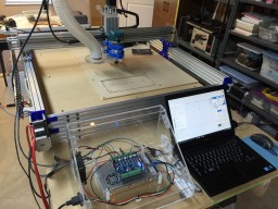
C-Beam Prototype
Build in 'Cartesian Style CNC' published by Rwetzler, Jul 15, 2016.
This is a variant of a typical OX (Mark Carew inspiration) router using C-Beams/8mm Acme rods to drive all three axis. I went with a 1000mm x 1000mm frame size. Useable space is 28" (711mm) X 26" (660mm) with a Z axis work travel of approx. 3.25" (82.5mm). A TinyG is used as a controller along with Fusion 360/Chilipper as the software for generating and running gcode files.
-
-
Build Author Rwetzler, Find all builds by Rwetzler
-
- Loading...
-
Build Details
- Build License:
-
- CC - Attribution - CC BY
Reason for this Build
Hobby, Parts Making, Fascination with CNCInspired by
Mark Carew, Open Build Community -
Attached Files:
-


