
Hello OpenBuilders!
I wanted to get this started on here and talk a little bit about my experience putting this together so far. I will preface this with saying that although I purchased this for myself I have it set up at my work, which is a research lab. Part of this lab is a full machine shop, so I may have access to tools that others do not. This shouldn't make you think that anything I am doing couldn't be done in a garage or basement (or wherever else your significant other allows you to build haha)
First off, I want to say that I was immediately impressed with the finish on all the anodized parts. The C-Beam elements were perfectly sized and the finish is great. I am used to using 80/20 and the difference is stark. My first purchase from OpenBuilds was the v-slot belt operated linear motion element (cant remember the name at the moment) and the finish was the black anodized, so I didn't have the aluminum finish to compare before. Also in this section has to go the packaging. I buy a lot of stuff on Ebay or websites to feed my work/hobby habit of building, and have been underwhelmed in the past by other vendors in the care of packaging. OpenBuilds sends this like they are sending Faberge eggs. I realize that some people don't care about the shipping as long as it arrives safe, but to me it shows they care about their product and by extension my build. so +1 to the OpenBuilds team for that.
When I measured the v-slot elements initially i noted that the 500mm 20X60 was 8mm beyond nominal (508mm) on both, and the 1000mm's were 10mm beyond nominal (1010mm) based on the fact that these were both the same size I assume these overages were to compensate for machine variability and ensure no part was undersized. I don't know if you would get a different size or if they would be the same but assume that you have at least 4 cuts beyond the 20x40 listed in the directions. I have the luxury of a huge Johnson saw (large automatic band saw) and a large disc sander so cutting and squaring wasn't that bad, but it did add at least an hour onto the build.
I have also identified a few places where some additional bracing will benefit the rigidity, which will come into play for my first upgrade (note: I have barely put this thing together and don't have it all square yet, and already I have several modifications planned. I have a problem...). When I get the chance I will make up a SolidWorks model of my mods and post them on here or on a new build. If you have any questions on the build feel free to ask. I'm no expert but am willing to help however I can.
I will update this as I add the electronics (Smoothie Board and 4 ea of the drivers in the part store.
Overall very pleased with the bundle and looking forward to my first cut!
EDIT: Another thing I forgot to mention was that the set screw which secure the lead screw collars in place on the Y and X axis' needed to be shaved down a little bit to stop them from interfering with the
vslot/cbeam they were mounted on.
-PhotoSgt85
UPDATE 1/19/2017:
So I haven't had a drop of time to spend on this since the inital post due to another project here at work. (Which I will try and get permission to make openSource)
Today I ordered some more V-Slot to convert the bed of the machine from MDF to aluminum as I will be working in making aluminum plates almost exclusively. I am worried using cutting oil would deform the MDF too readily and my turnover in spoiler boards and mounted beds would be too much. I am using metalguru's design as a starting point and then making some modifications to increase rigidity in the bed. I'm sure I am not the first but I will be looking to make some clamping options for the V-slot as well as some jigging devices to make repeated cuts straight forward.
About to jump back into the setup...
As always thank you for being such an awesome community!
-PhotoSgt85
UPDATE 1/26/2017
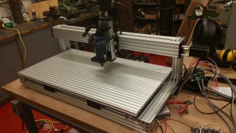
Work on the C-Beam Machine XL is getting really close to being finished! I had first movements of the X axis today and will be finishing up tomorrow on the other axes.
I was having a hard time getting the DQ542MA drivers to work in the common cathode configuration, but luckily for me I work with a few great electrical engineers, and one in particular helped me solve the problem. I am using a 5VDC Mean Well power supply for the signal portion of the switching going to the SmoothieBoard (which is set in an open drain configuration running in Variant C). Turns out that all I needed to do was use a resistor to limit current as I was experiencing an over current situation when I supplied the drivers with 5V from the board or power supply.
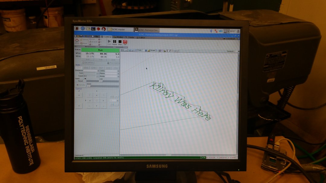
When I get it all nailed down I am going to produce a fritzing diagram of the setup so that others can learn from what I've done. As you may have been able to tell from the photo I have bCNC running on a Raspberry Pi 3 which is currently interfacing over USB. Final setup will hopefully have an Ethernet switch so that I can access the pi from my office.
If there is any makers out there who have experience with the Raspberry Pi 7" touch screen I would love to hear about it.
I hope to post more photos when the bed is completed and when movements are up and running I will post up some video. Looking forward to making this machine productive so that I can get on to my next couple builds, which should be designed fairly soon. I will be posting my design for a new Delta style 3D printer for the lab as soon as I get permission to post the designs.
-PhotoSgt85
UPDATE 1/27/2017:


Well, managed to get the Y axis mounted before the end of the day and aside from having to align one of the actuators it is now in an operable condition. I have to get another V-Slot piece for the center (and more t nuts and screws as I neglected to get enough. I am also going to have to get some more brackets for the extrusions on the ends of the bed as they currently are only held on by two t nuts.
For construction I had to reverse the direction of the 60mm (i think that's the length) screws in the C Beam Plates and feed them into T nuts on the bed. Doing this meant that I had to use an even number of t slots (6), and since 500mm/20mm is 25, the plate had to be placed 10mm off center. I plan on cutting new plates that rectify this issue or make the Y axis 1000mm.
All that's left now is to bolt these to the frame and add my spoiler board. Since I have some MDF itll probably start as that, eventually though I hope to transition to HDPE, which I can recycle into new spoiler boards. Hope this is helping someone out there.
On the documentation end I am trying to find a fritzing file for the smoothieboard but havent found one yet. Once I find one I can make up the wiring diagram. I'm using some terminal boards as power buses and signal buses for the dual Y axes. Once we have movement and cutting I will get some video and post it here.
-PhotoSgt85
UPDATE 1/30/2017:
Today was finally the day that the C Beam Machine XL was completed! I have to say that I have say that it has come out quite nice, and although I have some tweaking to do as well as electronics management I am looking forward to now pushing forward with some cuts and fine tuning the machine. I am sure that I will have more to go for this to be the everyday machine I need it be but for now I am looking forward to first cuts and pushing some plates forward so that I can get a move on some other designs that were waiting for this to be completed. I have to say that although the bed has been interesting after seeing it in person I can say that I would go with anything but the V-Slot. I already was able to hold a spoiler board in place for some testing just by restricting two opposing corners with some screws in T nuts. This machine should be humming along soon on my next build, as well as some upgrades that I feel the XL will need. Now to come up with a name for it....

-PhotoSgt85
UPDATE 2.7.2017:
Well, its been about a week since I called this build done and even though it has been in working order I never go the chance to cut anything as I was working on fabrication of the Desktop PCB Mill and my Delta 3D printer from scrap 80/20.
So today I finally figured out Fusion 360 enough to get myself in trouble, and by that I mean I am able to output G-Code that bCNC can read and the smoothieboard likes. After some initial snags with having my drivers set wrong (3200 instead of 1600) I finally got a good cut. Since I had the MDF laying around (was originally going to be the bed I decided that it was a good material to test cut.

This test cut is of the base plate of the Delta 3D printer joint :

I am not sure how well you can see it but the holes and plate are all to tolerance. Not bad at all. Tomorrow I will be beginning on cutting aluminum and then working on cutting these plates, as well as the NEMA 23 mounts as well. I may just throw some OX plates in there as well......hmmmm.
Other than that I am including some videos before I got the micro stepping figured out. Also be on the look out for the PCB mill bed plate to be cut as well as some experimental setups I have in mind. (Have to do work too, right?) Enjoy, Comment, and build!:
-PhotoSgt85
UPDATE 2.8.2017:
So I guess this will be daily updates while I dial the machine in and work on the cuts for the Delta printer plates. I tried a facing operation on some stock we had lying around and I noticed that my Z axis was out of square with my build surface. I ended up taking the whole axis off to tighten everything as my anti-backlash nut screws were loose (must not have tightened them enough when I build the machine). I did notice some ridges as I run my finger across the path of the cut, but mostly in one direction, which to me means the end mill isnt square to the work surface. Hopefully my reassembly solved this...Guess Ill find out tomorrow. Anyway, here is some pictures of the part post cuts. There are several different runs that I stopped at different times, which explains the varied finishes.


Hopefully tomorrow will bring me more luck with this trial cut.
-PhotoSgt85
UPDATE 2.9.2017:
So I had my first successful part cut on the XL today.

You probably notice that the slot looks rough, the face is swirly and not even completely cleaned off, and the edges have no consistency in their fillets. All of this is my fault, and not the machine. First the 1/4" plate I used was barely large enough to get this part out of it as it was a scrap piece laying around our lab. The funny part is its probably from the 1950's, so the metal has had some time to collect nastiness. My attempt to clean up the face on the disk sander was only moderately successful, as the part is almost as large as the disk itself. Safety third on that one...
I had to break the edges as I had a few people I was handing this around to and didn't want anyone hurt on the edges, where were quite sharp.
Finally the slot (and although you can't tell the holes as well). When I was making the g code in Fusion I had the stock set to exactly .25", which meant that my spoiler board's variance made for material left after the final cut. In order to clean this up I had to use a Dremel, and well that thing just ate through some of the slot walls, so yeah. I drilled out the rest of the holes with the appropriate bit and viola, workable part. This was supposed to be a test part so the fact that it is serviceable for my needs is excellent. Tomorrow I have to finalize the Delta Printer design and then I can get to laying out the cuts for those parts, which will probably take about 7 hours or so. Not much else for today as we had a shorter day than normal given the 10" of snow we got. Have fun and happy building!
-PhotoSgt85
C-Beam Machine XL
Build in 'Cartesian Style CNC' published by PhotoSgt85, Feb 9, 2017.
Overview of my experience building the C-Beam Machine XL from OpenBuilds, along with updates as I move along and get it going. My application is for creating plates needed for lab functions, 19 rack bay covers, and whatever else arises.
-
-
Build Author PhotoSgt85, Find all builds by PhotoSgt85
-
- Loading...
-
Build Details
- Build License:
-
- CC - Attribution - CC BY
Reason for this Build
Why not? I need the capabilities at work and for other follow on machines.Inspired by
OpenBuilds and the makers of the C-Beam Machine and C-Beam Machine XL -
Attached Files:
-


