
Hi Guys:
This is my latest build. I decided I'd like to beef up the standard OX build a bit, stiffen up the X and Z axes, and generally step it up a notch. Thus was born the Ox HD.
I wanted to use a double 20x80 beam setup for the X axis, and a C-beam Z axis. This should stiffen up the moving parts admirably. I also had a few ideas about strengthening the base and generally making things a bit beefier.
I got together via email with Chris Laidlaw and cooked up some new plates, at least new to me. Turns out he's pretty much done it all before. He says he's sold quite a few sets similar to this, but I couldn't find any builds on the OB site with similar design, thus I thought I'd publish one mine own self.
He already had a set of X axis plates designed to use 20x80 for the Z axis instead of the standard 20x60. Turns out this also works perfectly for using C-beam as the Z axis instead of the usual 20x60 and the flimsy 1/8" motor plates with the lead screw setup. He normally supplies these with the spacer blocks, but with the C-beam they are not necessary. The plates are also 20mm taller to accept the 20x80 X axis beams I had in mind as well, and they have an extra set of holes to run 8 wheels for the Z axis instead of the usual 6. These plates are available on his eBay page.
I also redesigned the side Y Axis gantry plates to accommodate the taller X axis beam, with a few more holes for mounting the beam and the corner brackets. The plates are 25mm taller than the standard Ox, I felt I didn't want to go the full 2" of the Tall Ox to preserve more stiffness. I also had him add a couple of extra holes for a 20x60 cross brace instead of the 20x40 that is on a stock Ox. In addition, he put in a relief cut to fit the current stepper motors that the OB store sells, to clear the large flange on the front of the motor, so they could be mounted without spacers. Also gives a couple of more mm of shaft stick-out to make mounting the pulley easier. These plates are also available on his eBay page. I think the plates cost about $50 more than the standard ox plates, for the whole set.
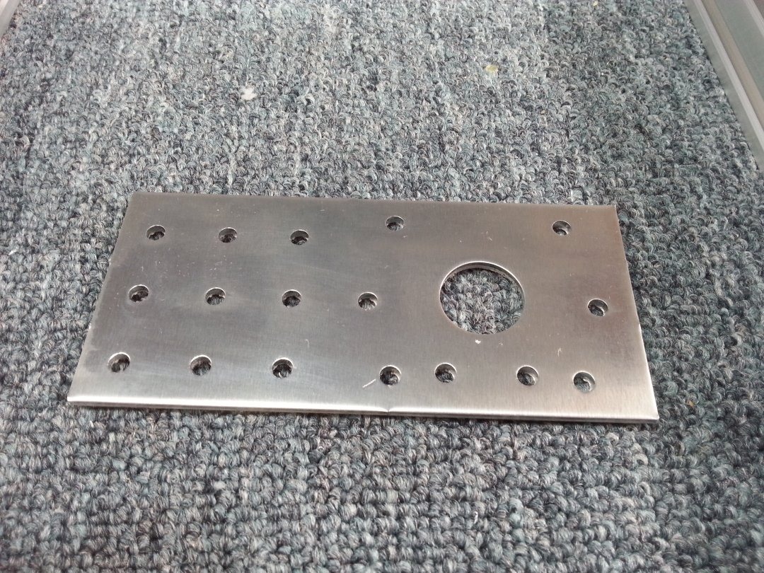
The Jewels he sent are shown below. Dang, that guy does nice work. Thanks Chris. By the way, he said the plates that he sent me, these plus a set of standard Ox plates, were plate sets number 500 and 501. May he go on to make another few thousand... I'm still waiting for my all expense paid trip to Hawaii for being #500.
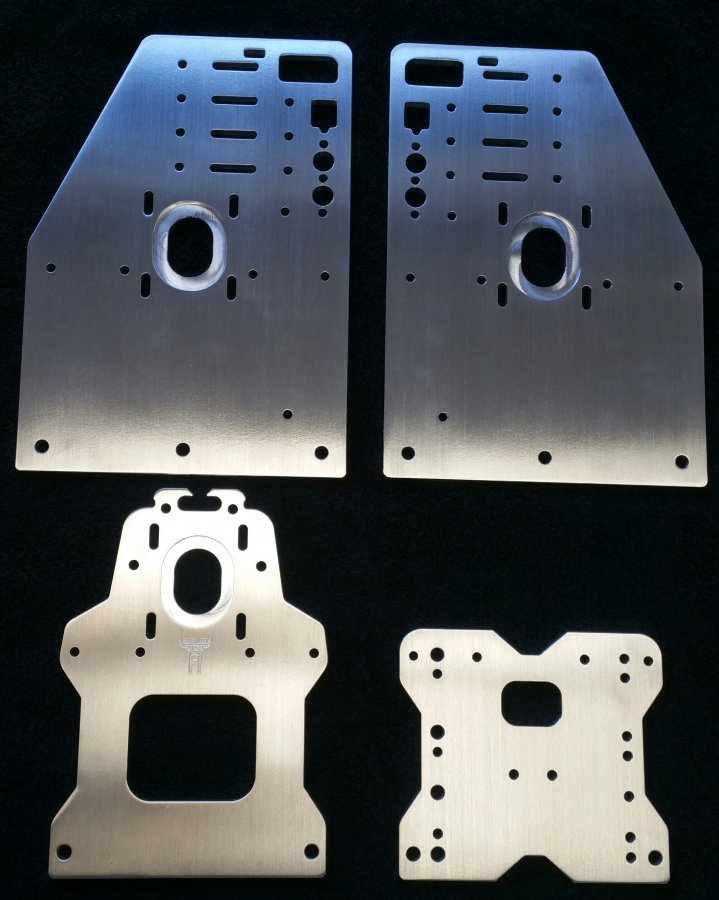
Once I had these babies in my hot little hand, work could begin.
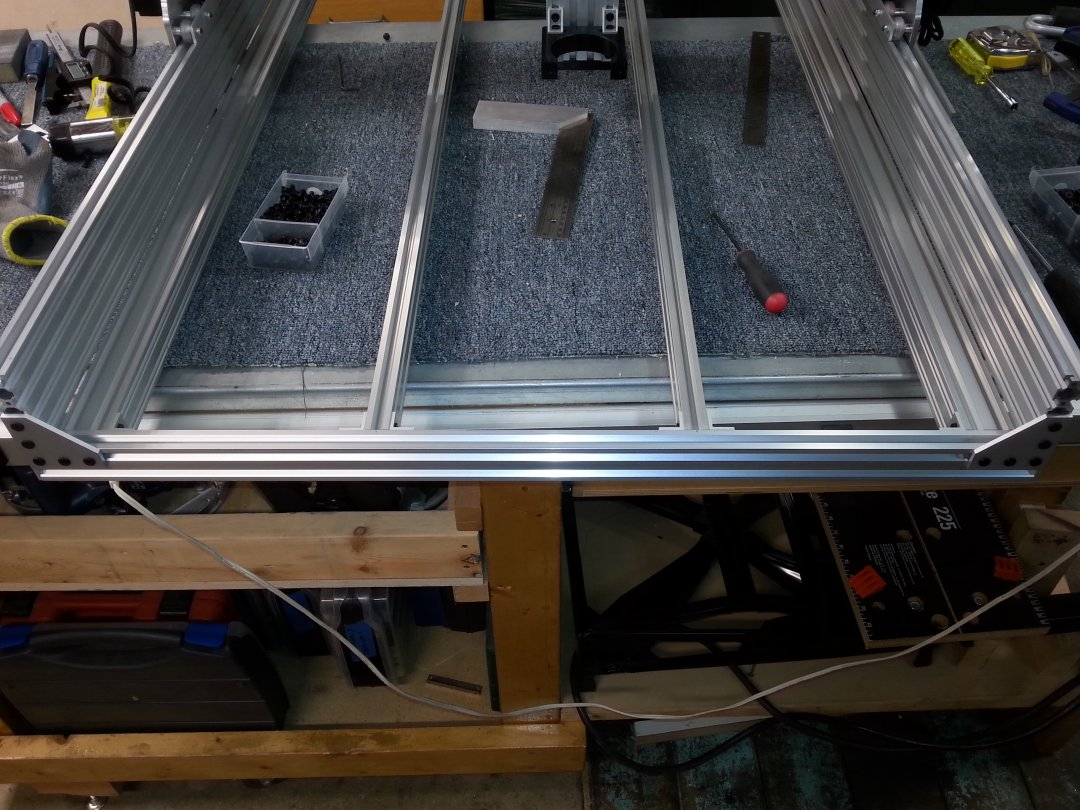
I started by cutting the X axis 20x80's and 20x60, and using my nifty little squaring jig to get them perfectly square and all exactly the same length. See A Slick way to Square up V-slot and C-Beam. I made all of these 800mm long, so the final machine will be 800 x 1000mm. This is so I can get a full 24" x 32" machining area on the bed in order to fit standard kitchen cabinet sides and doors.
I then glued the two 20x80's together using a few strips of 3M VHB foam tape, type 4926. This stuff is really sticky, bonds aluminum almost as well as epoxy, and is about .015" or just a bit over 1/3mm thick. I used 1/4" strips on the top and bottom, and a 1/2" strip down the center rail, along with a few 4" strips on the other two rails. For all practical purposes, this is now a single piece of extrusion, instead of 2. Makes things much stiffer, and is way less work than drilling and tapping the rails for bolts. The tape is not real cheap at about $10 a 5 yd roll, but considering the price of screws and especially labor to drill and tap holes, it works out much less.
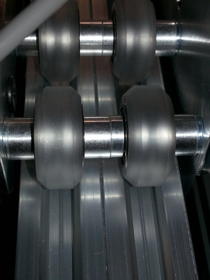
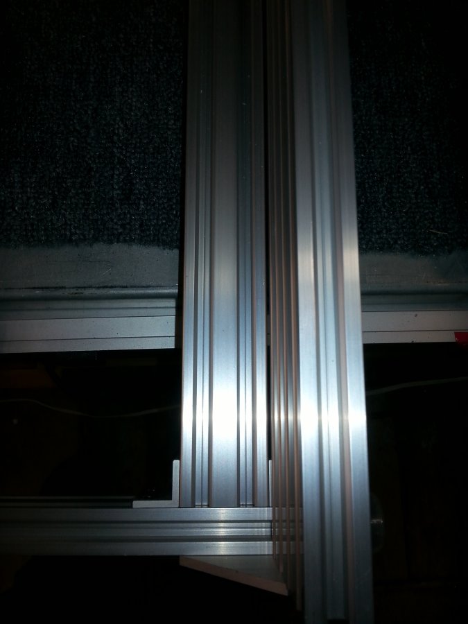
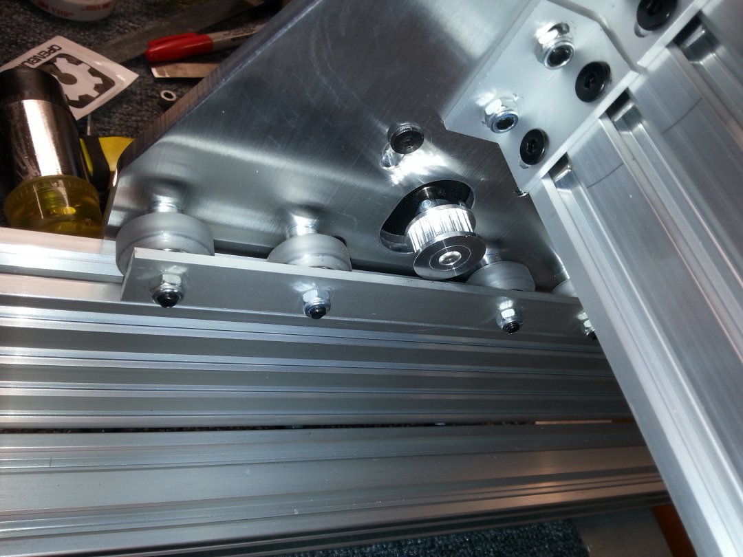
Just a note, since the tape is about 1/3 of a mm thick, it spaces the rails a bit further apart. This could result in binding if you use the standard 9mm wheel spacing for the X axis carriage. So, instead of using a 9mm spacer between all the wheels as I normally do, I used a 1/4"(6.35mm) and a 3mm spacer. This gave exactly the right extra clearance to compensate for the thickness of the tape. Although you can't tell, this is shown in the photo below. Take my word for it... 0.35mm is really hard to distinguish by eye...
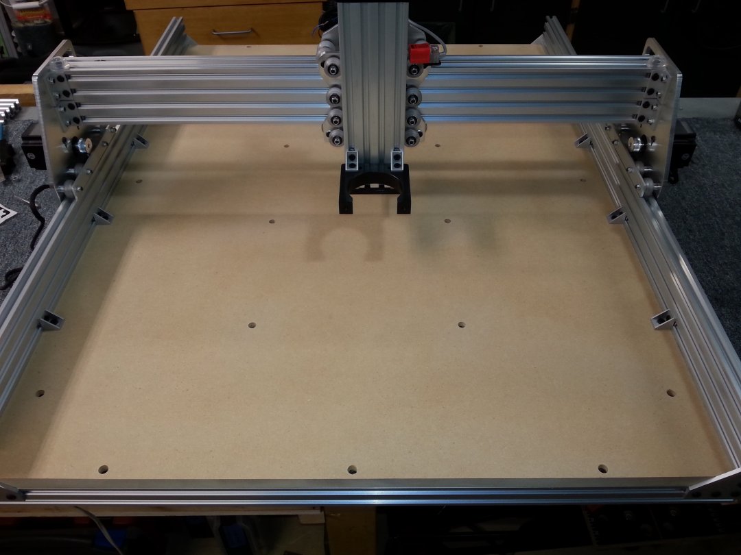
I'm getting a bit ahead of myself here...it was time to move onto the Y gantries. I usually assemble the Y gantry plates first, putting on the motors and all the wheels and use a scrap piece of 20x80 to preset the eccentrics in approximate position.
Then I assemble the X axis plates and wheels, (don't forget the nut block) assemble the Z axis, then assemble the gantry into a unit. It's way easier to slide the whole X/Z axis assembly onto the rail than it is to try and assemble it around the rail.
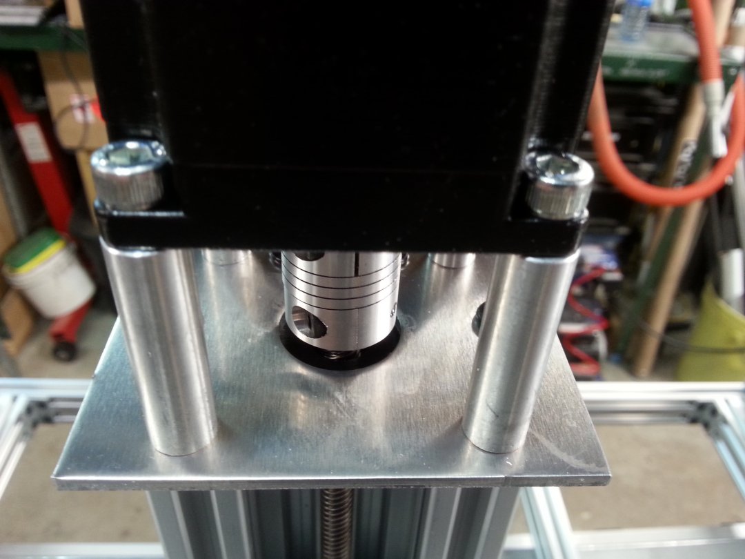
Oh, one note, when mounting the nut block on the front X axis plate, be sure to use 4mm of shims under the block. That is the required spacing to center the lead screw on the hole in the nut block for the C-beam actuator. I used a 3mm and a 1mm. The rest of the C-beam actuator is pretty much stock, except there is no internal gantry plate on it. Don't forget to file flats on the lead screw for all the setscrews on the lock collars and the flex coupling.
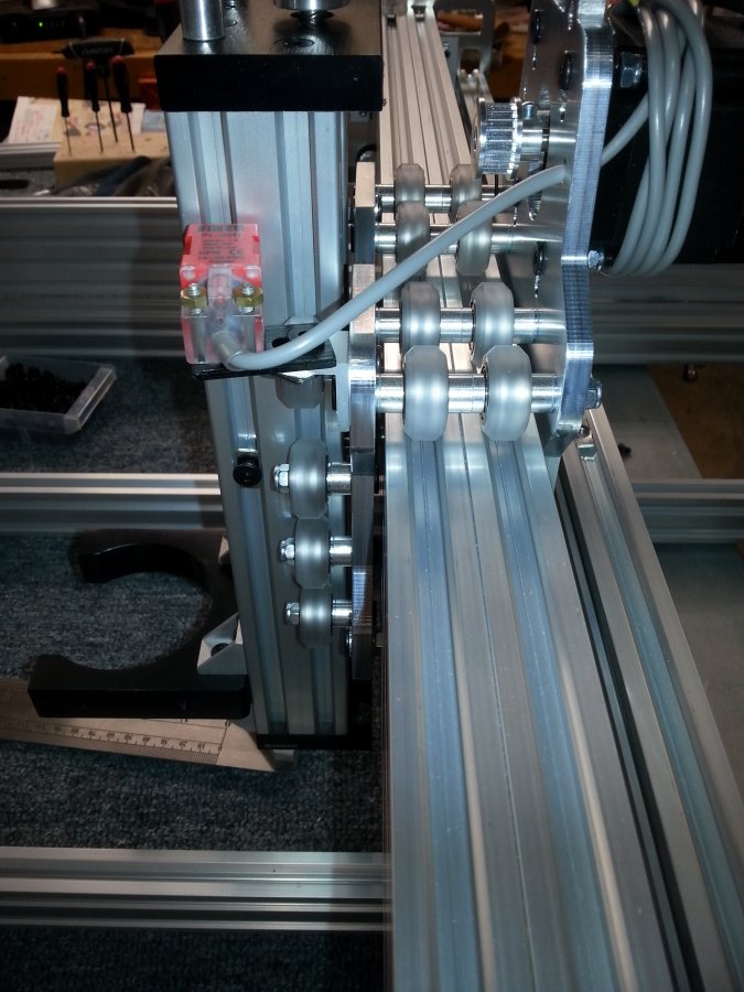
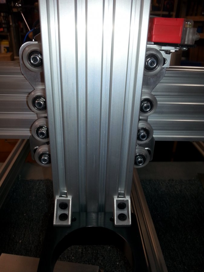
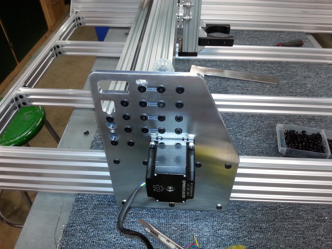
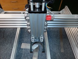
I assemble one end of the Y gantry plates onto the X axis rails and the brace, and install the X/Z axis onto the rails before buttoning up the other Y axis plate. Just don't forget all the t nuts you are going to need on all the cross members before bolting it together. In this build, I added another hole on the Y gantry plates for another corner block on the front of the X axis beam, and 2 more holes on the back. I decided to use 2 x 4 hole corner brackets rather than cast corner blocks on the front side, and 6 hole corner brackets on the back, but you can use either. The next 2 photos show the X axis carriage and the Z axis mounted on it.
At this point, I can temporarily slide the 1000mm 20x80 rails into the Y gantry plates and check everything for square. With the rails inserted, and the gantry sitting on the bench, I measure the width of the rails at both ends. It should be exactly the same. Make sure your eccentrics are snugged up and all the screws on the y axis plates are tight. If something is out of square, it's easier to correct at this point. I am able to measure the final width from outside to outside of the Y axis v-slot, in order to get the width of the two end 20x40 rails for the base. The Longitudinal rails are just 40mm shorter than the 20x80 side rails, in this case 960 mm.
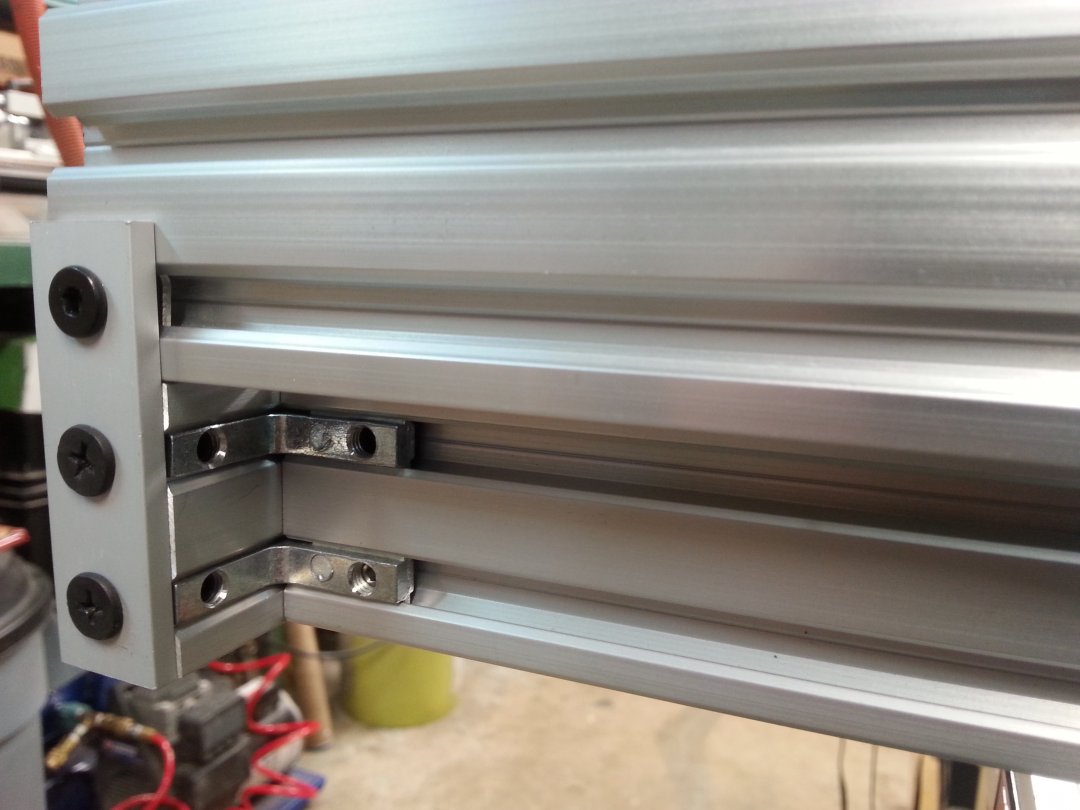
Next step was to assemble the base frame. I usually use 6 pieces of 20x40mm for the base of the router, along with the 2 20x80 side rails. Since I have the measurements from the mock up above, I can go ahead and cut all the pieces. There are pieces across the front and back, and 4 longitudinal pieces under the bed to support the spoil board. One of my signature tricks is to put cast corner brackets on top of the bed which are bolted into the 20x80 side rails, and then through the spoil board into the outside 20x40. This stiffens the side rails immensely and prevents them from deflecting sideways, something that the original OX design does not do. I do this on all my standard OX builds. With the HD, I wanted to beef this up even further, so I used 40x40mm for the two outside rails that tie into the 20x80's. This should add another level of stiffness to the bed. I would have used all 40x40 for the bed rails, but I didn't have enough in stock. As always, the spoil board will be bolted every 200mm to all the bed support rails using screws recessed into the table into t-nuts on top of all the rails. And yes, this is a major pain in the butt to align all those dang tee nuts and holes.
Oh, and as you can see, I use 4 hole corner brackets on each side of the rails to hold them in place. The outside base rails are spaced in 1mm or so from the inside of the 20x80 side rails, to prevent the lower wheel nuts from scraping on the outside of the base rail as it travels down the 20x80. The slots on the cast corner brackets easily absorb this extra mm when bolting down the spoil board. If you look closely, you can see the gap between the 20x80's and the 40x40's.
One important thing is to make sure the base is square and the same width and length on both sides. The easy way to check for square is to put a measuring tape corner to corner. Hook the tape right in the center of the hook on the corner of the extrusion, and stretch it to the other corner. note the measurement. Now do the same across the opposite corners. The measurement will be exactly the same if the frame is perfectly square. You can whack the corner of the longest side with a rubber hammer to adjust it until it is perfectly square. Note that your side rails and end rails must be exactly the same length to begin with or this won't work. Recheck corner to corner on the 20x80 V-slot Y axis rails after they are assembled on the base to make sure everything is still square.
Can anyone see my screw up here? I forgot to put the tee nuts in the base rails that are used to bolt down the spoil board. <Sigh> Ah well, now I have to take out 16 screws and try to slip them in... I also forgot the tee nuts on the side rails as well. They are not quite so much of a pain to put in.
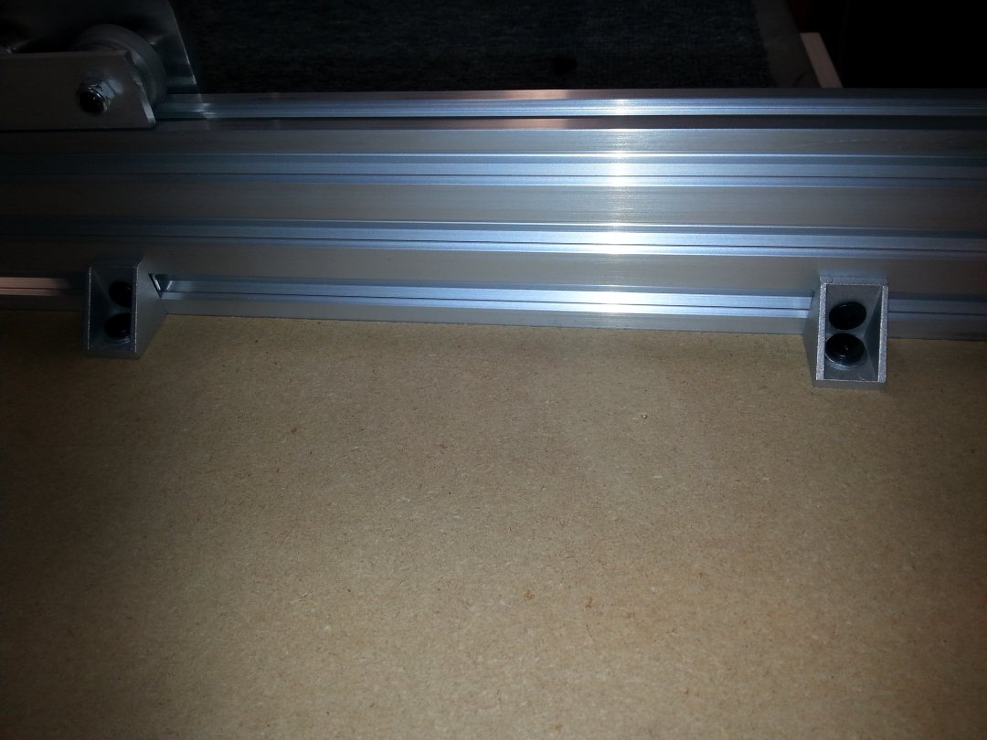
As you can see, there are a lot of screws in this dang thing... Also note the urethane foot (on top of the rail in the foreground) that I use for a soft bump stop for the X axis (and the Y as well)
And, I also added a stiffener plate to the upper Y axis wheels. I kind of like the Ooznest Ox with its inner plate that joins all the wheels, but this means leaving a gap between the spoil board and the 20x80 rails for the stiffener plate to move in. Since I think the addition of the tie ins between the 20x80 rails and the base/spoil board that I do has much more affect on the stability of the side rails, I went with a much simpler tie bar holding all the upper wheels together. It's a simple 3/4" x 1/8" flat aluminum bar with holes drilled for the wheel screws. I added a 1mm shim between the wheel and the stiffener so the wheels don't rub. I figure this will stiffen things up nicely while still allowing me to strengthen the side rails by tying them to the base.
So, got the spoil board made, drilled, and installed this afternoon. I must be getting good at this, because it fit like a glove first try. I mark all the hole locations on the spoil board, and drill any that need to be recessed with a 1/2" Forstner bit down to about 5-6mm depth. Then I drill these and all the rest of the holes with a 6mm bit through. This gives a bit of wiggle room to line up the screws and Tee nuts underneath. I then use a countersink from the bottom to clean up any blowout from the drill. I mark the positions of the tee nuts on the bottom frame with a pencil, and line them all up just before I lay down the bed. A magnetized screwdriver and an awl allow me to fine tune the position of the tee nuts through the hole just before I put in the screw.
Here's a detail on the side 40x80 support. The 30mm screws go down through the spoil board into tee nuts on the 40x40 under the bed. The rest of the screws on the bed are countersunk 15mm's.
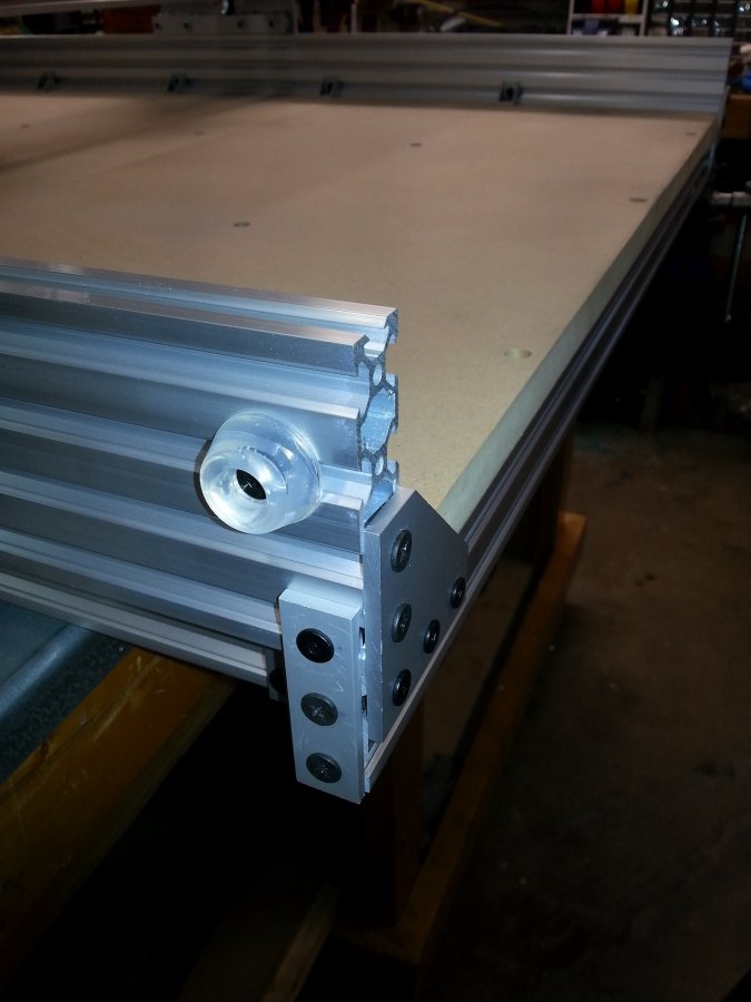
And a detail shot of the corner of the bed with the bump stop.... Note that I used a 3 hole joiner strip to cover the ends of the front and back rail, and attach it to the Y axis v-rail. This is why it is important to get the width of these rails exactly right, to avoid putting stress on the side 20x80 v-rails. I still need to put a couple of end caps over the top 2 sections of the 20x80. If you've ever ripped the crap out of your arm or hand by grazing the sharp cut edge of a v-slot, you'll not regret spending a few dollars on these.
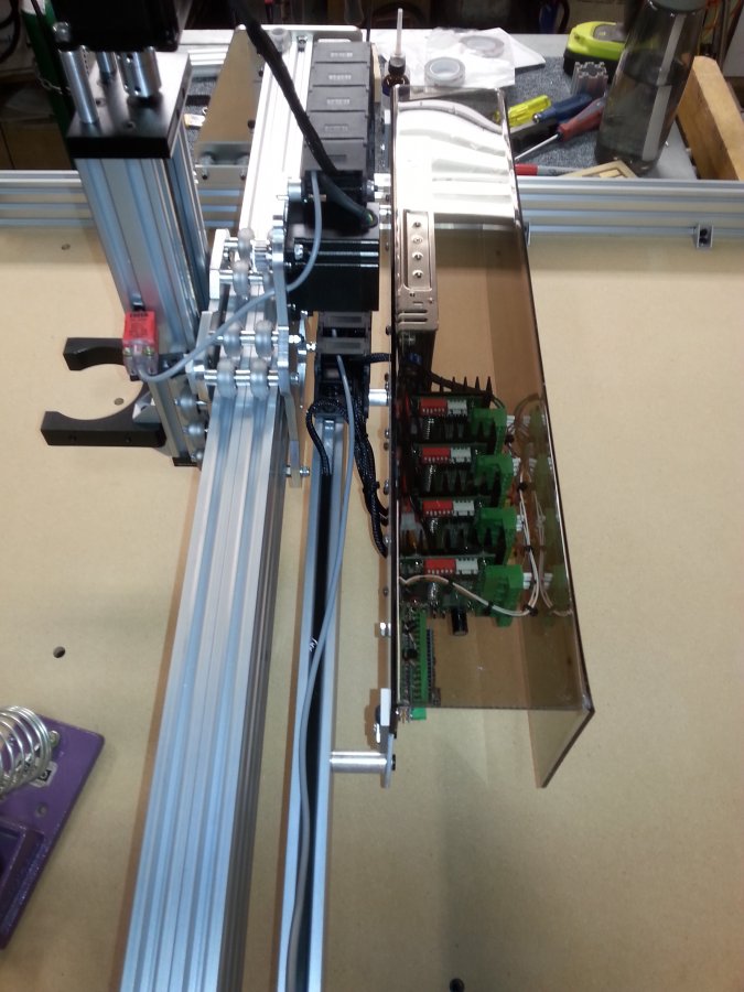
So, got the electronics pretty much done and dusted today. Mounted the arduino, stepper drivers, and power supply onto the mounting plate, wired it all up, and mounted it on the rear of the gantry. All the motors are wired up as well. This is pretty much the same electronics package I use on all my builds. The plate has mounting holes for all the devices, as well as holes spaced at 20mm in the center and at both ends for mounting onto V-slot. I mount it using some 30mm aluminum spacers I get from McMaster Carr, which are quite a bit larger than the ones OB sells. This keeps it out of the way of the X carriage motor. I also mount a u-shaped acrylic dust cover to keep junk out of the electronics, but it has lots of room underneath for air circulation to keep the electronics cool.
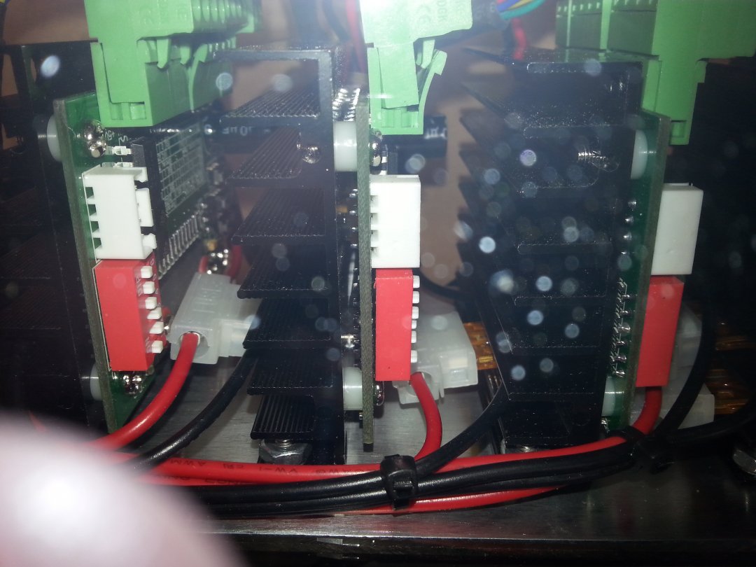
I use SainSmart TB6560 stepper drivers which are pretty reliable. The switch settings legend on them is incorrect, however, and it took me a while to figure out how to get them to work properly. They are wired through 5A fuses individually to the power supply outputs.
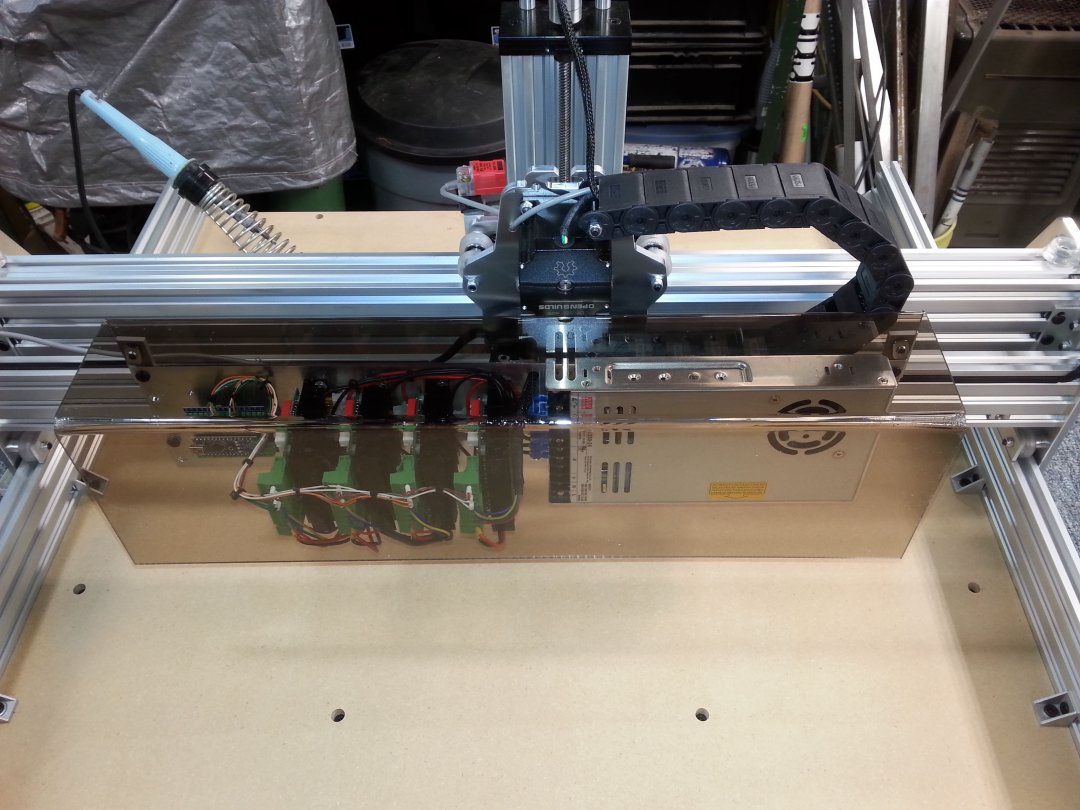
This is a side view showing the mounting plate, standoffs, and cable chain.
Here is a detail shot of the wiring for the stepper drivers. You can see the automotive style fuse holders tucked in between the heat sinks.
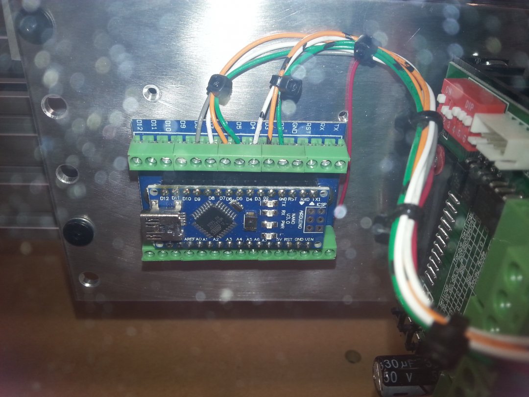
And here is a shot of the Arduino Nano that runs the whole thing. These two shots are a bit fuzzy because they were taken through the Plexiglas shield.
That's it for now. All I have left to do is wire up the Homing Switches, and I can try to let some of the magic smoke out! I will post a bit more when I get the electronics tested.
LAST UPDATE
Throw the switch, Igor! It's ALIIIIIIIIVVVVVVVE!!!
Fired it up today, homed it first try. Works like a charm, after a bit of tuning on the stepper drivers and the GRBL settings. Another build bites the dust. I have a feeling I'm going to make quite a few of these...
I also added the Sketchup model in the files section, I guess the file was too large, I kept getting an error when trying to upload it. So, I zipped it and that worked. Enjoy!
MG
UPDATE:
I have mad a couple of enhancements after building several of these routers. First, I replaced the 4 hole angle brackets in the outside corners of the base with the OB store hidden corner brackets. This gives me another 40 or so mm of Y axis travel, because the original with the 4 hole bracket would hit the wheel nut and prevent the gantry from going right to the end. This is only done on the outside connection between the front and back base rails and the outside base longitudinal rails. Good application for these parts. I thought about using the Makerlink corner brackets but they are too long.
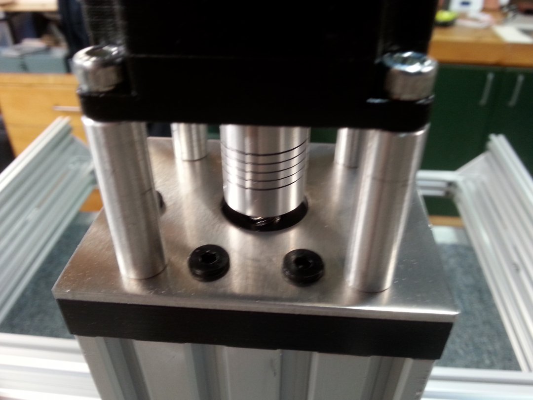
Next up is a modification to the C-Beam stepper motor mount. I have long hated the 2 screw motor mount for the c-beam, and decided to do something about it. I had some plates made up for another project to tie the end of a c-beam to a cross beam 20x60. The bracket duplicates the holes in the end of a c-beam, but adds 2 more motor mount holes, as well as 9 holes on 20mm centers to attach to a 20x60. A photo of the original plate is shown below:
The next two photos show the motor mounted on the end of the c-beam with the additional plate. Note that I cut the plate down to 80mm to match the width of the c-beam end plate by cutting off the 9 hole portion. Note that I also use heavier duty bolts with smaller heads, and the standard 35mm standoffs available from the OB store. The additional two mounts are held onto the plate with nylon lock nuts (not visible). This makes for a much sturdier motor mount.
Note that Chris Laidlaw has a wider version of the C-Beam end plate with 4 mounting holes available on his Chrisclub1 eBay page.
Keep Calm and Route on!
UPDATE II
I have abandoned the double 20x80 X axis beam in favor of a single piece of C-Beam. This eliminates gluing the two 20x80's together, and also eliminates the thicker spacer between the wheels. I usually put a piece of 20x40 into the open channel of the c-beam just to stiffen it up more. I drill about 5 pairs of holes for an M4 socket head screw through the 20x40 evenly spaced in the bottom of the v-slots, and put tee nuts in the v-slots of the c-beam. Then, I screw the 20x40 into the c-beam using M4x20mm socket head capscrews. This makes it pretty strong. Do this before cutting the C-beam to length to ensure the ends line up perfectly.
I have also made a custom motor mount plate as shown in the photos rather than cutting down a unit made for another purpose.
I have also changed the bed attachemnt a bit. It was a real pain to locate and drill all those holes through the spoil board in exactly the right place, so I changed the bed mounting. I still drill 3 countersunk holes on each end front and back of the spoil board for screws, and the 4 on each side which don't need to be countersunk. But for the center bed mounting, instead of drilling through the bed for screws, I attach 4 hole corner brackets (3 per rail) on sides of the two center rails of the bed frame. Then, after I have the bed mounted around the edges, I flip the machine over and just put wood screws through the 2 remaining holes on the brackets into the bottom of the bed to hold it in place. Note that you have to be careful not to use too long a wood screw or it will cause a little lump on the top of the spoil board. I usually use #8 or #10 x 5/8" long screws to ensure that they don't poke through. 3/4" screws will sometimes poke through. Predrilling helps, but use a drill stop to prevent drilling through the spoil board.
I also updated the Sketchup model to reflect the changes.
MG
Big Ox Heavy Duty
Build in 'Cartesian Style CNC' published by Metalguru, Jan 17, 2018.
A Heavy Duty version of the standard Big Ox build.
-
-
Build Author Metalguru, Find all builds by Metalguru
-
- Loading...
-
Build Details
- Build License:
-
- CC - Attribution - CC BY
-
Attached Files:

