
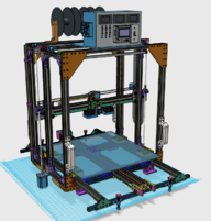
A friend and I decided that we wanted a 3D printer that could print large objects. We first thought one cubic meter might be a good size. That quickly was revised to a half cubic meter. The printer was designed using Open Builds parts library on Autodesk's 123D Design (Since Discontinued by Autodesk, but still my goto 3D design software.)
The image of the BA3DP at the top of this post is a screenshot of the design in 123D Design as it is now. (By the way, BA3DP stands for Big Assed 3D Printer.)
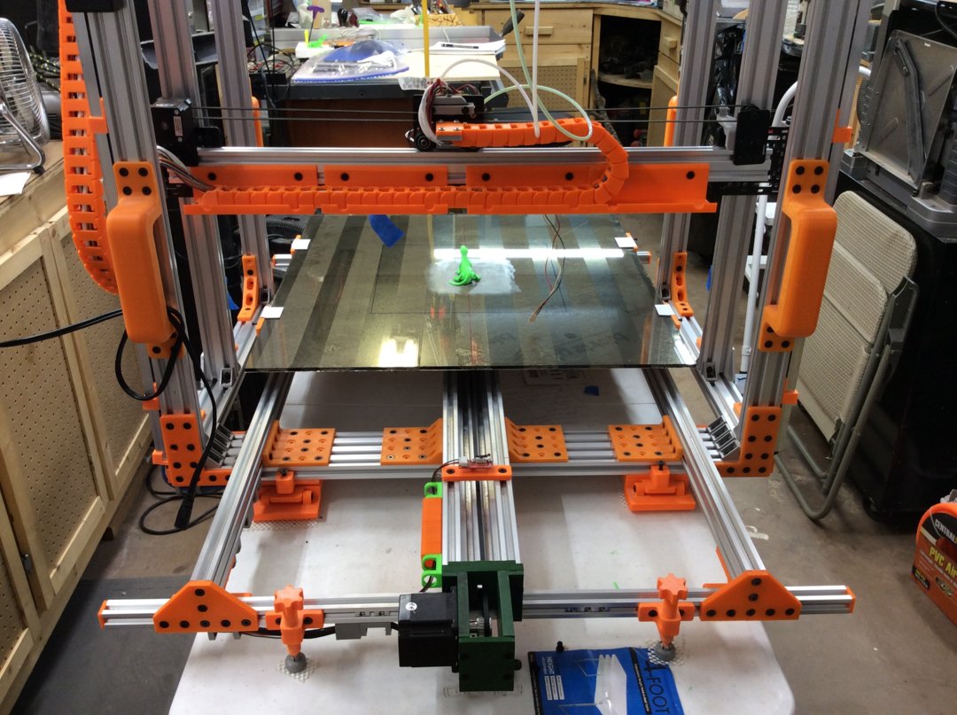
This is a photo of the BA3DP sitting on its table in my shop. It just finished printing a green Gecko.
The design takes into account that for precise 3D printing, a prime requirement is that the printer frame be as rigid as possible. If the frame twists, bends or moves in reaction to the mass of the X axis with the mounted 3D Print Hot End, layers will never align properly to produce decent prints. So to prevent wracking and movement of the frame, 3D Printed Gussets and stabilization parts were designed to be installed on the aluminum extrusions. The big orange triangular Gussets seen at the top of the printer are examples. All the orange parts in the photo, (orange being my friends favorite color) are mainly there to make the frame rigid, and to reinforce the connections of the Aluminum extrusions. Note the handles on the vertical frame extrusions, these make moving the BA3DP a little easier.
In the photo the build plate is a sheet of tempered glass. Laminated to the bottom is a thin sheet of steel that was originally used to enable a proximity sensor for bed leveling. Although this worked well, it was changed to a method where the hot end nozzle is placed against the glass and driven downward until a limit switch is activated, the software offsets are used to provide the proper printing distance. This is done 9 times to map the bed. (I adapted this idea from my ROBO 3D R1 Plus printer, which incidentally, printed the gussets and brackets.) The original build plate was a solid 1/4 inch thick aluminum plate. It worked fine, but the mass was too much for the C rail and stepper motor to move at normal printing speed. Steps were lost during printing and ruined the prints.
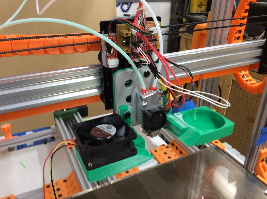
This is a photo of the X Axis and the Hot End. This hot end accepts two filaments fed by two separate filament drive motors mounted on the top rear of the frame. Some of the reinforcement brackets can be seen in the background. There are many more holes for attachment than were really necessary, but it was easier to provide more holes than required than to go back and redesign the part with more holes. The brackets seen here connect the bottom 20 by 80 aluminum rail to the outrigger 20X40 V rail. They are also used to connect the 20X80 to the "C" Rail used for the Y axis.
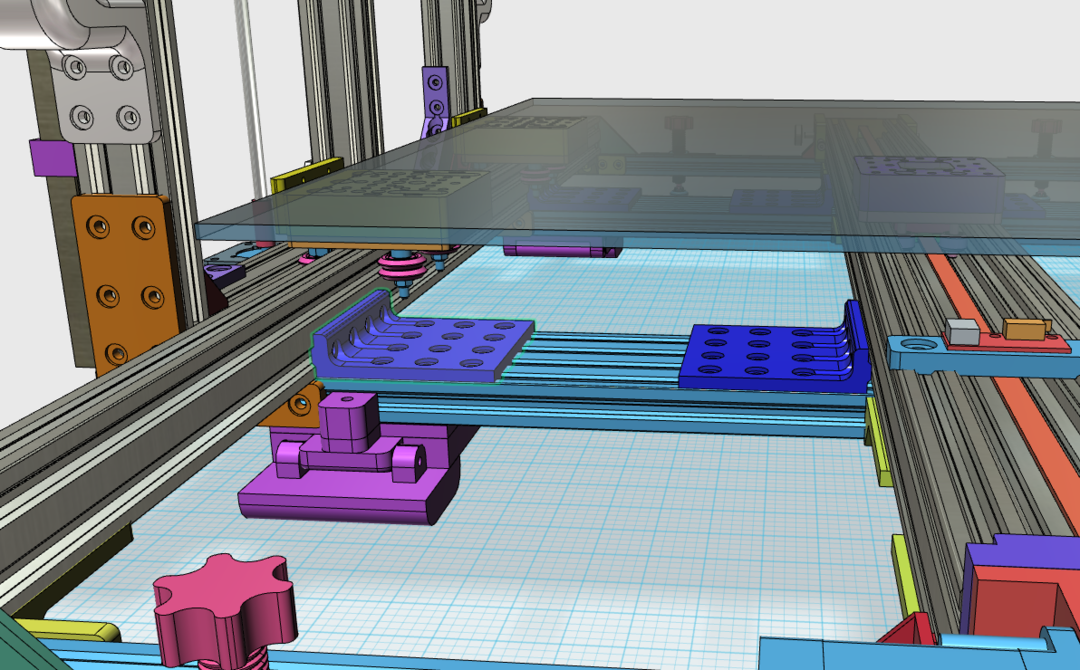
Above is a screenshot from 123D Design of the brackets. Note the "feet" (purple) that allow leveling and adapting to not quite flat surfaces.
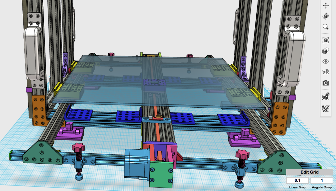
Above is a screen shot from 123D Design showing the rear of the BA3DP. The "C" rail moves the build plate from back to front providing the Y Axis. The stabilization brackets can be seen connecting the bottom 20X80 rails to the C rail and the outrigger rails. The 3D printed plates that the V rollers mount to, the Yellow Plates, use the V rollers on the top V groove of a 20X40 rail on the sides, which I call the outriggers.
This is a photo of the actual BA3DP from the rear. The motor mount is probably a bit of overkill, but it is very rigid and provides smooth movement of the Y axis, or build plate. The X Axis motor is to the left mounted on the Z Axis bracket, the X Axis drive belt idler is on the right mounted to the other Z Axis bracket. The brackets are Open Builds Plates which also hold the V rollers for the Z Axis, the home switch bracket for the X axis, the X Axis rail, and the Acme Screw Nuts for the Z Axis.
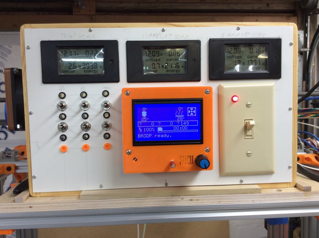
Above is a photo of the control box for the BA3DP. The meters across the top monitor power usage. The left one is total power from the 12 Volt PS. These meters measure the voltage and current, and then display the power used in Watts, and also the energy used over time. The middle meter monitors the 11 amp power usage of the RAMPS Board, and the right meter monitors the power usage of the 5 amp circuit of the RAMPS board. These are not really necessary, but we felt more comfortable knowing the power usage so we did not burn something up.
In the enter is the LCD display that shows what is going on in the Arduino and RAMPS board controller. The big wall switch is the main power for the whole printer which switches the AC to the power supply. The smaller toggle switches are used for accessories, like LED lighting to the X Axis mounted on the Hot End bracket, LED lighting that is mounted to the Top Rail in the front to provide light on the print bed. and also to allow the cooling fans to be turned off or on as required. Each toggle switch has an LED to indicate if the switch condition, lit when on, not lit when off.
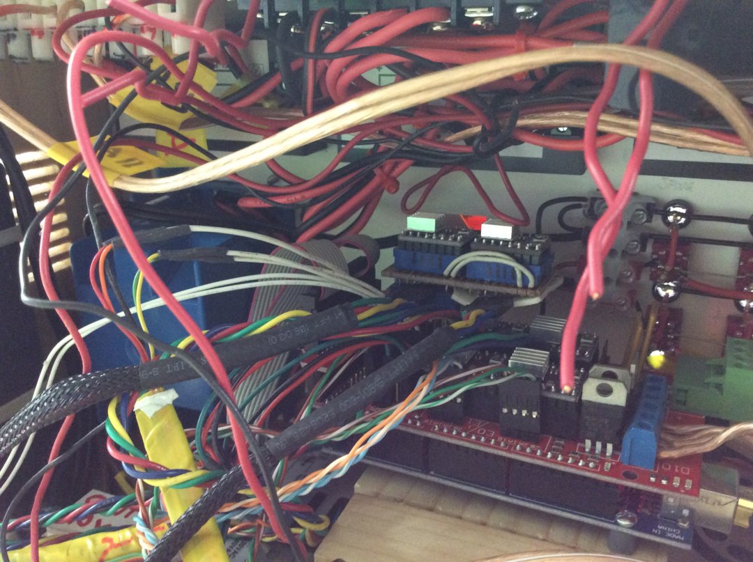
EEEEK! This is a shot of the inside of the control box! Lots of wires. The Arduino Mega 2560 and RAMPS board is seen at the bottom right. The rear of the toggle switches and LEDs are about middle right. A special Z Axis Driver board is almost center. This adapter allows two stepper drivers to be used, one for each Z Motor instead of one driver for both. The power supply is under the Arduino/RAMPS boards mounted to the bottom of the Control Box. The Control Box looks much better with its magnet mounted rear cover on it. (Not Shown) There is a fan on the left side of the Control Box that provides cooling air through the box and out some slots on the other end.
BA3DP
Build in '3D PRINTER BUILDS' published by Bob Darrow, Nov 1, 2018.
A slightly more than one half cubic meter 3D Printer using V Rails, V Rollers, "C" Rail, mounting plates, and a bunch of 3D printed brackets to provide strength and stability to the frame. Rigidity was the goal and precision and accuracy the result. The software is a whole other topic, many weeks spent dialing that in to make the printer print.
-
-
Build Author Bob Darrow, Find all builds by Bob Darrow
-
- Loading...
-
Build Details
- Build License:
-
- CC - Attribution NonCommercial - Share Alike - CC BY NC SA
Reason for this Build
We thought a 3D Printer to print BIG objects would be cool. Building it ourselves? Even Cooler. Having a resource like Open Builds for the V Rails and C Rail as well as motors, brackets, plates, and hardware made this possible. All you need in one place. Unfortunately I do not have the printer anymore, my friend bought my half out and took it to Oregon with him. I might have to build another. -