Another complete novice to CNCing attempting to build his first machine.
First off I would like to Thank Openbuilds for this forum, and Kyo for his very well presented tutorials in building the Sphinx.
I found this website a couple of years ago when building a 3d printer kit from Makerfarm, and their suggestion of getting the power supply from Openbuilds. I was hooked from that day until today. I have probably been here at this site five times a week, in amazement at peoples skills and builds.
Daydreaming of the day when I could do something amazing like one of these builds.
I work in a body shop and the closest I come to microcontrollers, motor drivers, endstops, voltage regulators, grbl and so on is when you put the car on the frame rack and the computer measuring system says yep it's smashed.
The mechanical aspect of the build did not intimidate me but the electronics sure did. Some of the electronics enclosures I have seen look like they should be on the space shuttle not in someone's garage. How would I do that? Hook up the smoothieboard open drain, enable this, ground that. Yea, right open drain - closed drain same thing to me.
Finally, on black Friday of 2017 everything went on sale, so I ordered the C-Beam XL. What was it ....? 30% off even a dumb body guy knows that is a good deal. I had been pouring over Kyo's sphinx build for the proceeding month, debating between that, the XL, or the new machine from Ooznest.
The Ooznest showed a lot of favor as it was a true kit and had directions for the electronics. But for some reason I kept coming back to the Sphinx. I think because it could be scaled to suit ones intentions.
So true to my obsessive/compulsive behavior I ordered the XL and two days later ordered all the extra parts needed to make a Sphinx 1000 x 1000, there went my 30%(believe me I have spent more in worse places).
Enough of the dissertation...let's get to the build.
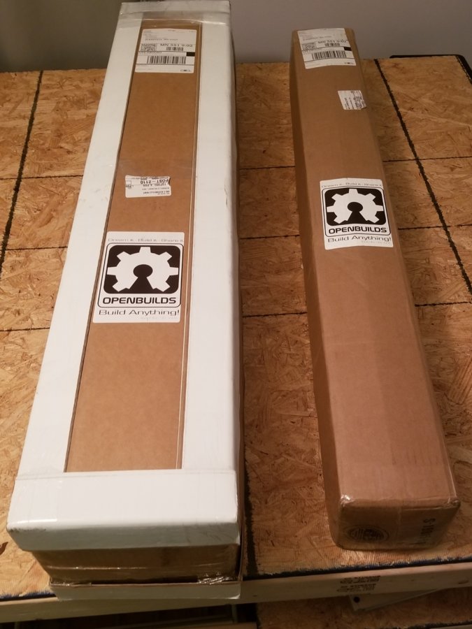
Everything was packaged neatly and secure. Even with the black Friday rush it was here the following Friday.
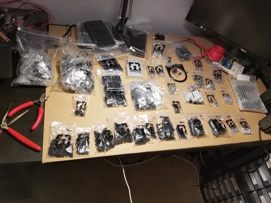
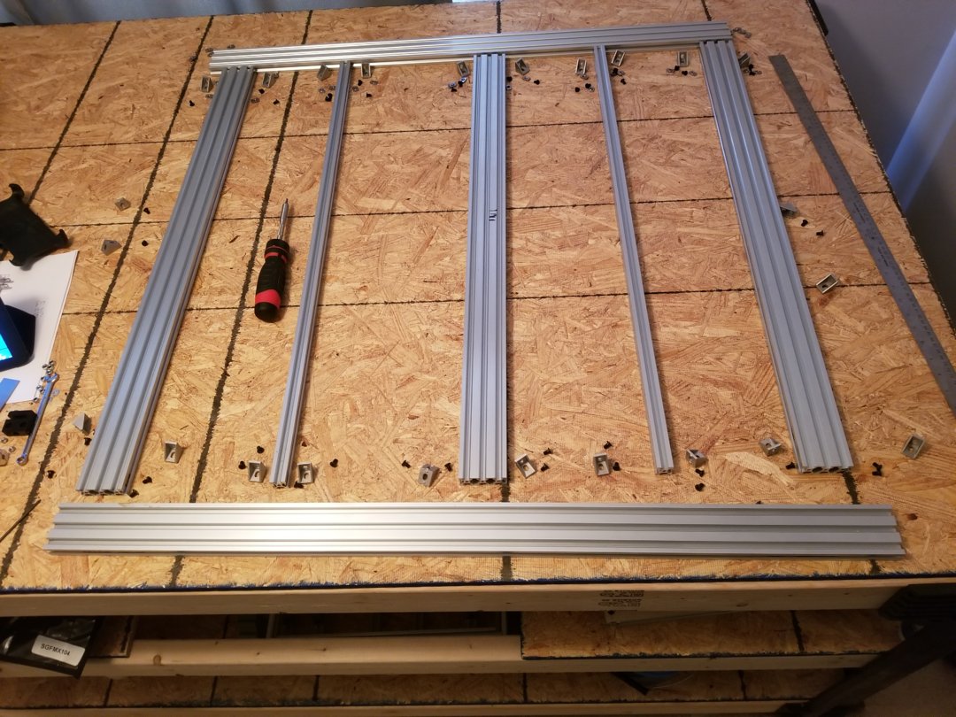
Layout most of the hardware
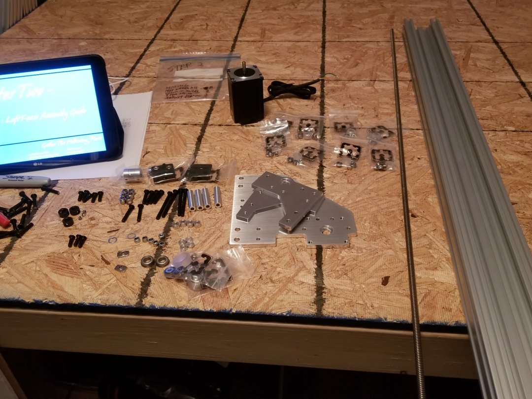
First side of the Y axis. Kyo has the build instructions broken down into steps, so I bagged the hardware for each step before starting the build. Most of the mechanical build happened between the 20th of Dec and the 15th of Jan. on the weekends. Additionally having the directions right there on my tablet was a lifesaver.
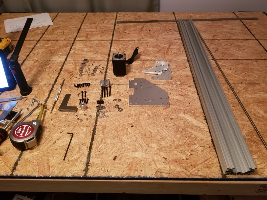
The other Y
The base. Here was my first rookie mistake as I did not put any slide nuts for the spoil board. In the end I just put cast corner brkts and attached to base with drop in nuts. Screwed in to the spoil board with wood screws from underneath. This part of the build was done around Christmas and New Year when it we were in the midst of -10, -20 temps. So yes, I froze my a$$ off out in the garage trimming these pieces.
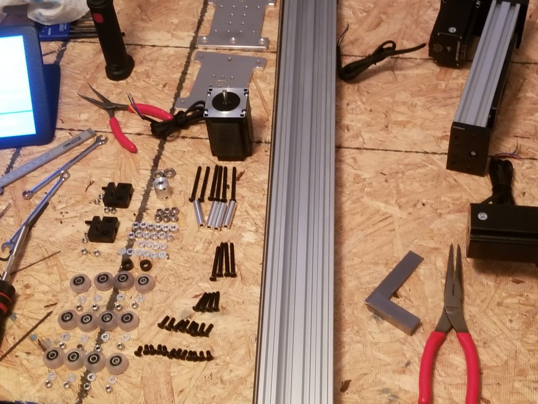
X axis
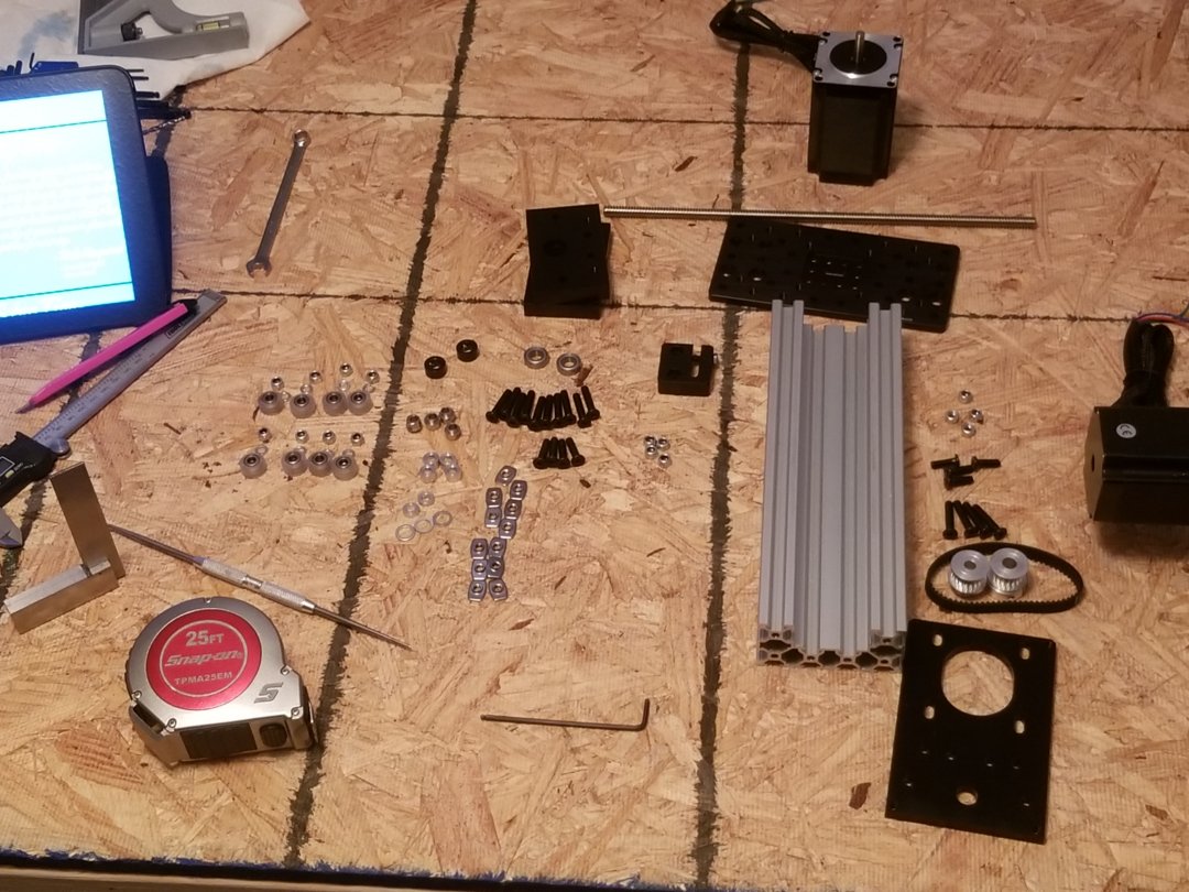
Z axis
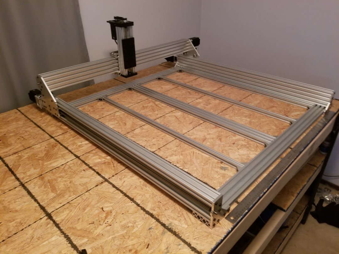
Mechanical build complete
Now, on to the electronics. The area I was/am most apprehensive. Solder pins to the smoothieboard, crimp wires and make connectors. Let me tell you I bet I looked at every available wiring picture on this site trying to figure out what I am doing. Still really don't know. Reading about MOSFET, solid state relays, this that and the other thing, might as well be using Swahili, because I don't know squat about Swahili either.
Ok, now what??

The devils workshop. This is what your bench looks like when you don't have a clue to what you are doing.
I bet I went through 50 wire crimps before I figured out how to use that tool. Every time trying something a little different than the last. Then the AHA moment. I am left handed I was holding it upside down and backwards. After that you would think I had been crimping wires my whole life.
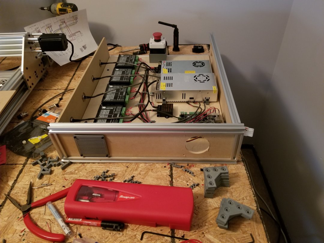
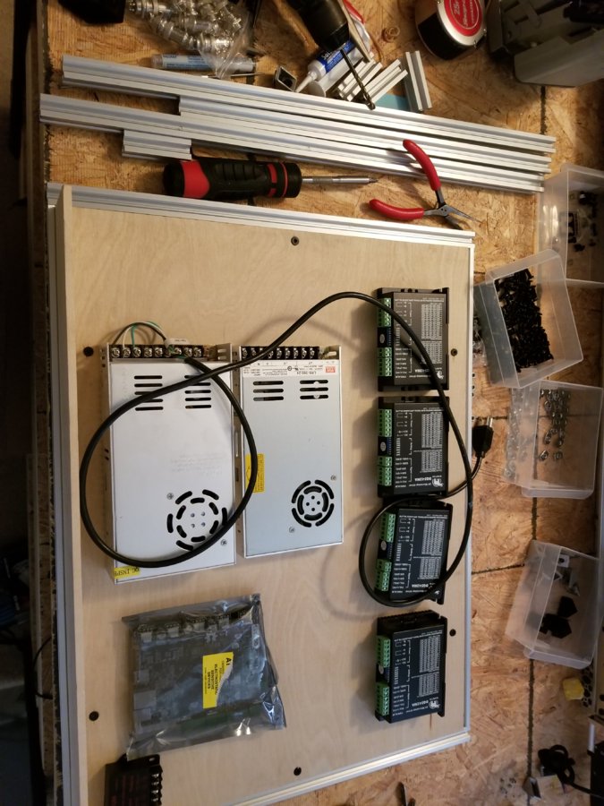
Last summer I had been playing with the linear rail making things, so I had plenty of 20 x 20 laying around. So I made this case to hold the electronics. You can see my professional schematic in the upper left. I didn't want a rats nest of wires, but I still got a rats nest. One power supply is the 24v for the motors, and the other is 12v just for the fans blowing air across the electronics, probably overkill. First rule of a body man "get a bigger hammer"
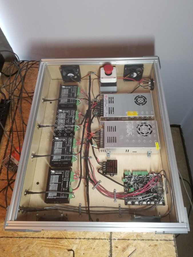
Electronics enclosure complete. That is my second piece of acrylic as my first piece I used a regular drill bit and cracked the plastic going through. Probably could have done it with regular bits if I would have stepped up from small to larger. Nope not me 1/4" right from the rip. Another $20

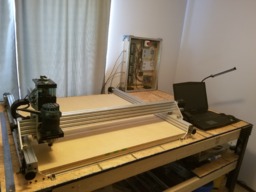
Done!! That is a 4' x 6' table.
Now I have much to do learn about speeds and feeds, fusion 360, where to find dxf files, dust extraction system, part hold down, and much more.
I am already thinking plate maker or laser....
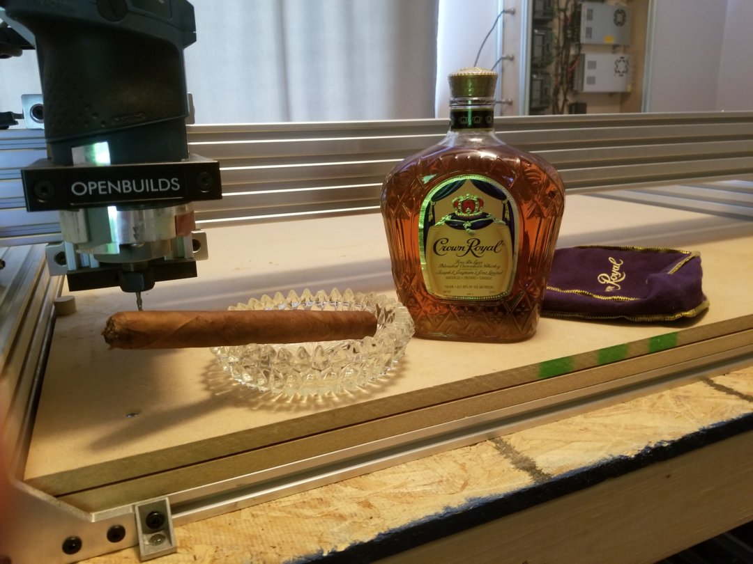
Celebration Time!
Another Kyo inspired Sphinx
Build in 'Cartesian Style CNC' published by MrCalm, Feb 24, 2018.
A 1000mm x 1000mm copy of Kyo's Sphinx
-
-
Build Author MrCalm, Find all builds by MrCalm
-
- Loading...
-
Build Details
- Build License:
-
- CC - Attribution - CC BY
Reason for this Build
To cut plastics...delrin and pvcInspired by
Kyo, BeardyBlair -
Parts list
Qty Part Name Part Link Comments 1 Sphinx plates Link Blue Ox Solutions