
First, I have to say that my first language is French, so please forgive me if I make typos/grammatical errors!
I was first introduced to CNC from a friend on mine who is a professional woodworker. After visiting him after his acquisition of a Shopbot CNC, I was fascinated by the almost limitless possibilities of his tool. I started browsing the Web for ideas and finally decided to buy the plans for a MDF base table. I had my friend to cut all the parts on his CNC and it was just a manner of assembling everything with a ton of bolts and screws!
I rapidly reached the limit of the table as far as the size of sheet it could accommodate. The table had a limit of 37 x 90 inches and it was impossible for me to work from a 4 x 8 sheet. So it didn't take me long to get on the drawing board to design a table that would last me forever I hope.
When designing my new table, I also planned for the future by using heavy metal for the base as I plan to add Plasma facility whenever finances allow me to do it! This mean loading heavy sheets of metal weighting a couple of hundred pounds.
I have a computer programming/analysis background and by far I'm not really good at using 3D software, so I opted for Sketchup to make my design.
The first thing I did was making a proof of concept for the Ox gantry. I used my old CNC to cut parts in wood that I connected to some linear rails, wheels and spacer blocks I ordered from OpenBuilds. I wanted to see how feasible my idea was before investing in my project. I included a few pictures of my proof of concept with the gantry made of plywood/MDF.
Once I was satisfied with the results, I went ahead and design the gantry plates for the Y and Z axis using the Ox model as a base. You can see a few pictures of the plates I cut with my old CNC using 1/2 aluminum plates.
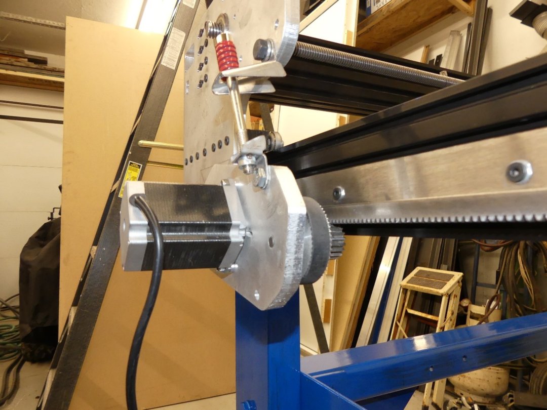
I tried to use parts from my old CNC to save as much as possible. For the Y and Z axis I'm using Hi-Lead Screw, 5/8 X .250, RH and Nema 23 motors. For the longer X axis, I decided to go with rack and pinion. I used the DXF file from CNCRouterParts to make my plan and then cut the Standard Rack and Pinion Drive, NEMA 23 plate in 1/2 aluminum. I then ordered from them the rack, pulley, belt and drive spindle to complete the X axis
I'm presenting the project in the same order I created the different parts. I started with all the moving parts since I could cut them on my old CNC. Once I had all the gantry and other parts done, I assembled them to see if they were fitting on the rails.
I made a big mistake for the first part of my build where I forgot to upload the images as "full image" and they appeared as thumbnails.
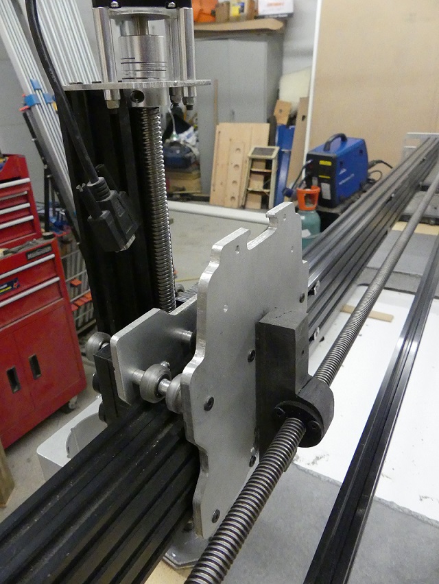
This is the gantry representing the Y and Z axis.
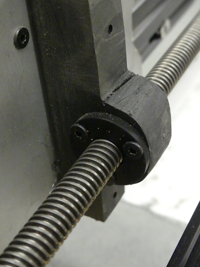
This is a close up of the screw and the flange nut that are attached to the plate with a hi density type of plastic that I cut with a band saw.
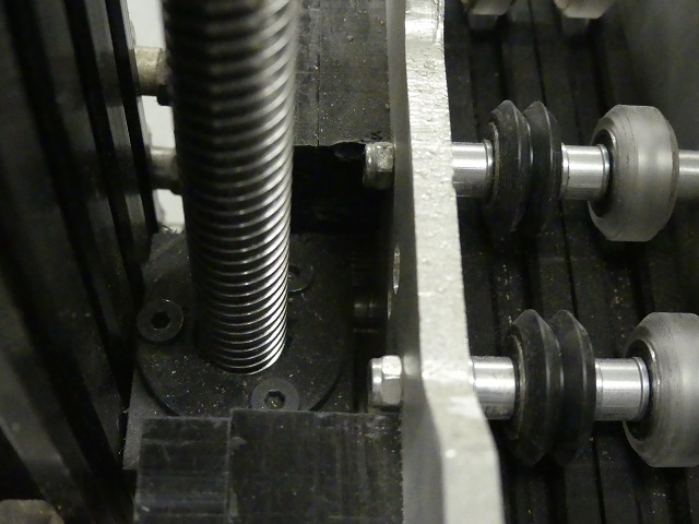
Here is the connection for the Z axis using the same principle.
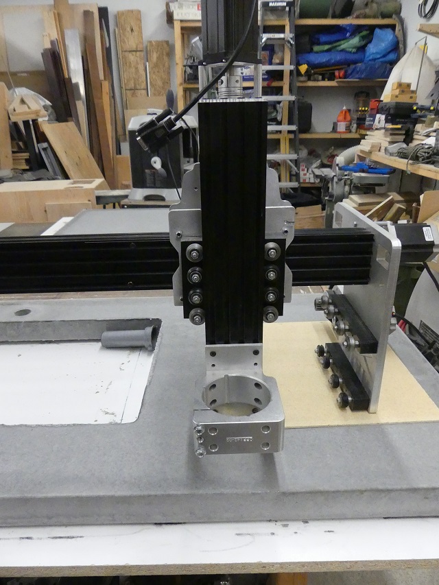
Here is a front view of the gantry with the router bracket.
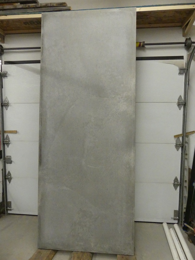
My workshop is kind of a mess right now because a friend of mine asked me if he could come over and make his concrete countertops for his new home in my shop as he didn't have room at his place and he was a bit in a rush. You can see one of the countertop under my gantry and another one behind in the previous picture. This put me a bit behind schedule to complete my project and I lost a total of 8 days where I couldn't work on my table as we also used my new metal base for the big island countertop. On the other side, this allowed me to test the solidity of the table since the countertop alone weighted close to 725 lbs plus one sheet of MDF and 3/4 sheet of melamine for a total of around 800 lbs. Here is the big countertop 40 x 100 inches)!
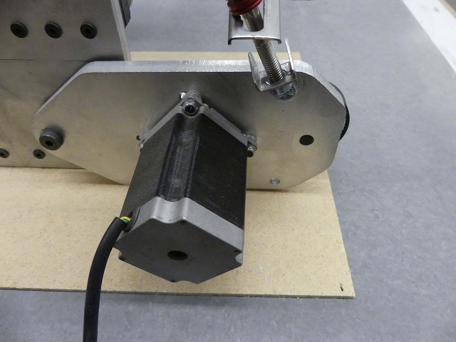
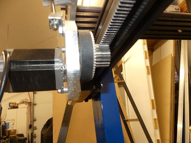
Here you can see one of the motors for the X axis mounted on the rack and pinion drive that I cut with my old CNC.
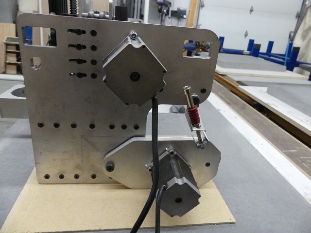
And a more global view of one side of the plates for the X axis.
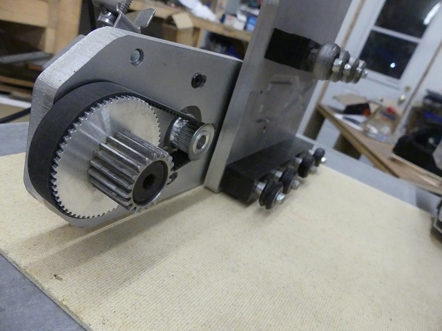
And finally the back of the rack and pinion drive with the rack, pulley, belt and drive spindle.
And now, here are the steps I took to build the metal base.
The legs are made with metal C Beams that are bolted to Angle Irons and metal plates to make sure they are all square. There are also Angle Irons bolted at the bottom of the legs to complete the process of squaring the whole project.
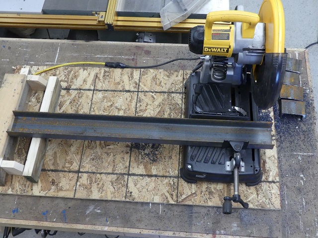
All the legs had to be cut to the same size, so I used a stop block to repeat the same cut 10 times.
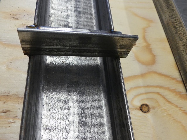
The only part I had to weld is at the upper part of the legs to support the Angle Iron that runs from front to back of the table.
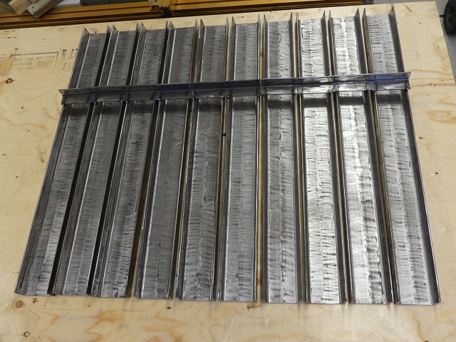
And 10 legs completed!
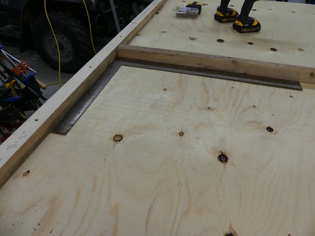
Squareness is very important and this is why I made a jig to assure all angles were 90 degrees perfect.
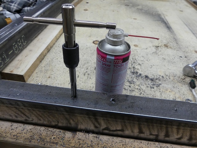
The table is hold by bolts and everything is hand tap. All it takes is a lot of patience and cutting oil to lubricate!
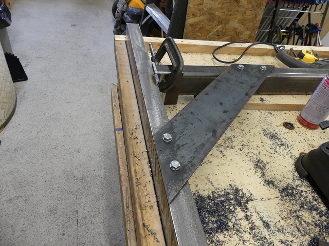
I'm putting braces on each upper corner of the table to join the legs to the transversal support to square the table and also to add strength.
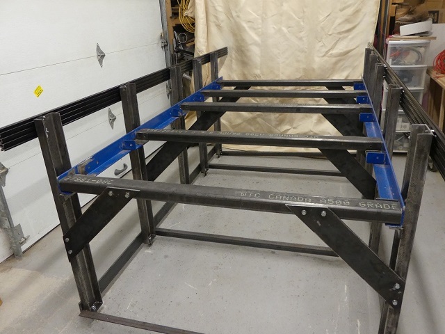
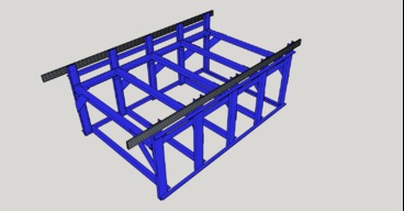
Here is a picture with the table fully assembled before painting.
And the moment of truth! This is when I connected the gantry to the side rails. It was a relief to see that everything was fitting perfectly.

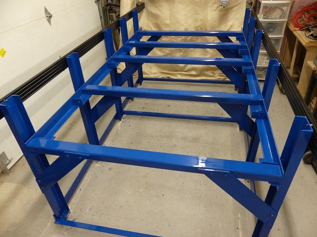
The table with its final colour.
Rails with the rack installed for the X axis.
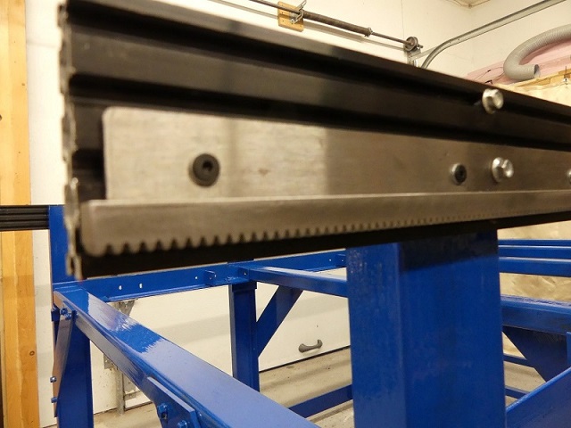
A close up of the drive spindle and the rack working together.
Next step will be to add the electronics.
More to come...
All metal Ox hybrid CNC Router Table
Build in 'CNC ROUTER BUILDS' published by Denis Lapratte, Feb 19, 2018.
This is my second CNC build, but the first one that I design from the ground up. The base is all metal because I want to add Plasma facility later on. I used the Ox model for the gantry plates and made a few changes to adapt to my design. Since I wanted to use parts from my first CNC to save as much as possible, I kept the 5/8 Hi-Lead Screw I had from Roton for the Y and Z axis. I will also add a downdraft table to keep all parts tight on the table for cutting.
-
-
Build Author Denis Lapratte, Find all builds by Denis Lapratte
-
- Loading...
-
Build Details
- Build License:
-
- CC - Attribution NonCommercial - Share Alike - CC BY NC SA
Reason for this Build
I wanted a CNC table able to accommodate a 4 x 8 sheet of plywood/MDF and also make it rock solid as I plan to add Plasma facility later on.Inspired by
Gantry was inspired by the Ox design. I plan on using some ideas from some of the plasma tables projects from the current builds. -
Parts list
Qty Part Name Part Link Comments 0 Link To come


