This is a working prototype, not a solid design, but it works very well, and is capable of placing reliably 0402 and 0.4mm pitch BGA components. Building the machine would almost certainly require adjusting the shapes of some of the 3D printed elements.
Machine in action
Example of capabilities
Approximate build steps:
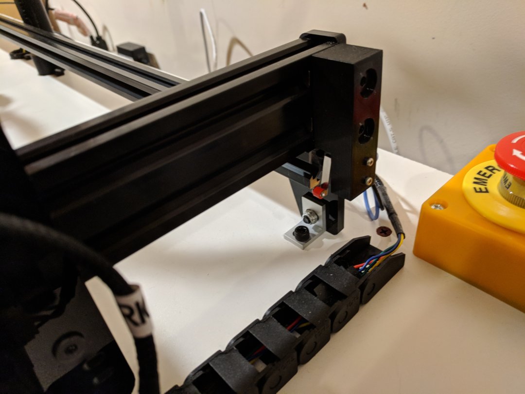
1. Build Acro XY frame. Attach drag chains on both sides.
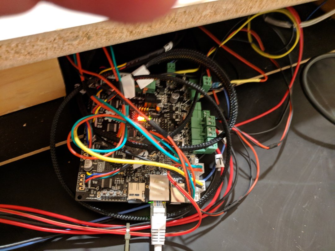
2. Connect power, Smoothieboard, test XY movement.
3. Make three holes in MDF board: one in the middle for bottom vision, two in the back for cables.
4. 3D print Z-axis box, cable vertical holder, cable hole holder, end stops.
5. Attach end stops, connect to Smoothieware, test XY homing.
6. Cut Z-axis lead screw to proper length.
7. Assemble Z-axis box, connect, test Z movement.
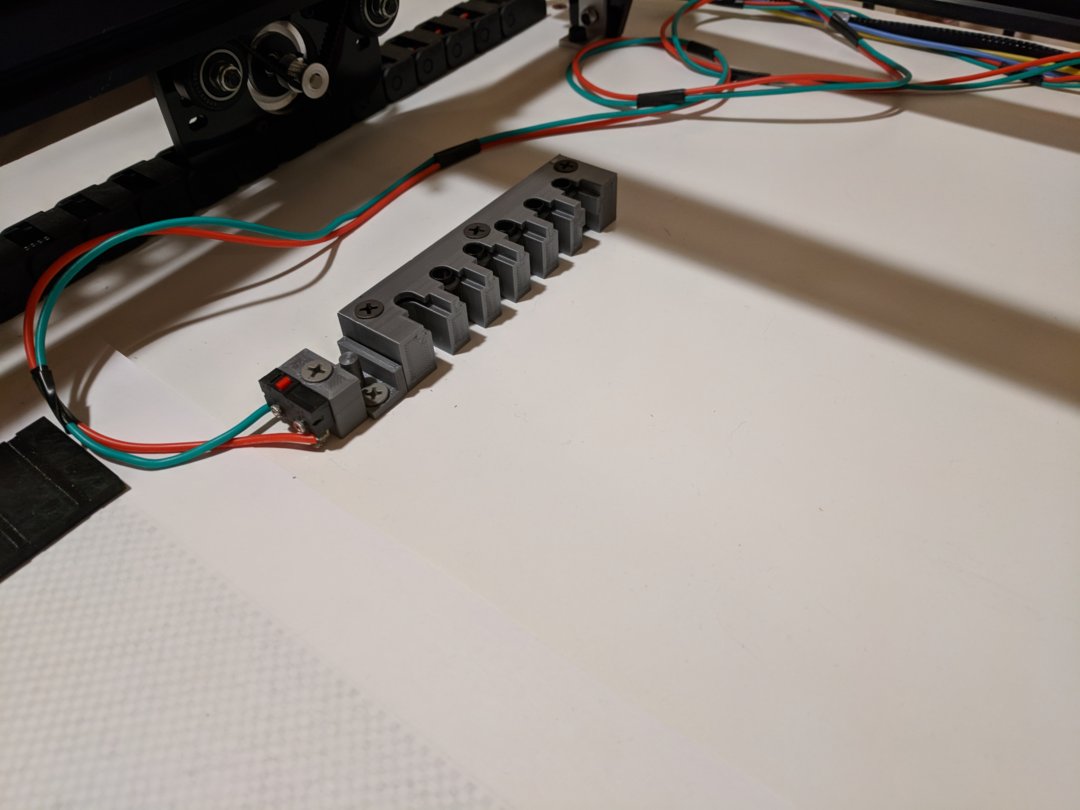
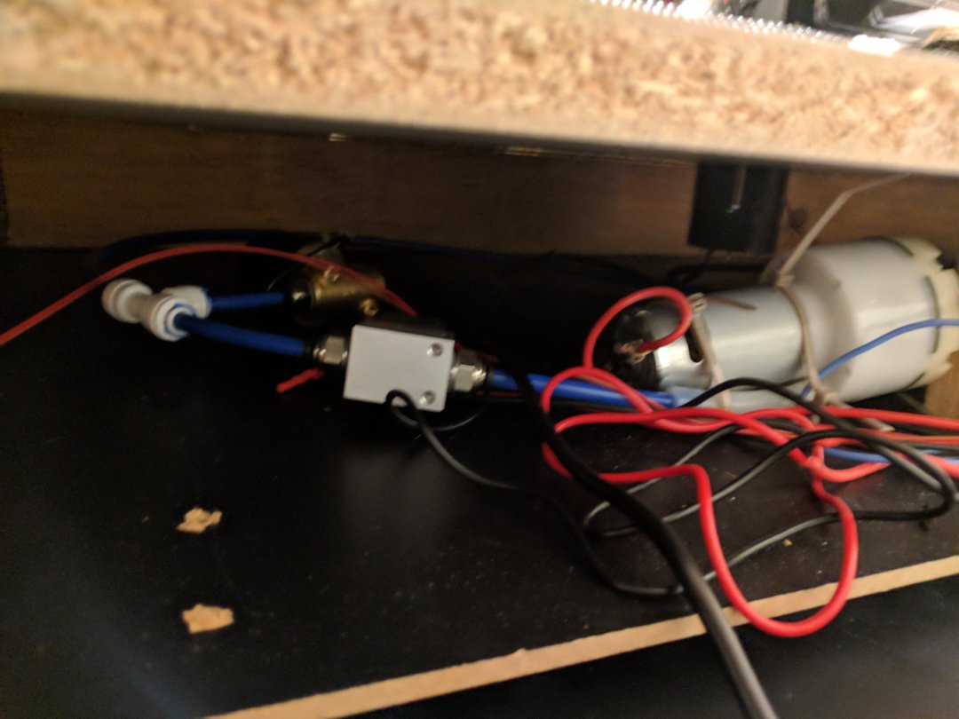
8. Attach flyback diodes to vacuum pump and two valves.
9. Connect vacuum pump, valves, to Smoothieboard, test switching.
10. Run vacuum tubing to Z-axis box.
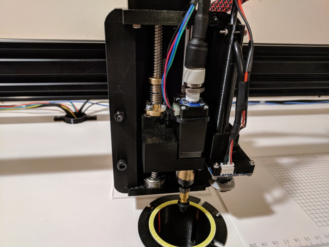
11. Attach rotating coupler to vacuum tube and Nema 8 motor.
12. Glue 5mm coupler to nozzle holder using epoxy glue (pre-drill the holder if needed).
13. Attach 5mm coupler with nozzle to the other side of the motor.
14. Attach motor with nozzle to the Z-axis carriage.
15. Test pick and placing action using manual G-code commands.
16. 3D print bottom camera holder, upper camera holder, nozzle holder box, and Z-probe.
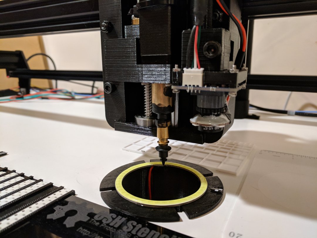
17. Attach bottom vision camera to bottom camera holder.
18. Attach 2x4 beams to the bottom of MDF board.
19. Pre-install bottom vision camera, glue 60mm LED ring on top.
20. Connect LED ring and test light intensity with G-code commands.
21. Attach XY frame to MDF board.
22. Attach upper vision camera to the camera holder.
23. Attach 40mm LED ring to the camera (epoxy glue?).
24. Pre-attach upper camera holder to Z-axis box.
25. Align both cameras with XY frame, do final attachment.
26. Install nozzle holder box and Z-probe.
27. 3D print tape holders, attach to the board.
28. Configure software (OpenPnP highly recommended) with proper values for camera offsets, etc.
CAD files available here.

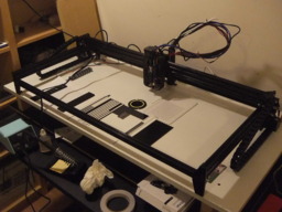
Acro Pick And Place Machine
Build in 'Everything Else' published by Greg Wroblewski, May 13, 2018.
This is a machine for placing SMT components on PCBs. It is based on Acro system, off the shelf parts, and a number of custom 3D printed elements.
-
-
Build Author Greg Wroblewski, Find all builds by Greg Wroblewski
-
- Loading...
-
Build Details
- Build License:
-
- Apache License 2.0 (Apache-2.0)
Inspired by
OpenPnP, LitePlacer -
Attached Files:
-
Attached Files:
-


