
The objective is to have a 5 axis CNC mill: X, Y. Z, A-Turning and B-Tapering. (Note: Until I learn how to CNC the A and B Axes; I will continue to do this work manually. But my dream is to be able to do ALL CNC work on the 5 axes; just as soon as I learn how to do it.)
Please look at the following before continuing:
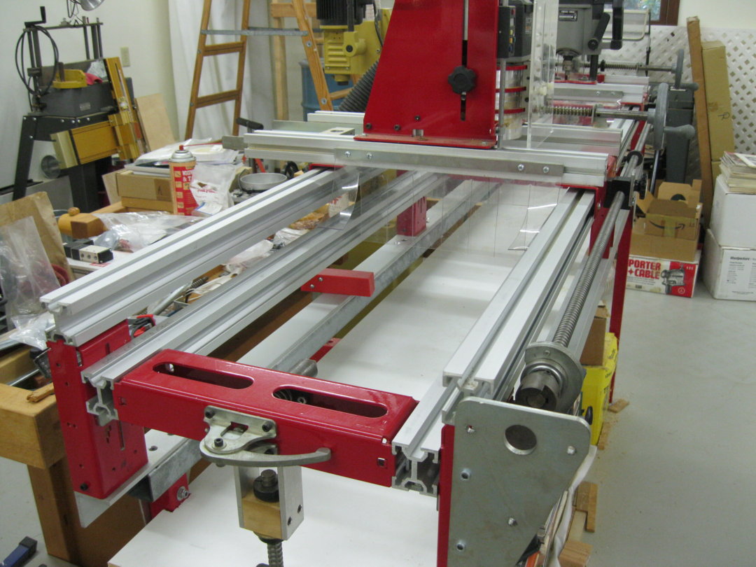
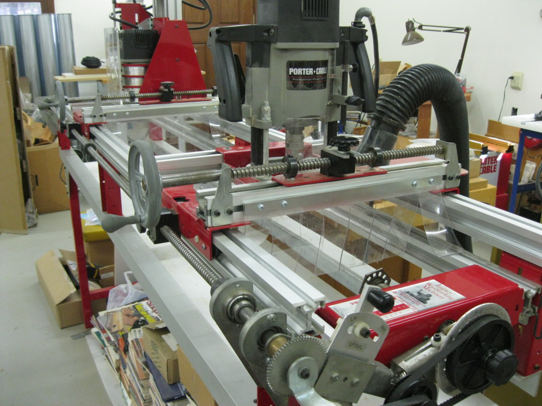
The smaller router and carriage is presently used for all "flat" work. The other for turning and/or tapering. The dimensions of the machine now are (imperial) "X"=19.5", "Y"=84" and "Z" is 7". When this "Build" is completed the smaller carriage and router will no longer be needed. I will do most of the flat work on the left end using CNC control. The right end will be for turning and/or tapering manually.
Note: I will not be limited to one end or the other. IE: I can use the CNC for the entire 84". The same for turning (manually) and/or tapering. However, I will have to remove the router and carriage when I wish to use the CNC milling on the entire 84" of the "Y" axis. But that is VERY easy to R & R.
I will be back as the build progresses. It will be slow. I am as green as a gourd. But "lovun evah" minute of it. LOL Done watched over a 100 videos. Wow. "Caint" wait!
Thanks for watching.
p.
November 21, 2017.
Let's begin........................
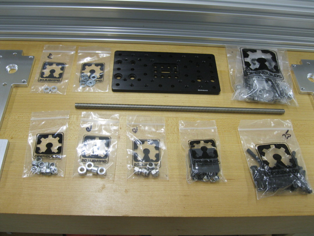
Last night I received a package from OpenBuilds. Check out the photo below:
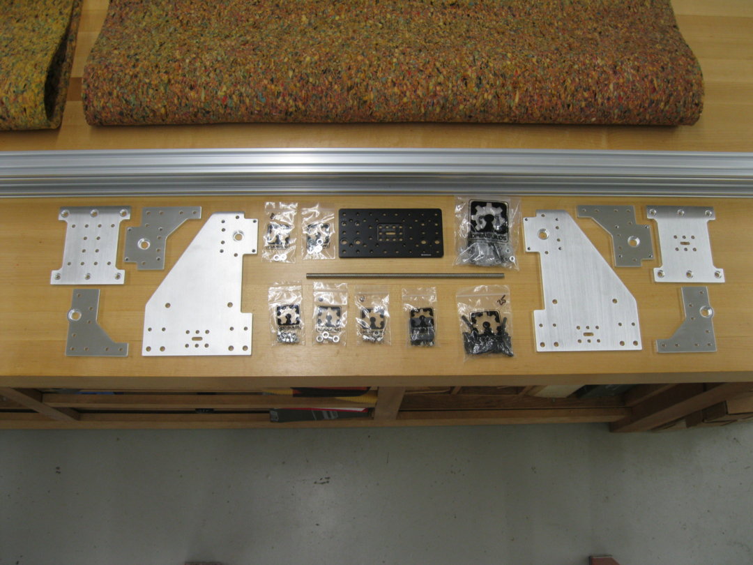
I also received a package from Chris Laidlaw (one of THE most kind persons I have EVER known); containing a set of Blue OX "plates"; that I will be using to upgrade my Ornamental mill to a CNC mill.
Note: I will be using the original OX "Z" plate; instead of the beefier "Chris" plate. Reason: I want to make use of as much of the "X" space as I can. Using the wider 4 hole plates robs me of some space. Thus the black "Z" plate is 3" wide; and it is no wider than the "Z" C-Beam. This puts the router bits closer to the "Y" plates at each end. In time, if I find that the spindle will not be dead "firm", I can always change to the 4 hole X and Z plates; and give up the 2" of X breadth.
Note the Photos below:
I did not order the Sphinx "standard" length C-Beams. Reason:
1. The standard "X" length is 503 mm. Mine is 543 mm.
2. The standard "Y" length is 503 mm (I think). Mine is 2,133.6 mm.
3. The standard "Z" length is (not sure). Whatever it is, mine is taller.
4. I can not purchase the "Y" C-Beam that long; except from "Ooznest" in the UK. Praise Jesus they will do it, cutting it to exact length; albeit a big increase in price, of course, due to shipping, duties and Fed-Ex fees. Help OpenBuilds! This should not be!
Thus: I ordered the maximum 1500 mm C-Beam; and I received it last night from OpenBuilds Parts (shown in the photos above). This will permit me to cut the "X" and "Z" C-Beams to fit my machine; and to "test fit" it; to experiment HOW I am going to install the "Y" beam to my Ornamental mill.
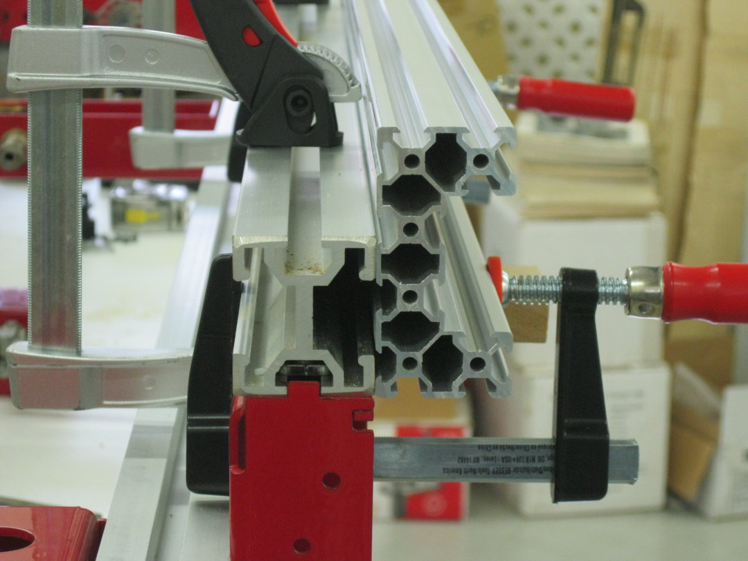
See the following photos and notice the temporary 1500 mm C-Beam clamped to the original top front rail; to see how it is going to look and work:
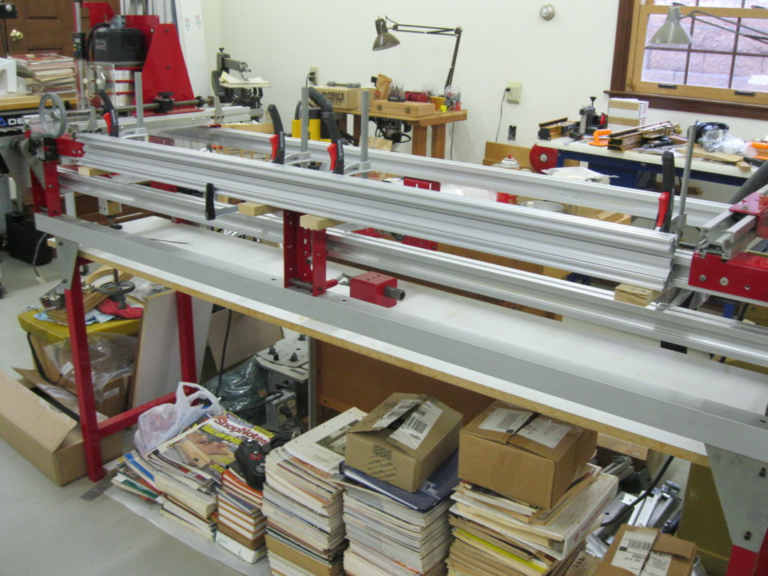
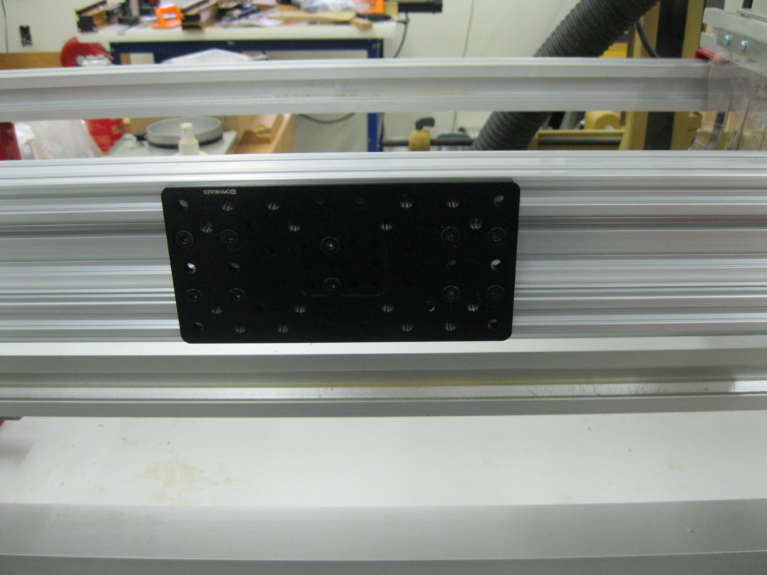
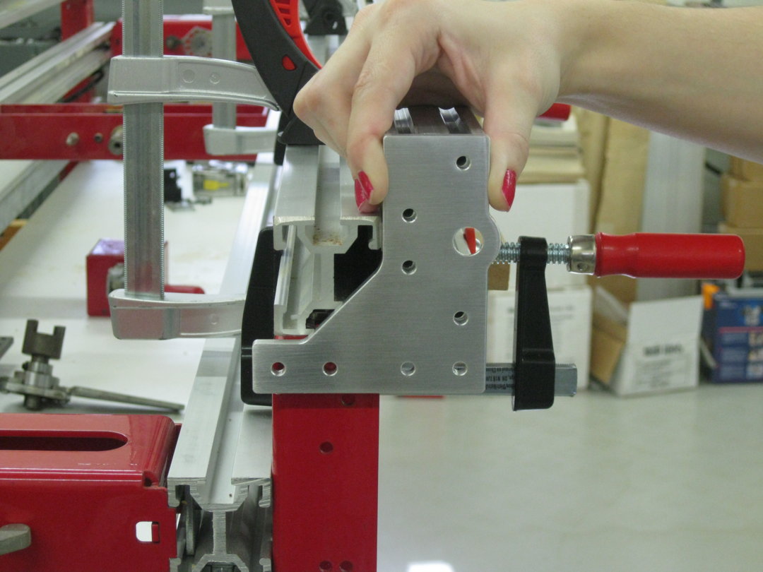
Note: The black extra large "Z" plate on the temporary 1500 mm C-Beam; that I am using to test it. In doing that I solved another problem. And that is: since my original top rails on the mill are no longer capable of supporting the router carriage; because the new C-Beam will be in the way; now the router carriage will ride on the "Y" C-Beams.
So I found a way to make this work like a charm, and a true blessing to boot. IE:The Ornamental Mill's carriage is exactly 12" wide. The black "Z" plate is just a little over 6" long. I will use 2 of them in the front of the carriage; AND 2 on the back of the carriage (8 wheels each in the front and back). And the threaded holes in the black plate, are in perfect alignment with the carriage. Right down to the mounting of the split screw being bolted to the plate; rather than the carriage as it is now. This makes use of the original location of the Ornamental mill's lead screw. That is NO coincidence guys. NO way! Wow!
Note: The front plate of the carriage will be installed over and in front of the black plates; and the same for the rear carriage. I believe that will be perfect. Thankfully.
Hallelujah!
That is all so far.
Stay tuned. I will back on the air when I get the long C-Beams from the UK after I break the bank; and have enough "budget" for all the other goodies to put the rest together. Oh Well LOL.
"So long for now!"*
* Courtesy "mrpete222" on "YouTube". Check him out. You'll love him.
GAR-OWN-TEED!
November 28, 2017
777 CNC update;
We will begin in correcting what might be a major problem. IE: Above I have labelled the long axis "Y". But the more I think about it, I believe it would be better to label the long axis "X", and rename the short axis "Y". I rationalize that this would be better when I get to G code; and also, that is how they labelled it on the original "ornamental" mill. Any suggestions will be welcome.
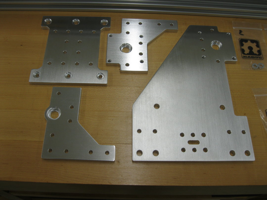
The second problem was: The former "X" plates and the black "Z" axis plate have been changed. I sent back the two 3-hole "X" plates and I will no longer use the black extra large "Z" plate on the "Gantry". Bless Chris' heart, he was kind enough to take them back and send me 3, 4-hole plates and I paid the difference. Check out the following photo, showing the new 4-hole plates:
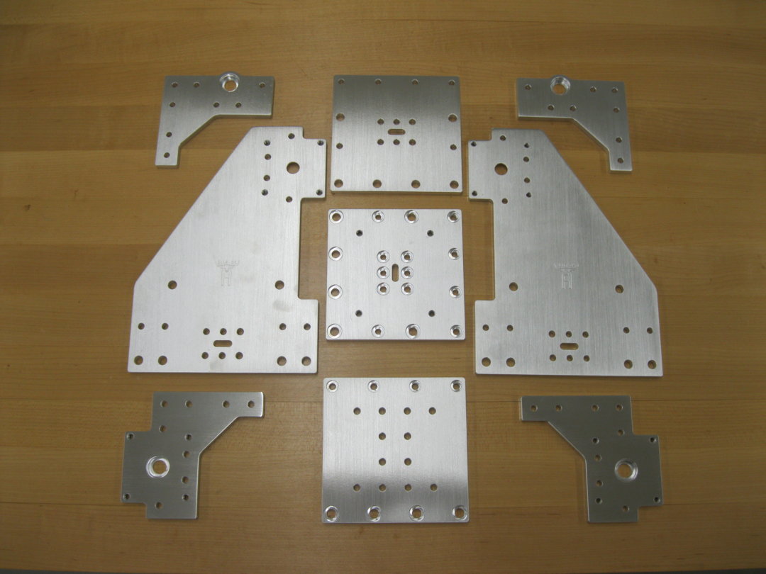
I was trying to get the maximum width (front to back of my Ornamental Mill) on the short "axis". So I originally ordered the 3-hole plates. But I realized immediately I gained nothing. Stupid me.
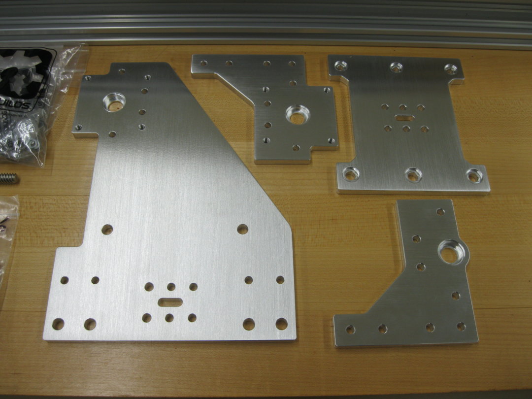
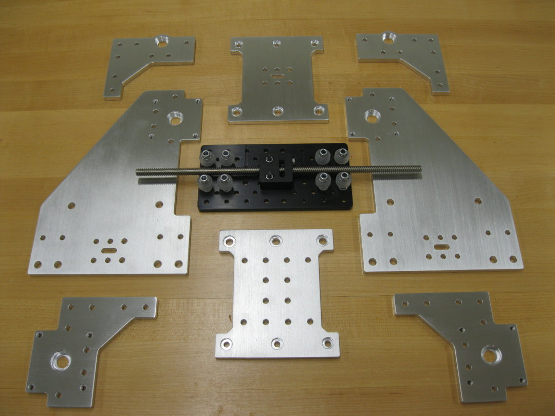
Also, I ordered 3 more "Z" plates to support the router and carriage; as discussed in the last update.
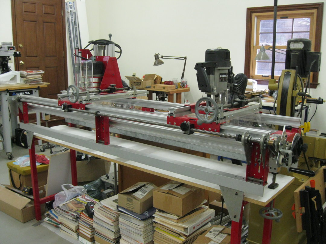
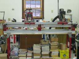
Then I cut the 1500 mm C-Beam in half; and temporarily clamped both pieces on front and back of the Legacy Mill. Check out the following photos:
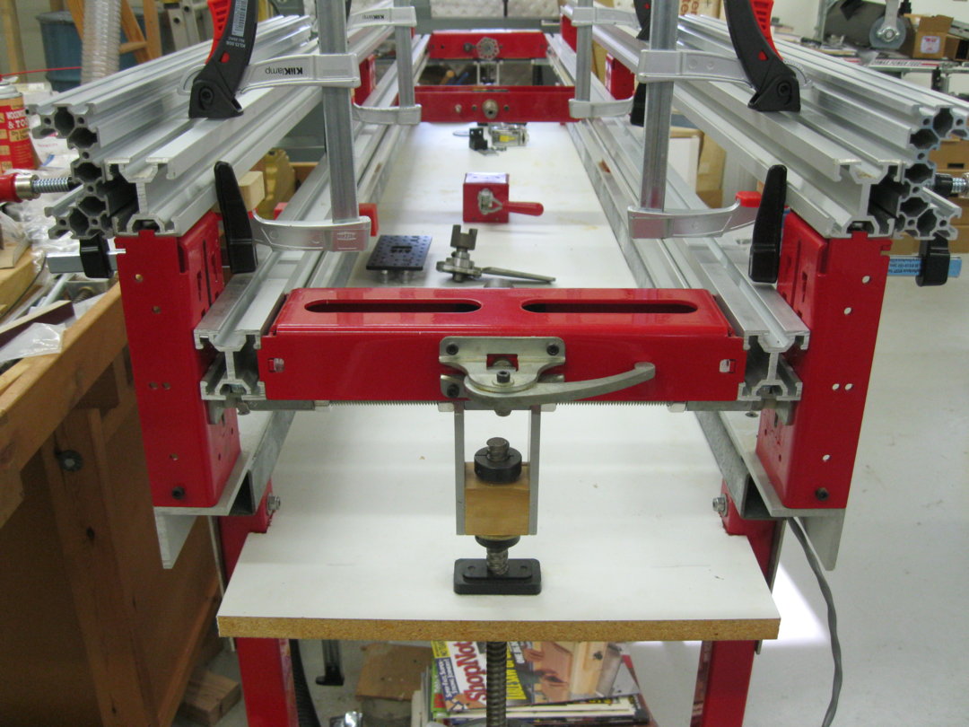
I will install 5 mm "T" nuts in the 2nd row up (on the inside of the C-Beam) every 6" along the length (2,133.6 mm) of the C-Beams. Then I will drill a corresponding number of countersunk holes in the original rail extrusions; and use 5 mm screws to permanently attach the C-Beams to the top two existing extrusions. To further anchor the beams; I will bolt the "end" plates to the existing red legs and one self tapping screw in the existing extrusions; as well as bolt them to the ends of the C-Beams with four bolts. This should anchor it well and it will be very strong, I believe. In testing it today, It seems UN movable, yet it is just installed temporarily. Yippee! Praise Jesus.
See the following photo:
Note: I will then cut off the bottom left of the end plates; to make it flush with the inside edge of the red legs. The cut will create a half hole in the End Plate, but that will be ok.
Finally: I took advantage of Black Friday and ordered over $500.00 worth of parts from OpenBuilds; to work towards the fruition of this undertaking. I have decided to not use "stepper" motors. Rather; I will use Clear Path "servo" motors and a Centroid "Acorn" controller. I will use a 24V P.S. to feed the controller and a 48V P.S. will feed the servo motors directly. At this stage of the game, I am not going with a water cooled spindle. Rather, I will use, for the time being, a 3.25 HP Porter Cable router. Of course one day I will switch to the more quiet spindle.
Also, it is possible that I will not use a servo motor on the "Z" axis; ONLY to stop a problem that is intrinsic on servo motors. That is: if they lose power the router will fall by gravity. Then again, I also might use an automatic "stop"; to get around this problem. Another solution might be to make the "pitch" of the "Z" lead screw tighter. Not sure as of now. Time will tell.
That's all for now. Please stay tuned for the next update of the "777 CNC" coming to life. May He bless you all always,
p.
777 CNC Build
Build in 'CNC ROUTER BUILDS' published by patdee, Nov 29, 2017.
To begin the "Build" I have ordered a few parts from OpenBuilds to get started. They are arriving today; according to "tracking". I cant wait! Praise Jesus! This 85 yr old man is getting a "New " life. Hallelujah and amen. Because I am building this on an existing machine, I have to be careful; so I will order some parts then see what I don't need (such as a base); along with parts that I may need to adapt it to the machine. It should be fun! "Caint wait!"
-
-
Build Author patdee, Find all builds by patdee
-
- Loading...
-
Build Details
- Build License:
-
- GNU (LGPL3+) Lesser General Public Licence
Reason for this Build
Got the bug as alwaysInspired by
KYO and Michael