
I really liked Pedro's design and after a few quick chats with him, he seems to love working with it.
After analyzing his post over many weeks, I finally decided that this is something I wanted to go ahead with. Although I would be making some key changes to suit my own needs.
I did this sketch in MAY-CAD.
Firstly, I chose to use linear rails rather than wheels for the Y axis. I found that the cost difference was small enough to go that route.
Secondly was work area. This was determined my the linear rails that were available to me. These were 600mm and 1000mm lengths. Obviously if that is what is available, I'm going to want to maximize their usable travel.
Third, I chose to have electronics mounted on the rear of the system rather than the side. This decision was made by wanting to maximize workable area, yet not having to purchase 1500mm lengths of V/T-Slot. For me, the 1000mm ones were cheaper per mm and in shipping.
Other minor differences are that I will be using a belt system for the Z-Axis rather than individual motors as I don't need to raise and lower a 20lb monster rotary like he has... lol. Also, I will be mounting the acrylic skin to the t/v-slot rather than within the slot itself. Pedro's looks super slick they way he did it, however I am just choosing a different route. I believe that it will also add to rigidity of the frame.
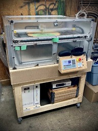
Here it is as it sits now (Dec 02, 2019). Ran out of M5-8mm screws. More on Wednesday.
It's a work in progress and a lot of it I'm making it up as I go. Many parts have been reclaimed from a C-Beam MachineXL that I no longer needed and disassembled. I will try my best to upload photos and descriptions as I go.
Cheers
I took Pedro's advice and setup the X/Y gantry on it's own to check clearances and work out bugs, rather than waiting until it's installed into the frame. Good advice. Here's a motion video.
Note: Not sure why it's over-scanning so much. I just downloaded a couple RDWorks test files from the BOSS Laser site.
Also, I had to give the laser tube and PSU a functionality test. I bought it from CloudRay via AliExpress. You only have a certain amount of time to get a replacement in case you get a dud. Here's that video. (Forgive the babble at the end. I was pretty excited to fire my first ever laser... lol)
Note: I am aware that there is no cooling system in place, however, it was just a short 200ms pulse, and the only one fired. The next time it fires, it will be cooled.
The first version of the laser head mount was 3d printed in ABS. Entirely not ridged enough due to the thickness.
So ... I found a 4.5mm piece of scrap plexi that a friend gave to me years ago and cut it on my CNC machine.
These pieces here are cut from Pedro's files. There might be a few adjustments here and there.
This pic here is me trying to come up with an idea for mounting the tube. I forgot to order a tube holder from CloudRay and wasn't sure I wanted to 3D print one. So I came up with this. The clamp will be lined with 4mm foam to even out the pressure a bit. Obviously they will be mounted facing each other as this pic was just for rough fit and visualization.
![[IMG]](https://openbuilds.com/attachments/20191126_212737-jpg.43490/)
45W CO2 Laser Build
Build in 'Laser Cutter Builds' published by wackocrash5150, Jun 10, 2021.
A co2 laser build that is heavily inspired and based quite a bit off Pedro Fernandez' 50w co2 laser build. This is my first build post so, bare with me.
-
-
Build Author wackocrash5150, Find all builds by wackocrash5150
-
- Loading...
-
Build Details
- Build License:
-
- CC - Attribution - CC BY
Inspired by
pedrofernandez' Openbuilds Table Top 50w Co2 Laser Cutter/Engraver


