How To Make a 32 Button Hand Pendant for the PlanetCNC Control Board
Using a Single Input Pin On an Arduino Leonardo
This project is something that I have been thinking about for a long time after I got the Do-It-Yourself version of a basic Planet-CNC control board to try out on my Sherline tabletop mill, and it works quite well. After I saw a YouTube video about how to use a hand pendant with the Planet CNC boards, I thought it would be a perfect addition to the mill and my next project. By the way, there are still plans, firmware and software available on the Planet CNC website that you could use to build your own DIY version of the board ( DIY - Planet CNC ). Recently I acquired a heavy duty 4’ x4’ gantry style machine from a factory closing sale. It does not have any drives on it or lifter so this contest is perfect motivation to work on the hand pendent project for basic machine operation. This presumes that I actually win, but hey, if you want positive things to happen, you have to think positive.
Now to the project at hand. The Planet-CNC software (version 2.10 is what this was tested on), like most software, allows you to click icons on the computer screen to use various functions in the program. There is an additional interesting feature in the Planet-CNC software that allows you to type a command from the keyboard into a window on the screen and the control board will respond the same as clicking the icon. For example, if you have homing switches installed and you want the machine to automatically reference to the home position you can either use the mouse to click the icon on the screen or you can type the /430 command in the MDI (Manual Data Input) window and the machine will begin the homing sequence. If you want to stop the program that is running you can click on the Stop icon or type /406 in the MDI window. There are over a hundred different commands that can be typed into the MDI window. Now clicking the icon with a mouse pointer would be easier than typing the commands into the MDI window, especially if you are wearing work gloves, but there is actually a third option that is much easier than the first two. There is a way to make your own remote pendent do the typing of multiple characters for you with just a press of a single button so you don’t have to search the screen for the correct icon or try to type anything into the MDI window. Luckily there are a lot of people that are in the spirit of open source sharing of information and I stumbled across a YouTube video (just search for "custom USB keyboard to control G0704 mill using Planet-CNC.com controller") that showed how to do a different version of what I will show below. Using a version of an Arduino called the “Teensy” (Teensy USB Development Board) and the Arduino keyboard function Rich built a homemade pendent with some buttons to communicate with the MDI window on the computer that the Planet-CNC board is running on. While Rich’s version only uses 8 inputs, it does everything he wanted with some I/O pins left over for future expansion.
I wanted to try something a little different, partly because the “Mad Scientist” part of me just wanted to see if I could get it to work and mostly because I wanted it to handle more inputs and do more things. The typical method would be to have an input pin for each button so the number of commands that could be used would be equal to the number of input pins. My method uses only one input pin for up to 32 command buttons. While working on this I found that it would take 16 buttons just to do all of the axis jogging features that are available. The remaining 16 buttons will do other functions such as setting the zero position, start the homing cycle, etc. The way to do this is relatively simple using a voltage divider network that uses 32 resistors, 32 buttons and one analog input. By the way, if you build your own version of this you are not locked into 32 buttons, I will explain later how to increase or decrease the number of buttons. The resistors are connected end to end to form the network, then one side of a normally open button is connected at the junction of 2 of the resistors and the other side of all the buttons are connected to a single analog input pin on the Arduino, see the wiring diagram below. During testing I found that if the analog input is left floating you will get random values over the full range of the 10 bit conversion. To get rid of that problem I put a 1 mega ohm resistor between ground and the input pin to pull the input to zero when none of the buttons are pushed. To minimize the effect of the noise resistor on the value of the network, which would be in parallel with the R2 side of the resistor network, a high value resistor is best. In order to find out what the analog to digital value would be, I made a spreadsheet to do the calculations. The value for the resistors used in the network is not real critical, I used 680 ohms and pretty much any value will work as long as the resistors are all the same value. In the included spreadsheet you can put in different values for the resistors, Analog to Digital resolution and input voltage to see what different combinations of values will do. The most interesting thing that I found is that the precision rating of the resistor is the most critical factor in getting this to work correctly. If the digital value that was selected for the Arduino sketch was based on the 0% calculation and then 5% resistors were used it could potentially cause an overlap of the actual values when compared to the calculated values if you had one resistor that was -5% and the next one was +5%. This presumes that you just went with the marked values and did not measure the actual value of the resistors. After I made the first spread sheet I made another one that lets you enter in the actual measured values for each resistor.
Below is a screen shot of the spreadsheet that I made to calculate the values. (this is my first post here and I could not figure out how to embed the screen shot so refer to attached files) My first breadboard prototype only has 16 switches and with 0.1% resistors there is no overlap in the values along with about a 60 point window. In the circuit that I built later I used 1% resistors and all of the serial monitor reported values were within 2 points of the calculated 0% value.
In the next screen shot you can see the effect of +/- 5% resistors, a few switches have an overlap that may affect which signal gets sent to the board. Again, this presumes you did not measure the actual resistor values. The first spreadsheet tab uses the same value for all the resistors. There is a second tab in the spreadsheet that allows you to enter the actual measured values of the resistors you pull out of your junk box. The spreadsheet also has a macro that will kick out a text file with all the values ready to be copied and pasted into your Arduino Sketch which makes for easy updates.
I mentioned earlier that you are not locked into 32 buttons and you can see that I setup a bread board with a 16 button prototype. While testing I noticed that the digital value only varied about 3 points at most when any button was pushed, this is where the serial monitor feature came in handy so that the value for each button can be seen. At idle while waiting for a button press the noise value was about the same 3 point amount. A 16 button setup has about a 60 point window and a 32 button setup has about a 30 point window. Just use the spreadsheet and enter the number of buttons you want and it will calculate the window value along with the “greater than” values in the Arduino sketch. If you were willing to have a 10 point window you could get 100 buttons to work. The spreadsheet is currently only setup for a maximum of 32 buttons but you can just copy and paste the formulas to get more buttons. Page protection is turned on but there is not any password so you can unlock it easily. If you add buttons to this, you will need to unhide column “A” and you will have to do a lot of manual editing to keep the Macro working with the extra buttons.
Now here is the advantage of doing it this way, you now have a bunch of I/O pins on the Arduino available for other things. Right now I was only interested in getting the functions for the Planet CNC software to work but you could modify the code used here to use one of the buttons to turn something on or off, like a relay that controls the motor on your dust collector. Maybe have one button that turns the shop stereo system on and off. You could use one as an input for when the phone rings to turn off the stereo and pause the program on the machine. I am sure you get the idea, the possibilities are endless.
Now getting back to the Planet CNC software, also linked to the MDI feature in the Planet CNC software is the ability to setup hotkey combinations that do the same thing as clicking on the icon or typing commands in the MDI window. In the screenshot below you can see the first of three jogging set commands. Even though this window shows axis A, B, C etc. it is actually axis X, Y, and Z, not sure why it was labeled this way. The default setup for jogging the X axis to the left is to hold down the right hand “CTRL” key and pressing the left arrow button. This can be edited to any key combination you want. There are some commands that have a four key combination by default. So this makes it possible to edit this set or use one of the other two sets that are available to create your own custom combination set with any combinations you want. For the functions I want to setup I decided on a two key combination that uses the F12 key and the letter keys “a” to “z” and numbers 0 to 5 for a total of the 32 combinations that could be used.
In the screenshot you can see that the setup for defining the hot key combinations allows you to press a keyboard button and the program will show you the key code numbers. I thought that I could just use the same codes as the standard ASCII codes but those don’t include the Function keys. So I tried using the same number that showed up in the “test key” window thinking that would work but this is where something unexpected happened. On the screen you can see that the ASCII key code for the uppercase letter “D” shows up correctly as 68 and the F12 key is showing as 123 which is correct for some systems based on a google search for that topic. The problem that I ran into was when I sent 123 from the Arduino the key code for the open bracket symbol “{“ is sent along with a left shift key command which is the correct ASCII code combination for the bracket symbol. If I send a 68 from the Arduino the test key window shows a Left Shift “160 + 68”. To get just the upper case “D” the Arduino has to send ASCII code 100 for a lower case “d” then the Planet CNC window shows code 68 by itself. So the work around to solve this problem is to use the lower case codes in the Arduino software and the upper case codes in the Planet CNC software. Now for the F12 key code; in order to find out what code is used for the F12 key a second program was written to increment the key code by one at a time using a normally open switch between ground and pin 2 on the Arduino, and send the code to the test key window and the Arduino serial monitor at the same time. This showed that the Arduino has to send code 205 to get the F12 key command in the Planet CNC software where it is recognized as 123. This “key test” program will be included in the files section if you want to try it yourself. I also included the list of codes in the spreadsheet with the resistor calculations. Although there is something strange going on here, and I think it has to do with how the Planet CNC software recognizes the code sent from the Arduino or the keyboard, the work around is simple enough that I don’t plan to pursue finding the cause of the problem because I don’t think I could do anything about it anyway. When you go to setup the hotkey combinations in the Planet CNC software just have the pendant hooked up and press the button you want for each function you want to use and let it record whatever shows up and click the set button.
Now before I get into the Arduino sketch I want you to know that this is my first attempt at writing an actual useful Arduino program, previous to this I did the standard “blink the LED” programs. There is no doubt in my mind that someone out there with more experience could improve upon this code but I will say that this code works and does EXACTLY what I wanted it to do. I also put a lot of comments in so that it is easy to understand what I am try to accomplish. Anyone that wants to revise this and make a “high speed, low drag” version of this is welcome to do so. I actually encourage it and I would like to see other versions, with lots of notes, so that I can learn better ways of writing code.
So here we go, since getting the EXACT digital value needed would be wishful thinking, the decision was made to use a range value that puts the ideal value smack dab in the middle of the range. The simplest way that could be found was to use a maximum value and to use a command of “IF value X is greater than value Y THEN GOTO next section else do the code in this section”. If the value of X is still greater than the value of Y for next section then GOTO the next section after that and so on down the line until it hits the correct section.
Here are just a few sections of the code to show how this will work. The serial function is only needed for testing and troubleshooting. Any line that starts with "Serial" can be commented out since it is not needed for the program to perform its designated task. The easiest way found to comment out all of the serial commands at once is to go to the edit feature and run a find and replace. Set find to "Serial." and set replace with to "//Serial." and that will comment out all the serial lines but still allow you to re-enable them later by just reversing the "find" and "replace with". I have found the serial monitor to be a useful tool so just left the code in there.
While researching this I found that several sources recommended being careful with the keyboard function because if you get it caught in a loop it will render your computer keyboard unusable as long as the Arduino was plugged in to the same computer. It could be very difficult to get it to stop running the loop which could effectively “brick” the Arduino. Originally I planned on turning the keyboard function on at the beginning of each section and off at the end of the section. Then I saw an example on the Arduino web site that used a second input pin and a line of code that only enabled the code if an input pin was pulled to ground. This led to the idea of a “dead man switch” that would enable the code only when the DMS was held down. This would prevent any accidental button press on the pendent from doing something you didn’t want to happen. Since I had already written each section with the keyboard start and end commands I just left them there as a safety net. Probably don’t really need them now but they don’t hurt anything either.
The first 16 buttons are dedicated to the jogging functions for X, Y and Z axis, so they were made capable of being held down to jog the machine. In the software, Buttons 1 through 6 use a different repeat structure than buttons 7 through 16, this is to allow single stepping the motor while holding the button down. There is enough time between steps to release the button before the next step is commanded for easier positioning of the machine. The Button1 code is equivalent to holding the F12 key and tapping the letter “a” key every 500 milliseconds so the axis will move one step at a time. The timer value for the delay between steps can be changed to whatever you prefer.
WhichButton = analogRead(Button); //read analog input value and convert to digital value
Button1: // Move X axis positive direction one step at a time
if
(WhichButton > Value1) goto Button2; // if Value1 is more than the maximum for this function
// goto next button else do this function
Serial.print(" button 1 "); // text output to the Arduino serial monitor screen for testing
Serial.println(WhichButton); // shows current value of analog to digital conversion. Values are NOT passed to
// keyboard. This section was used for testing and troubleshooting
// and is not necessary for program to function so it can be commented out if you want.
Keyboard.begin(); // turn on keyboard function
Keyboard.press(F12); // equivalent to press and hold key F12
Keyboard.press(Button1); // Equivalent to press and hold key assigned to variable "button01"
Keyboard.releaseAll(); // Release all key functions that are active
Keyboard.end(); // turn off keyboard function
delay(StepDelay); // delay timer so you can hold down the button for "single step" to move motors one
// step at a time and still have enough time to release button before next step is
// commanded, timer value can be changed to your preference.
Repeat = analogRead(Button); // read analog input to check if button is still being held
If (Repeat<Value1 && Repeat>Value00) goto Button1; // if button is still being held, repeat button code to // move motor another step
// else go back to start.
goto Start; // goto to start of program and monitor buttons
Buttons 7 through 16 will move the machine continuously while the button is held down. The major difference in this code is that the Keyboard.press function is turned on and left on while the loop function just checks for the release of the button. When the button is released it jumps out of the loop to release the keys. This allows for smooth continuous motion while the button is held down.
Button7:
if
(WhichButton > Value7) goto Button8;
Serial.print(" button 7 ");
Serial.println(WhichButton);
Keyboard.begin(); // turn on keyboard function
Keyboard.press(F12); // equivalent to press and hold key F12
Keyboard.press(Button7); // Equivalent to press and hold key assigned to variable "Button7"
Loop7:
delay(DeBounce); // delay timer to allow for switch debouncing after the release of the button
Repeat = analogRead(Button); // read analog pin to check if button is still being held down
if(Repeat<Value7 && Repeat>Value6) goto Loop7; // Check to see if button has been released.
// If button is still being held then repeat button
// check loop. When button is released, continue code
// to release keys. Machine will move continuously as long as
// button is held down.
Keyboard.releaseAll(); // Release all key functions that are active
Keyboard.end(); // Turn off Keyboard function
goto Start; // return to program start and monitor buttons
Buttons 17 through 32 will be used for other functions such as starting the homing sequence, setting the X0 and Y0 positions, etc. The major difference between these buttons and the others is that there is no repeat loop, the code runs one time and then jumps back to the “IsButtonStillPushed” loop that checks to see if the button is still being held and will stay in that loop until the button is released. This is to prevent the command from being repeated if you hold the button down.
Button17:
if (WhichButton > Value17) goto Button18;
Serial.print("button 17 ");
Serial.println(WhichButton);
StuckButton = " Button 17"; // Variable used for detecting if a button is stuck. Value is changed in
// each button section of code. Message is sent to serial monitor only,
// these lines can be commented out if serial monitor function is not used.
Keyboard.begin(); // turn on keyboard function
Keyboard.press(F12); // equivalent to press and hold key F12
Keyboard.press(Button17); // Equivalent to press and hold key assigned to variable "button17"
Keyboard.releaseAll(); // Release all key functions that are active
Keyboard.end(); // turn off keyboard function
goto IsButtonStillPushed; // goto loop to test if button is being held
The next section of code is the “IsButtonStillPushed” loop for checking for the release of buttons 17 to 32. Since the code for these buttons only needs to run once this loop prevents repeating the command by staying in this loop until the button is released then goes back to the start of the program.
IsButtonStillPushed: //if button is being held down this loop prevents the command from being repeated.
//The Button has to be released to go back to start of program.
// Only used on buttons 17 to 32
delay(WaitForRelease); //timer to allow for releasing button.
// Adjust the value to your liking in constants section above
StillPushed = analogRead(Button); //get voltage reading of button
if (StillPushed < Value00) goto Start; // check digital value and compare to noise level constant
// to see if button has been released
else
{
String string2 = " is stuck. The analog to digital value is "; // A message that shows in the serial monitor window
String string3 = StuckButton + string2 + StillPushed; // if serial function is turned on. These lines
Serial.println(string3); // can be commented out if serial function is not being used.
delay(WaitForRelease); // reuse the delay timer to allow some more time for releasing button.
// Adjust the value in constants above to your liking.
goto IsButtonStillPushed; // go back to start of loop to recheck if button has been released.
}
The wiring diagram is pretty simple and just look at all those unused I/O pins just waiting for something to do. The button circuit and the Arduino is powered through the USB connection to the computer. Not all Arduino boards can use the keyboard function. Boards that use the 32u4 or SAMD chip such as the Leonardo, Esplora, Zero, Due and MKR boards can use the keyboard function which is needed for all of this to work.
I decided to make a shield PCB board for the resistor network and for the connection to the Arduino when I came up with the idea to use 2 separate boards. One board will be for the resistor network and buttons and the other will be an interface “shield” that mounts on the Arduino board and they are connected to each other using a standard Ethernet cable that are easy to get and in a variety of lengths. This would allow the Arduino board to be mounted near the computer and the pendant would have the resistor network and buttons. This is where I made a major blunder when I was laying out the board in the Express PCB software. The circuit was simple enough and I didn’t have a lot of time to work on it that I went right to the board layout without drawing a schematic. The plan was to use a 40 pin IDE hard drive cable to connect between the buttons and the resistor board. When I drew it up I put the 5 volt supply and ground on the wrong ends of the resistor network so when I plugged it in none of the buttons were doing what I expected. With this mistake I had to decide whether or not to get new boards made, unsolder all the wires and rearrange them, or edit the software. New boards meant more money and all those little wires were a pain to solder to begin with so the idea of redoing all of that did not thrill me, so I just moved the blocks of code around to match the function that I wanted with the button I wanted to use. This is where the serial monitor code really paid off because I could easily identify which button was being recognized. The Arduino code I included on the Open Builds site is the original code and the Express PCB board file that I included has been fixed so if you decide to use it you should not have to change anything but if something goes wrong you know that you can just rearrange the code to get it to work.
When I was making the video I found that there was a lot more noise on the signal when everything was hooked up to the mill I was using. I was able to adjust the noise filter level in the software from 10 to 25 but if there is more noise when the spindle is running I may have to add a noise filter to the circuit.
The case I used was 3D printed and will just barely fit on a machine with 200 mm print area and the STL file will be included. I have the box on TinkerCad as 2 separate parts, the button panel and the box. Still learning TinkerCad and I did share the 2 files on Thingverse, just search for “Planet-CNC pendant button panel” and “Planet-CNC pendant Button panel box”. You can modify this for your application if you want. On the button panel all of the text is raised 1 mm, I think it might be better to make the text a 1 mm recess instead. The text was the last thing to be grouped together to make changing it easier.
The Planet-CNC software version 2.10 is what this was tested on. I have not tried the new version that is posted on the Planet-CNC website but I think it has the same features used here.
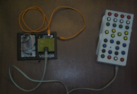
As you can see, it can be very useful to have a hand pendant with buttons dedicated to certain commonly used functions on pretty much any machine. This allows for very easy operation of the machine without having to fuss with the computer keyboard and mouse. All of the unused inputs and outputs can now be setup for any other functions you can think of for your application. Now I just have to figure out how to make this battery powered and wireless.
Also, I am not going to be bashful about this. You have to admit this is a good idea so vote for me, I can put that prize package to good use on that 4’ x 4’ machine I picked up at the factory closing!!!
Thanks for reading all of this and I hope you can use this idea for one of your projects.
32 Button Hand Pendant for the PlanetCNC Control Board
Build in 'Circuit - Software Project' published by Cheeze, Feb 24, 2018.
This project is for building a remote hand pendant for the Planet-CNC control board but could be adapted for many other projects. The pendant allows for machine control without being at the computer keyboard and the button functions on the pendant are defined by the user.
-
-
Build Author Cheeze, Find all builds by Cheeze
-
- Loading...
-
Build Details
- Build License:
-
- CC - Attribution NonCommercial - Share Alike - CC BY NC SA
Reason for this Build
Just to see if I could get it to work and to use on a large router table to be able to jog, start, stop, tool change the machine without having to walk back and forth to use the computer keyboard.Inspired by
Rich Lowen's pendant for his mill -
Parts list
Qty Part Name Part Link Comments 1 Arduino Leonardo Link 32 normally open momentary contact switch Link 1 standard network cable Link any length you prefer 1 Express PCB resistor network board / shield board Link Board file included. One board has both sections and is cut in half 1 hand pendant box Link build your own or use STL files included 1 40 pin IDE hard drive cable Link time to dig into that box of stuff you knew you would use someday 1 40 pin IDE socket for PCB board Link 32 680 ohm resistors 1/8 watt Link does not have to be 680 ohms but all need to be same value 1 1 Mega ohm resistor 1/4 watt or 1/8 watt Link 2 RJ-45 board mount socket for PCB board Link 6 0.100 head pin connectors Link for mounting the shield to the Arduino -
Attached Files:
![[IMG]](proxy.php?image=http%3A%2F%2FD%3A%5Carduino-1.8.5%5CPortable%5Csketchbook%5CPlanetCNC-Keyboard-Leonardo-32%5Cscreen+shot+1.jpg&hash=8f249cda3214a2e057c756513e84b512)
![[IMG]](proxy.php?image=http%3A%2F%2Ffile%3A%2F%2F%2FC%3A%2FUsers%2FTom%2FAppData%2FLocal%2FTemp%2Fmsohtmlclip1%2F01%2Fclip_image002.jpg&hash=46de51283aad67190c7c6af95d58bea0)
![[IMG]](https://openbuilds.com/file:///C:/Users/Tom/AppData/Local/Temp/msohtmlclip1/01/clip_image004.jpg)
![[IMG]](proxy.php?image=http%3A%2F%2FD%3A%5Carduino-1.8.5%5CPortable%5Csketchbook%5CPlanetCNC-Keyboard-Leonardo-32%5Cscreen+shot+2.jpg&hash=97fdd2ac6d0412c15561499c2ad7eb68)
![[IMG]](https://openbuilds.com/file:///C:/Users/Tom/AppData/Local/Temp/msohtmlclip1/01/clip_image006.jpg)
![[IMG]](proxy.php?image=http%3A%2F%2FD%3A%5Carduino-1.8.5%5CPortable%5Csketchbook%5CPlanetCNC-Keyboard-Leonardo-32%5Cscreen+shot+3.jpg&hash=c3b984e374f023cc4fc07bcfe0b3c7fb)
![[IMG]](proxy.php?image=http%3A%2F%2FD%3A%5Carduino-1.8.5%5CPortable%5Csketchbook%5CPlanetCNC-Keyboard-Leonardo-32%5CWiring+Diagram.jpg&hash=72190df785dbdc226564e074c5001b6d)


