
Details:
Lead screw whip:
My stock 1515 was not one with the longer lead screws & tension assembly method. It whipped. I designed a simple add-on plate that attached to & sat just behind the existing end plate. It let me move the bearing and nut back with enough room to adjust & tension the lead screw.
Gantry twist:
I joined (2) C-beams back to back.They're mechanically fastened with a series of 8-32 socket cap screws & spacers. The 8-32 spacers are .250" diameter & register nicely in the slots of the extrusion - they're what kept the beams aligned during assembly. Strips of 3M VHB tape further bond the rails.
X rails:
I mounted 15mm rails on the top and bottom of the gantry beam. I drilled & tapped the extrusion to mount the rails.
Gantry cart:
(4) HGH15 bearing blocks are mounted via brackets to a 3/8" aluminum plate. The top bracket is fixed & the bottom is slotted so I could let the rails set the position before locking everything down.
The whole Z axis attaches to (4) studs on the cart. Easy on, easy off... easy maintenance.
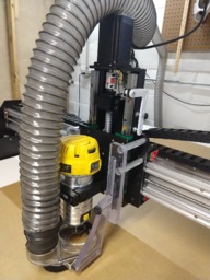
Z axis:
1/4" aluminum plate; 15mm rails. 16mm x 250mm ballscrew. Pretty typical, except that I kept everything as compact & light as I could.
I decided to wait until this was built to decide where & how I'd mount my limit switches. I ended up adding a bracket to the side (white in the picture). I had planned for a 2nd limit switch on the bottom & still might add it but haven't felt that it's necessary yet.
Router mounting:
Behind the standard Openbuilds router bracket is a plate with eccentric nuts that'll allow me to tram the router from side to side. The plate includes holes to attach a second router bracket if I decide that the single bracket isn't stiff enough (so far, it is).
Dust collection:
I designed it to accept the Suckit Dust Boot, which in my opinion is the best dust boot on the market. It's Z axis independent, so it stays in contact with the work surface & doesn't raise & lower with the router. it's also easy to take on & off & lets you see the end mill while cutting.
Small details:
- I redesigned the gantry end plates to minimize leverage from the heavier Z axis.
- The inner gantry end plates are shortened slightly to allow the Z axis to pass over them, slightly increasing usable space.
- The front (Y axis) end plates are redesigned to get rid of extra metal & unused mounting holes. I also included open ended slots to make servicing the lead screws easier.
![[IMG]](proxy.php?image=https%3A%2F%2Fi.ibb.co%2FmyzsNtS%2Fgantry-end-plate.jpg&hash=cb97e70b998520175e35eb7864159547)
1515 Deluxe
Build in 'Cartesian Style CNC' published by brrian, Apr 18, 2020.
Build features include a double c-beam gantry (bonded & mechanically fastened), linear x rails, custom gantry end plates, a custom linear rail & ballscrew Z axis, and custom lead screw tensioning plates. The primary goal was to remove twist from the 1500mm gantry & stiffen the Z axis.
-
-
Build Author brrian, Find all builds by brrian
-
- Loading...
-
Build Details
- Build License:
-
- CC - Attribution - CC BY
Reason for this Build
I moved from a Shapeoko XXL to a Workbee 1515, to gain cutting area. The increased size meant more twist & flex in the gantry (compared to the Shapeoko) and my goal was to improve that & to at least match the capability of the Shapeoko. -
Attached Files:
![[IMG]](proxy.php?image=https%3A%2F%2Fi.ibb.co%2FkqXpkxg%2Fy-end-plate.jpg&hash=746fe4988924c6b39ab445087b56f015)
![[IMG]](proxy.php?image=https%3A%2F%2Fi.ibb.co%2Fx8HVxjm%2Fcart-top.jpg&hash=ac4cddf9018cbde780433babbc9e98a8)
![[IMG]](proxy.php?image=https%3A%2F%2Fi.ibb.co%2Fcb6Z5xw%2Fcart-front.jpg&hash=2f6c5d2bc252c36705778c5999b0d2c3)
![[IMG]](proxy.php?image=https%3A%2F%2Fi.ibb.co%2FJzxr1gx%2Fz-axis-1.jpg&hash=c669dc352bec2fdb29917aea89e3fc4b)
![[IMG]](proxy.php?image=https%3A%2F%2Fi.ibb.co%2FQcF1rSg%2Fz-axis-assembled.jpg&hash=ddc6631259b29b45ee71f9963a3b8022)