
Just another Workbee 1510 CNC, with some tweeks!
12/5/2018 Linear Bearing Blocks
-Added Annotated Drawing
-Added Inventor Files
-Added CAM .step Files
12/15/2018
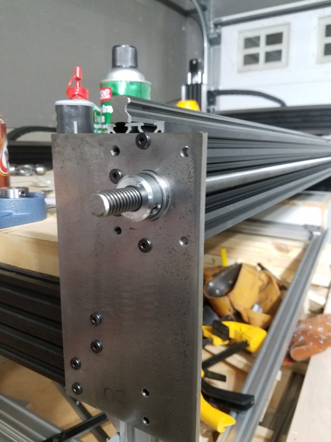
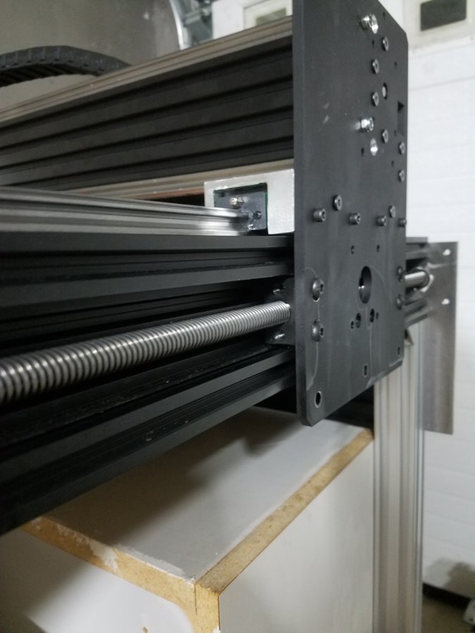
Progression of Lead Screw installation
-Machined 1.125 counterbore to accept bearings
-installed nut blocks in gantry plates.
1/10/18
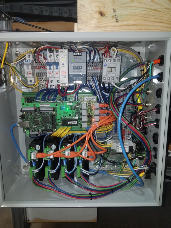
Electrical Enclosure Assembly
- Wired internal Enclosure
- Waiting on missing parts from CNC4PC
- Interface with outside Components.
See progress on my new thread ESS Control system.
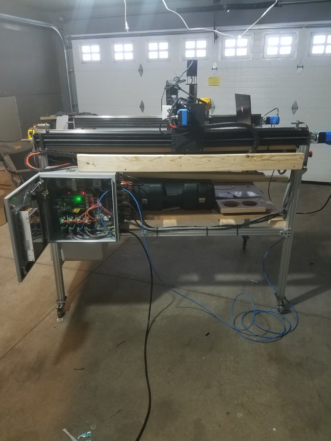
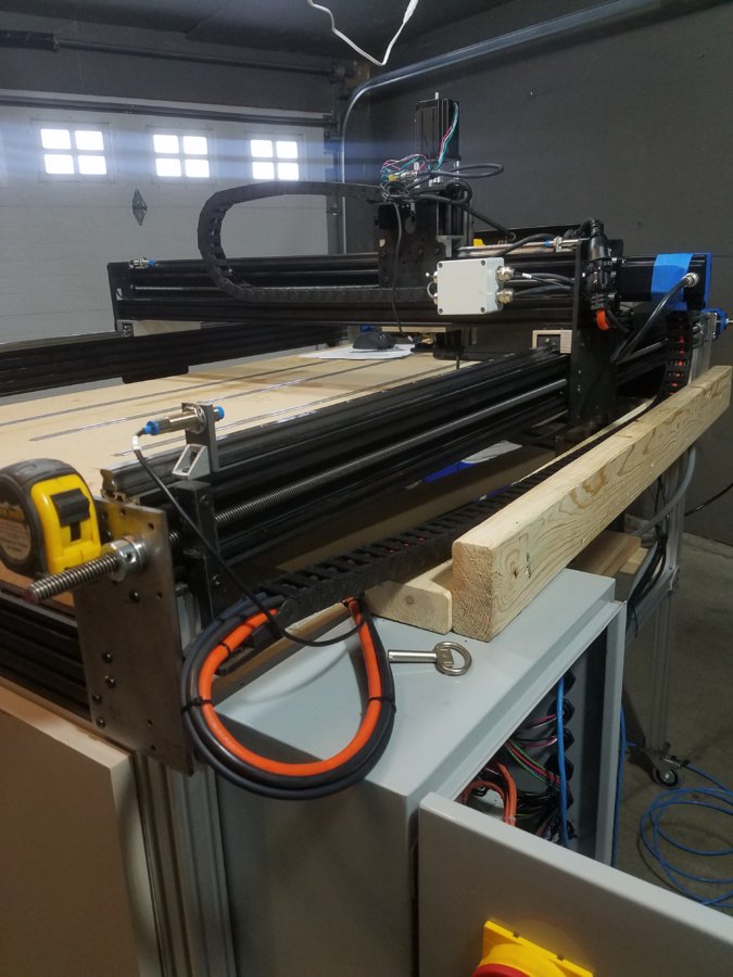
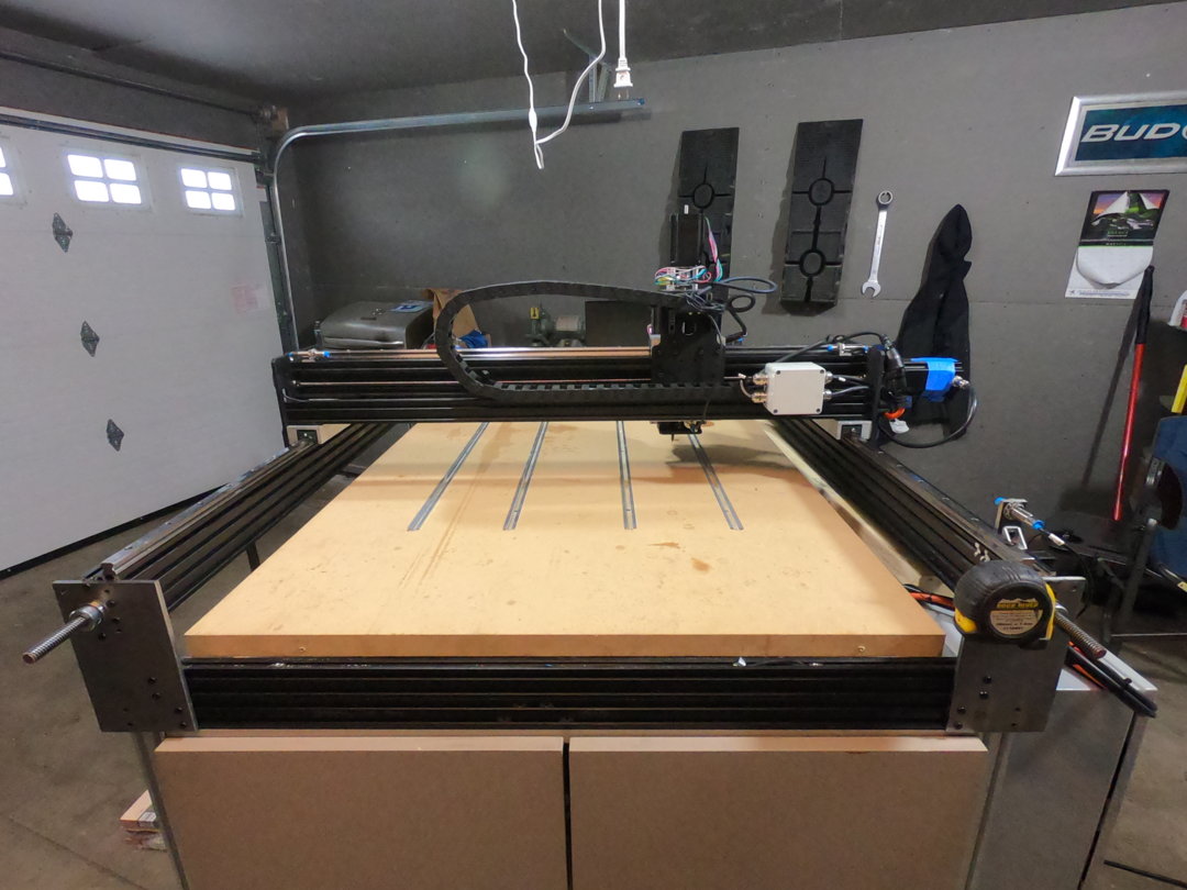
1. I wanted to raise the entire y-axis c beam rails 2 inches to give me a total of 3 inches of travel with the z axis. Have found 0 issues with doing this as the machine is still stable.
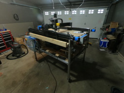
2. I wanted to make the CNC mobile because I do enjoy cutting outside. It also makes it easier to work on when I have the ability to pull it away from the wall. I cut and machined out some square stock to bolt to the aluminum extrusion and then to the casters.
![20181104_184757[1].jpg](data/attachments/36/36298-ecb5b2eaa3a1c77acdd4b0d6f8556f94.jpg)
![20181104_184250[1].jpg](data/attachments/36/36301-390c23e7d6e453454984ff92a51ae258.jpg)
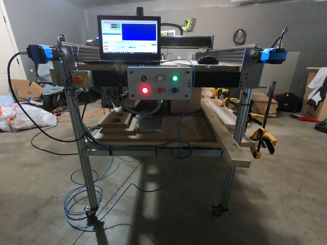
3. I used a button enclosure that I have had laying around from a past Corrugator installation job and used that to hardwire the buttons, Power (Red Pilot), Resume (Green), Pause (Blue), Stop (Red Extruded), Keyswitch which enables power to the machine, and a Spindle on which gets sealed in via Motor Contactor and breaks the seal with the Stop PB. All buttons are pilot lit to indicate which buttons can be activated, or running operations. Disregard the Button Names as this was pulled off a machine called a Doublebacker.
![20181202_110505[1].jpg](https://openbuilds.com/attachments/20181202_110505-1-jpg.36326/)
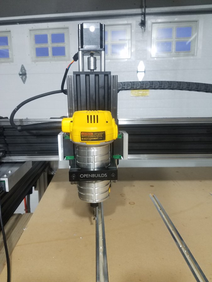
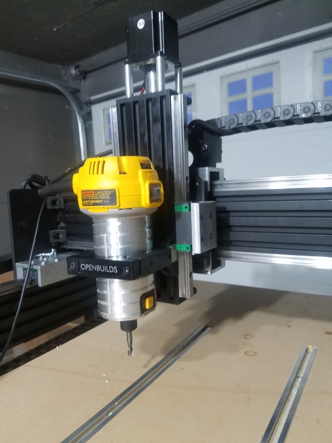
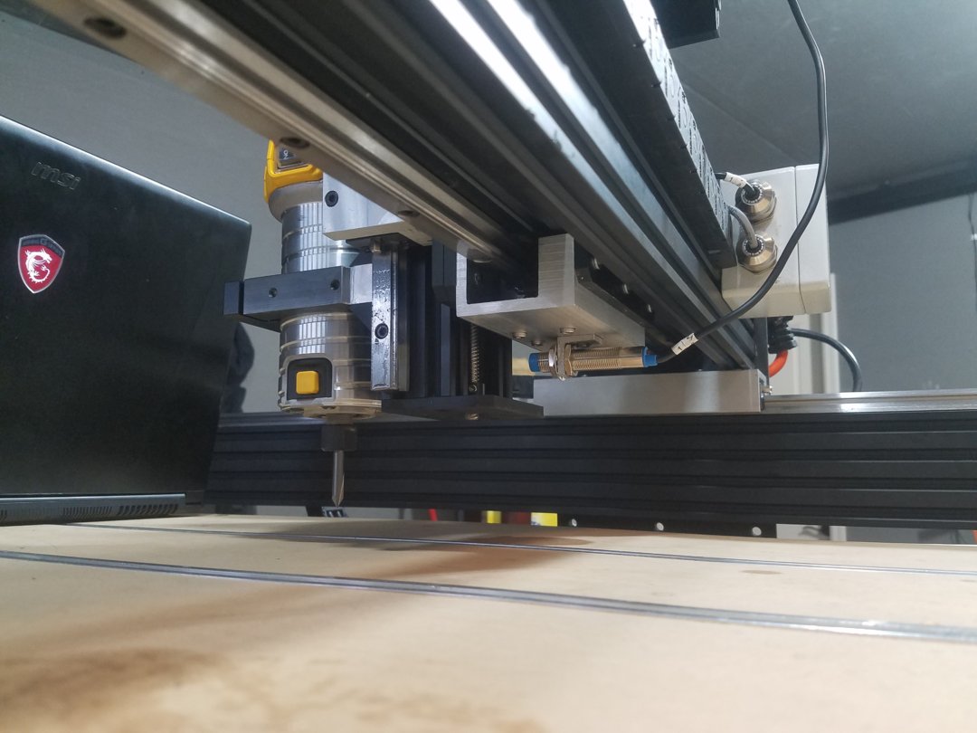
4. If you find those v wheels as frustrating as I did with, twisting, inconsistent tension, and a messy disassembly than this is for you! I was fed up with the way the gantries would twist given a heavy load that favored one side more than the other. On top of that the excessive amount of lash the z axis gantry had when slightly pulling on the router. In search of a solution I found no better way than to use Lineal bearings.
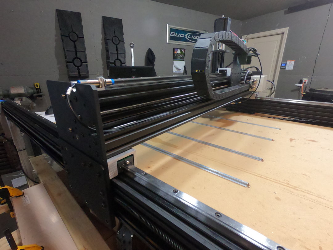
When installing the Lineal Bearings I found so many benefits! The gantries slide with ease and have little to no twisting with a span of 1000mm. They added rigidity to the already rigid c-beam extrusion, but there can never be enough. These Lineal Bearing give you the ability to level your gantries to the table, buy a simple tramming tool and run it across your table. When Low spots are found, place shims underneath the lineal rail whether it be the x or y gantry. No more surfacing spoil-boards! Should always have a true table, and a spoil board over that to cut into anyways. Sure, this may be overkill, but precision should always be key. My favorite part of these, is the ease of disassembly of the gantries. Take off 6 bolts on one side and the bearing can glide away and the x axis can be taken out. Need to take off the z-axis? Now the y-axis gantry plate is tapped to easily removal the z-axis. I think we all know those pesky bolts that were impossible to get to with the x-axis gantry still in the machine. To reassure proper alignment all the plates are pinned, so once shims are in, there is no need to take them out again.
![20181201_220720[1].jpg](https://openbuilds.com/attachments/20181201_220720-1-jpg.36322/)
![20181201_143126[1].jpg](https://openbuilds.com/attachments/20181201_143126-1-jpg.36323/)
![20181201_220705[1].jpg](https://openbuilds.com/attachments/20181201_220705-1-jpg.36324/)
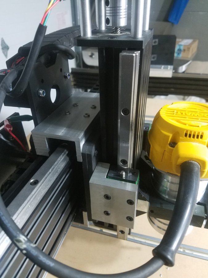
This is all fine and dandy if you have access to the right equipment as I did use a vertical mill to make the blocks that mount to the bearings and gantry. But I would still love to see openbuilds provide an option like this, as it is not too much more expensive to have a system like this. at 140 dollars a pair of 1500mm long rails (I bought 2 pair) and stock of aluminum, I got a 2x3" 46" long for 75 dollars. I think for 355 dollars, this was a worth while upgrade.
I am still in process of mounting the z axis lineal rails, but will be done with coming week as I need to machine out more mounting blocks.
update 12/4/2018
Just finished the peices to mount the Bearing blocks. Works very well and makes the axis much more stable under load. I am very happy with the results!
update 12/15/2018
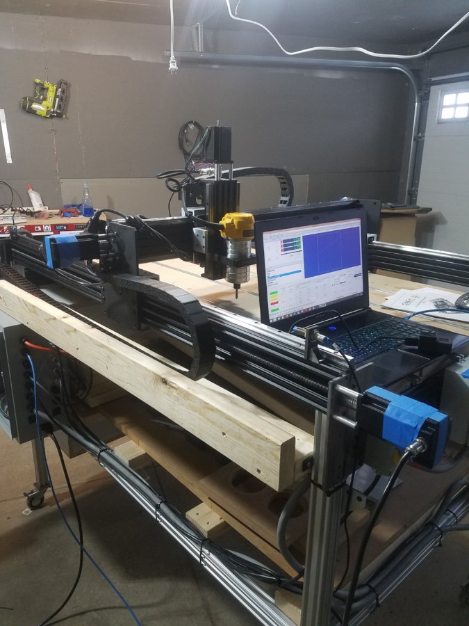
Update 11/22/2019
waiting on motor cover for Z axis as well as all the bolts for covers, hence the blue Tape
Here is the Final Pictures for now as everything is up and running. If anyone has questions on the Control System go to my Other Page called CNC ESS Controls System and discuss there. This is a purely mechanical Page.
Thanks for Looking at my build!!
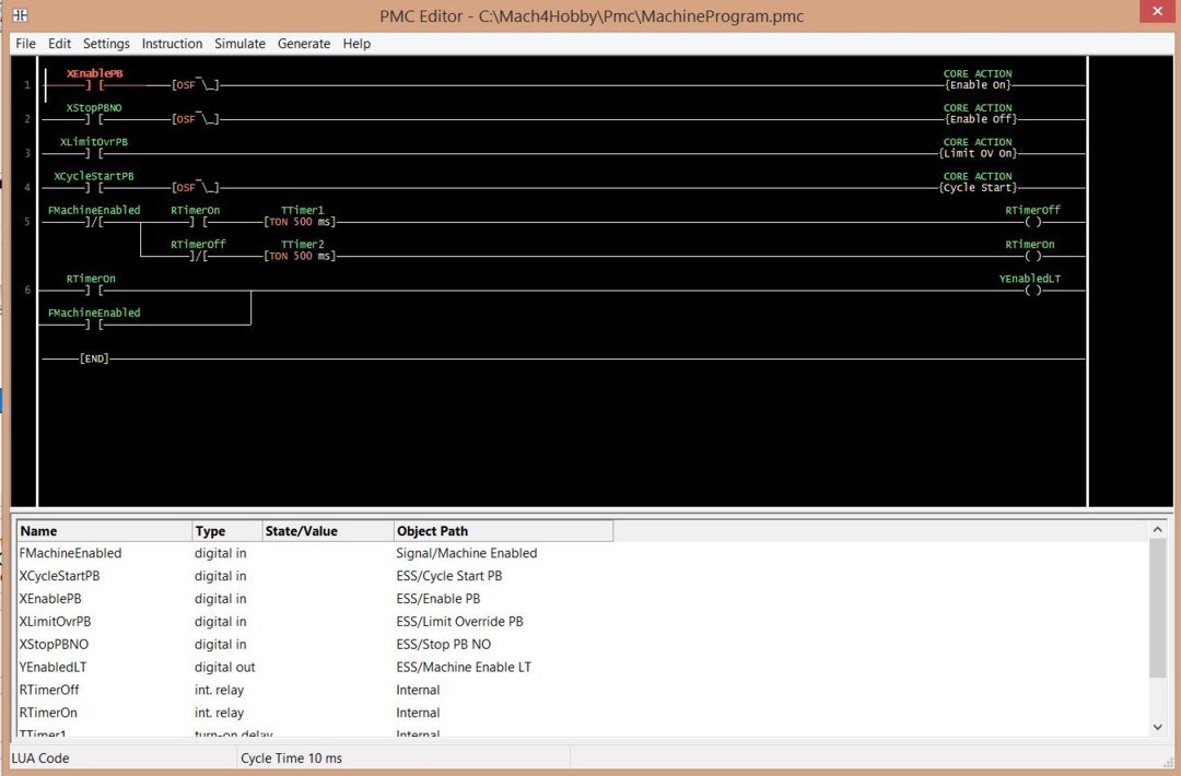
Installed the Ops console back on and Configured it through the PMC editor in Mach4.
1. What It does is when the machine is not Enabled, the Green Light will flash every 500ms.
2. When the enable button is Pressed The machine will enable and the light will go Solid green. The machine enabled output contact will be placed before the Flashing Rung to disable it when the machine is enabled.
3. When g-code is loaded, Pressing the White button will Start the Cycle. When a Cycle is active the White light will be ON
4. Pressing and holding the Blue button will override the Limits and the Light will be turned on indicating that the Override is on, even when pressing it in the Mach4 Program
5. Pressing the Red Fstop button will disable the machine, which also performs a cycle stop.
6. The Red light indicated power present within the console.
7. The selector Switch Disables power to the Console for Service.
1510 Workbee Modified
Build in 'Cartesian Style CNC' published by Jacob Lotter, Jan 22, 2019.
Some of the things that I have done to my 1510 Workbee Installed Linear rails and bearing blocks with drawings. Installed Ops console Made conversion plates for extruded aluminum to casters Extended z axis travel by a couple inches with steel plates. As of now in the process of installing Lead screws across the 1500mm length.
-
-
Build Author Jacob Lotter, Find all builds by Jacob Lotter
-
- Loading...
-
Build Details
- Build License:
-
- CC - Creative Commons Public Domain (CCO 1+)
Reason for this Build
I built this for making my Custom speakers. I enjoy enclosure making as well as crossover design to make something truly unique.
I also built this to have the know-how to do it, because I plan on building an entire Controls system based of a Ethernet Smooth Board.Inspired by
I have not seen other Workbee's incorporate lineal bearings, so I figured I'd give it a shot. -
Parts list
Qty Part Name Part Link Comments 2 Linear Rail 15-1500mm 2xLinear Guideway Rail https://www.amazon.com/gp/product/B072FRPGKP/ref=oh_aui_d... Link 2 M4 Slide in T Nut https://www.amazon.com/gp/product/B01GCDG2RI/ref=oh_aui_d... Link 1 (200) M4-0.7 x 15 MM Metric Allen Socket Head Cap https://www.amazon.com/gp/product/B078SB1JN1/ref=oh_aui_d... Link 1 2x3 inch 6061 aluminum stock Link Bought this cutoff peice at a local Metal Supermarket store. Found a peice at 43" length and charged 75 dollars. -
Attached Files:
-
![20181202_110505[1].jpg](data/attachments/36/36299-0338c7a6b2d971961c2c001a01ab60af.jpg)
![20181026_040009[1].jpg](data/attachments/36/36300-6ec19483614ea6ae5105a54f2459ce3c.jpg)
![20181201_143126[1].jpg](data/attachments/36/36302-369099232de77a6b7c52ae2cdf641403.jpg)
![20181201_220730[1].jpg](data/attachments/36/36303-aefb91f240d66eadb72a8f61e6b15462.jpg)
![20181201_220705[2].jpg](data/attachments/36/36304-9bc81a6b9348018fa24546f34f9eaab0.jpg)
![20181201_220730[1].jpg](data/attachments/36/36305-aefb91f240d66eadb72a8f61e6b15462.jpg)
![20181201_220730[2].jpg](data/attachments/36/36309-aefb91f240d66eadb72a8f61e6b15462.jpg)


![20181201_220730[1].jpg](data/attachments/36/36286-aefb91f240d66eadb72a8f61e6b15462.jpg)
![20181201_220720[1].jpg](data/attachments/36/36287-3281358f43a83f9105396349af07fb3f.jpg)
![20181201_143131[1].jpg](data/attachments/36/36288-01b47aa4b5535d9bc8a58fb8467fb435.jpg)
![20181201_132000[1].jpg](data/attachments/36/36289-6a9a9e23c2b30618fedd39ed2dc4aadc.jpg)
![20181201_143126[1].jpg](data/attachments/36/36290-369099232de77a6b7c52ae2cdf641403.jpg)
![20181129_201059[1].jpg](data/attachments/36/36291-ae6a65d90173258d1e382282694d4e64.jpg)
![20181201_220705[1].jpg](data/attachments/36/36292-9bc81a6b9348018fa24546f34f9eaab0.jpg)
![20181104_184250[1].jpg](data/attachments/36/36293-390c23e7d6e453454984ff92a51ae258.jpg)
![20181104_184757[1].jpg](data/attachments/36/36294-ecb5b2eaa3a1c77acdd4b0d6f8556f94.jpg)
![20181104_195217[1].jpg](data/attachments/36/36295-9ddae2bf43412dbb5eba642240d0d5ce.jpg)
![20181026_040009[1].jpg](data/attachments/36/36296-6ec19483614ea6ae5105a54f2459ce3c.jpg)
![20181202_110505[1].jpg](data/attachments/36/36297-0338c7a6b2d971961c2c001a01ab60af.jpg)