Welcome to Our Community

Some features disabled for guests. Register Today.

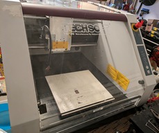
Techsoft Roland TS-30 rebuild

Discussion in 'CNC Mills/Routers' started by ewr2san, Sep 6, 2023.

  1. ewr2san

    ewr2san New
    Builder

    Joined:
    Sep 3, 2023
    Messages:
    15
    Likes Received:
    7
    ewr2san published a new build:

    Read more about this build...
     
  2. Mark Carew

    Mark Carew OpenBuilds Team
    Staff Member Moderator Builder Resident Builder

    Joined:
    Jun 28, 2013
    Messages:
    2,746
    Likes Received:
    2,413
  3. ewr2san

    ewr2san New
    Builder

    Joined:
    Sep 3, 2023
    Messages:
    15
    Likes Received:
    7
    Some starting Photos. Factory Spindle and Factory Electronics:
    rs-electronics.jpg


    rs-spindle.jpg
    The original spindle still works but has an older and less ideal tool system. I prefer having a collet based system, so I'm leaning towards replacing the under powered spindle with a 500W one.
    Have disassembled the old spindle, and CAD'd some adapter plates to use a 52 mm spindle. 3D printing a dummy spindle to decide if it works.

    spindle render.png

    I'll either retain the 3D printed (5 walls, PETg) motor mount or CNC the aluminum mount that ships with the spindle. We'll see if it's rigid enough (should be, depends on how hot the spindle gets I may use CIM motor coolers..)..
     
  4. Peter Van Der Walt

    Peter Van Der Walt OpenBuilds Team
    Staff Member Moderator Builder Resident Builder

    Joined:
    Mar 1, 2017
    Messages:
    14,053
    Likes Received:
    4,123
    Those 500w DC "spindles" are terrible. Just a super cheap brushed DC "motor" with a collet attached using grubscrews (off center, not a press fit). Vibrates like crazy. Don't waste your money!

    If it can fit, try a RoutER11 CNC Kit
     
    Mark Carew likes this.
  5. ewr2san

    ewr2san New
    Builder

    Joined:
    Sep 3, 2023
    Messages:
    15
    Likes Received:
    7
    Interesting.. I thought the DC spindle would have less runout and vibration than a "Mini Router" based spindle. I have a dewalt 1.25hp spindle on a V1 Lowrider. It's decent for what I use it for (Wood mostly, 6061 occasionally). I wish it had a little less vibration and runout, and a speed controler that integrated with GRBL.

    Is there a speed controller for the RoutER11 that meshes with GRBL?
     
  6. ewr2san

    ewr2san New
    Builder

    Joined:
    Sep 3, 2023
    Messages:
    15
    Likes Received:
    7
    I don't see dimensions anywhere.. So if I assume "nearest 5 mm", 65mm diameter for the body tube:
    A rough CAD using the images on the website as a canvas yields:
    Fusion

    (I have asked the OB store if they have actual dimensions or a .STEP)..

    It "should fit"... I will definitely need to machine (or 3D print) an adapter to the face plate. Any feedback on how hot the RouteR11 runs?
     
  7. ewr2san

    ewr2san New
    Builder

    Joined:
    Sep 3, 2023
    Messages:
    15
    Likes Received:
    7
    More progress today.. Openbuilds store gave me a .stl and a sketchup of the RoutER11, and I think it should be workable. It will mean losing a few MM on the Y axis (probably 17-22 mm), but I can fix that with an oversized spoil board (thus no loss of build volume) on the front of the gantry.

    I have found the wiring for the X & Y end stops. Which oddly enough Look to be Reed Switches:
    Z limit.jpg

    The X and Y home in the right places (X=0, Y=0) to re-use the reed switches, so for now intending to re-use'em. The Z limit isn't working so Im doing a lot of continuity testing.

    Now for the truly odd part.. The Z stepper motor. It seems to have a solenoid that engages and disengages (Edit, it seems that it's a Z Break.. When engaged it stops the Stepper from spinning. probably owning to the 3.2V stepper having poor holding power):
    odd z.jpg

    That isnt the oddest thing.. 3.2V stepper motors.. Well I guess I'm in for another $60 to get some 12-24V NEMA 17's..
     
    #7 ewr2san, Sep 7, 2023
    Last edited: Sep 7, 2023
  8. David the swarfer

    David the swarfer OpenBuilds Team
    Staff Member Moderator Builder Resident Builder

    Joined:
    Aug 6, 2013
    Messages:
    3,288
    Likes Received:
    1,837
    that is probably because they were running very high current through the motor and then turning the driver off to let it cool, the lock keeps it in place.
    Looks like a gearbox on there, that means the motor needs to turn really fast to get speed on the output, more voltas and amps needed for that, therefore more heat.
    I would remove the lock mechanism. if the motor gets really hot, fan cool it if needed (obviously reduce current first)

    eh? almost, but not quite, no such thing. (-:
    low voltage, and low inductance is what you want in a stepper. The drivers in the BlackBox take in 24v and pulse it to control the motors and limit the average current.
    You WANT 24v on the motors (which are actually rated for 1 to 3 volts, I see the OB page lists 12-24v, trying to reduce confusion I guess)), because that enables higher max speed (due to complicated electrical stuff inside the motor).
    Specs like these ones if you are not buy in from OpenBuilds NEMA 17 Stepper Motor
     
    ewr2san likes this.
  9. Alex Chambers

    Alex Chambers Master
    Moderator Builder

    Joined:
    Nov 1, 2018
    Messages:
    2,700
    Likes Received:
    1,327
    RoutER11 (RoutER11 CNC Kit) comes with a 71 > 65 mm adapter sleeve.

    I have one and it's much superior to a palm router - better bearings, ER11 collet and much quieter than a palm router.

    Alex.
     
    ewr2san likes this.
  10. ewr2san

    ewr2san New
    Builder

    Joined:
    Sep 3, 2023
    Messages:
    15
    Likes Received:
    7
    Excellent @Alex Chambers I have ordered the RoutER11 (along with some steppers) more about that below:

    Quite a bit of clever engineering all around on this machine..
    The factory 3v steppers had really weak holding power(around 0.5KG-CM). They were geared up 10:1 giving a holding force around 5KG-CM. The Openbuilds steppers spec at 5.5 KG-CM so they should to the job.
    The rebuild will make this machine a lot simpler.

    Took apart the X axis today and I'm waiting on some GT2 pinions (and spindle and good steppers):
    After removing the old stepper (sorry no pic):
    Drilled out the old center hole to 1/4in.
    drill center.jpg
    center drilled.jpg

    Then 3D printed an alignment block and used that together with some CNC Table Tape and a clamp to drill the first of 4 holes to mount the stepper:
    Alignment Drill.jpg
    Once the first hole is drilled Put a screw through the hole to make sure the block doesnt move. Then Drilled the other 3 holes (total of 4). A 90 degree Drill extender is handy for that.
    alignment first hole.jpg 4holes.jpg
    Then mounted a stepper (not the ones I want to use just one lying around):
    stepper mounted.jpg

    Seems super stable, well centered, and should do the trick once more parts arrive.

    Mounted up the 3D printed Spindle Holder (PETg, 5 walls, 15% Gyroid infill, and captive nuts):
    Spindle.jpg

    I've used 3D printed spindle mounts before on MPCNC, and LowRider and as long as the Spindle stays relatively cool it should work.. If it doesn't I'll machine a better mount out of Aluminum.
     
    #10 ewr2san, Sep 9, 2023
    Last edited: Sep 9, 2023
    David the swarfer and JustinTime like this.
  11. ewr2san

    ewr2san New
    Builder

    Joined:
    Sep 3, 2023
    Messages:
    15
    Likes Received:
    7
    Waiting on a lot of parts to show up. Meanwhile doing the electronics.
    Crimping on dupont connectors to the X,Y,Z stepper wires, and to the endstops. Looks like I will have X = MIN, Y=MIN, and Z=MAX endstops.
    There is a nice jack for a probe, figure I'll wire that as a Z=MIN endstop or to the probe on the GRBL...
    Added a USB type B extender.
    Need to print a mount for a Meanwell 24V supply, and some buc converters. Nice thing is this has a nice E Stop already wired in on the front that will get wired to kill the Arduino, PS, and Spindle.

    simple elect.jpg

    Leaving room for a speed controller based on an Arduino nano. How easy is it to hack the RoutER11 to use PWM? If not I'll fake out the potentiometer with an I2C Digipot...
     
  12. ewr2san

    ewr2san New
    Builder

    Joined:
    Sep 3, 2023
    Messages:
    15
    Likes Received:
    7
    Well, a lot has changed.. Found out that I probably could have re-used the "3.2v steppers" on the X axis.. Once my 24v supply was connected up, the Y drove just fine at 24v. I may put the X back to the orignal design or leave it.
    But I've got it cutting (highly un-optimized, still need to set 1/2 stepping on X, feeds and speeds, enstops, etc..)..
    simple bespoke gcode to cut a 20x40mm rectangle out of a paint stir stick:

     
  13. ewr2san

    ewr2san New
    Builder

    Joined:
    Sep 3, 2023
    Messages:
    15
    Likes Received:
    7
    A lot of things puzzled me for a while and have had a lot of re-design and re-work.. But it's now cutting and working and I'm in the tinkering and tuning phase.

    Some not fun things that baffled me for a while:
    1. GRBL CNC Shield or Drivers were flaky on Y axis.
    2. Driving the Z at rated current overheated the stepper on Z.
    3. Bad existing wires on Y.. cut 1/2 way through..
    4. Z axis wasnt holding well when steppers disengaged.

    Which led me to a few things:
    1. Redesigned Z for a geared Leadscrew. 3D printed Herringbone gears & rod give me 800 steps per mm (vs 40 with the ungeared). Holds like a champ, works nicely.
    2. Abandoned the GRBL board. I had a RAMBO Einsy from a PRUSA MK3S+ that has been converted to a MK3.9 (all new electronics). So the PRe-USeA is born..
    3. Re-wired most everything with the Nice wire that was included with the OpenBuilds NEMA 17 steppers.

    upload_2024-3-4_18-23-10.png

    upload_2024-3-4_18-24-3.png

    upload_2024-3-4_18-26-16.png

    upload_2024-3-4_18-28-8.png
     
    Mark Carew likes this.
  14. Mark Carew

    Mark Carew OpenBuilds Team
    Staff Member Moderator Builder Resident Builder

    Joined:
    Jun 28, 2013
    Messages:
    2,746
    Likes Received:
    2,413
    Wow @ewr2san you did a great job on getting this badboy back on its feet and to be honest better then ever. Adding the lead on the z its a great upgrade in itself!
    Nice work thanks for sharing this rebuild with us
     
  15. ewr2san

    ewr2san New
    Builder

    Joined:
    Sep 3, 2023
    Messages:
    15
    Likes Received:
    7
    Added some Air Assist, and an LED Light (loose coonnection in the video).
    air.jpg

    Cutting Alumuninum at Dial #4 and FPT of 0.002 IN (18,400 RPM 75 IPM, tiny DOC). Safe settings to start and it's certainly rigid enough:

    Video:

    and it's certainly accurate (30x30 cut):
    x.jpg Y.jpg

    Next up more feeds and speeds tuning, then posting all the CAD files for the pieces I 3D printed...
     

Share This Page

  1. This site uses cookies to help personalise content, tailor your experience and to keep you logged in if you register.
    By continuing to use this site, you are consenting to our use of cookies.
    Dismiss Notice