08/12/2016
I got everything set up to cut today and my hitachi M12vc broke on me. The speed controller knob broke right off the potentiometer. The knob spindle was about 1/16" thick plastic! I thought Hitachi's were supposed to be nice machines. Oh well. I contacted a repair center and the new speed controller is about two weeks out. Big bummer. I tried to use an external router speed controller but because the speed controller is PWM and only likes 110v, it didn't work. I would just cut out the speed controller and wire the router up but I didn't want to risk losing the warranty.
Soooo... instead I thought I'd do some simulation in Fusion 360. I wanted to know what kind of deflection my machine would have and what kind of cuts it would be capable of. Disclaimer: I don't know if this is the correct way of modeling machine deflection. I'd be interested in seeing if you guys notice I missed anything or how I can get more accurate results. To start, I wanted to figure out how much force is applied to the tool when cutting. Google didn't turn out much outside of the spindle power required which isn't helpful. I decided to check out HSMWizard and see what it would give me. Using HSMWizard I input my desired cut parameters:
DOC: .100"
WOC: .100"
Chipload: .005
These are really progressive numbers compared to my current machine, which takes about a .015 DOC before starting to walk with this tool. HSM Wizard results were really good with a maximum of 15lbs of cutting force needed to remove the material at the given parameters. So now I can move over to the Fusion 360 Simulation environment and use that load to compute the deflection. So I prepped my model by isolatingthe X gantry and moving the z axis to its lowest point and the x axis to its center. This would represent the worst case scenario for the machine. I then used a fixed contact for all the points and fixed the y gantry plates as I wasn't interested in their deflection. I now applied two loads to the model, a gravity load and a 15 lbs force acting on the spindle in the y direction. I had initially modeled the cutting force at the end of the cutting tool but this lead to excessive deflection in the tool and gave wonky results. I also could not model my SBR16 rails correctly as I have them modeled as a single body, so I assigned them an aluminum material to keep the results honest.
The results are very promising. The program computed less than .002" deflection at the bottom of the z axis and less than .0004" deflection of the X gantry rails. So I doubled the load for fun and to account for any error or more agressive cuts. Still, promising results with a maximum deflection of .0032". The displacement mesh:
Very happy with those results if they are accurate. I can improve the deflection further by increasing the cearing spacing of the z axis, though I will lose some z travel. Maybe I will redesign the plates so that the bearing spacing is adjustable. I could then increase the bearing spacing for hogging aluminum plate and decrease it for cutting thick stock.
Do you guys have any suggestions for improving my simulation accuracy or the strength of my machine? Any tips are greatly appreciated.
08/08/2016
BIG update. I scrapped the idea for the key stock and stainless wheels. I didn't want to spend more money on getting the machine set up if it wasn't going to give me the rigidity I wanted. So...I'm going linear rails. I found a killer deal on some ballscrews and rails so I caved and bought them. I'm waiting on the rails to show up in the next 1-2 weeks and then I can verify dimensions and start cutting the new plates. There won't be much Openbuilds left in the machine, but I love this community so I will keep sharing so we can learn together. I could use any tips or ideas you guys have.
Probably 20 hours of CAD and here's what I've got...
07/29/2016
Finished up the assembly (minus fsateners, that would take forever). Just going to go with a simple design for the Z axis and motor mounts. Everything looks good so far, just waiting for funds to start the project. I'll need a lot of aluminum, wheels, and the key stock (super cheap).
07/27/2016
Finished up most of the design today. Still need to decide what I'mm doing for the Z-axis, whether to go with the steel reinforcement or not.
I decided to create 'feet' for the y axis ends to serve a few purposes. One, it will allow me to attach the base frame supports with minimal hardware. Two, I can attach leveling feet to the end plates to eliminate the need for a torsion box. Three, looks pretty cool
Here's a few more renders of the fully assembled design:
_____________________________________________________________________
07/25/2016
Howdy!
I only finished my build a couple of weeks ago and I'm very happy with the results, but I've got the upgrade bug. So far my machine is running really well even with aluminum @ .04" DOC and 60 IPM and 11500 RPM. Those are good numbers but I get a bit of chatter on the X gantry as the bit get dragged behind and then snaps back into place while pushing in the y directions. I believe this is mostly due to the deflection of the Xtreme V wheels and the relatively small wheel base. I also have to baby the machine to keep the wheels from getting aluminum stuck to them and marring the rail.
Another issue I want to address is the anti backlash nuts. Currently, the only way for me to adjust them is to completely disassemble the axis. I want to create a sort of window to give me access to the nut block.
I also want to create new Y axis plate that will accomodate a second C Beam rail to attach the Z axis to. I wont add it immediately but when I do it it should have a tremendous effect to resist torsion and deflection of the z axis.
After I was inspired by Rick 2.0 and Metalguru I got to designing a new machine revision. I plan to use 1/4 x 1/4 key stock in the V Rails to create a steel support rail for some stainless v wheels. This will require new gantry plates, end plates, and new wheels. I've uploaded some renders of my plans so far.
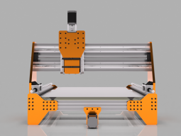
Vertek CNC - 1000mm x 750mm Linear Rail on C Beam
Build in 'CNC ROUTER BUILDS' published by EvanBruner, Aug 12, 2016.
C beam gantry with steel guide rails!
-
-
Build Author EvanBruner, Find all builds by EvanBruner
-
- Loading...
-
Build Details
- Build License:
-
- CC - Attribution NonCommercial - CC BY NC
![[IMG]](proxy.php?image=http%3A%2F%2Fi.imgur.com%2FPQIq3O9.jpg&hash=7da53afbcf471d0643689e4864d16c92)
![[IMG]](proxy.php?image=http%3A%2F%2Fi.imgur.com%2F5JDVKOR.png&hash=0bb11bbea474c735f39fbbec99c1deb1)
![[IMG]](proxy.php?image=http%3A%2F%2Fi.imgur.com%2FbaTj3iD.png&hash=897baabc303bc65d8d4d0633dd454e7c)
![[IMG]](proxy.php?image=http%3A%2F%2Fi.imgur.com%2FnWl8AQI.png&hash=b2c60aec0451b54fd91ee4afdfc48dcb)
![[IMG]](proxy.php?image=http%3A%2F%2Fi.imgur.com%2FCLYTLky.png&hash=a518701e9e045bc79bc3c38e47b23e2c)
![[IMG]](proxy.php?image=http%3A%2F%2Fi.imgur.com%2FLMMMYRD.png&hash=fc067d11bae3423af64b77927f4fd602)
![[IMG]](proxy.php?image=http%3A%2F%2Fi.imgur.com%2F71rzGNz.png&hash=0b5cf1383398b2f9c41a23a18415cf3f)
![[IMG]](proxy.php?image=http%3A%2F%2Fi.imgur.com%2FPJDw4GR.jpg&hash=3cb1882bfdb58ff747b416961eabd042)
![[IMG]](proxy.php?image=http%3A%2F%2Fi.imgur.com%2F9Vj5Lwt.jpg&hash=bfb695da9f8724198643f0798be7c3a8)
![[IMG]](proxy.php?image=http%3A%2F%2Fi.imgur.com%2FqosYzYE.jpg&hash=c8fe57ce711ca8e063b66d5304fd22bd)
![[IMG]](proxy.php?image=http%3A%2F%2Fi.imgur.com%2FZkCnNMm.jpg&hash=56b397def94d5a8e2c5e04b44a450767)
![[IMG]](proxy.php?image=http%3A%2F%2Fi.imgur.com%2FtAcAtQB.jpg&hash=561336ca07648b452fc65eadb399d3b2)


