
Hey Guys:
So, I've been building quite a few Workbee machines for clients, and I've come up with a few improvements that are easy and cheap to do, which should help the overall rigidity of the machine and address some shortcomings in the design. (my opinion)
First and foremost, I addressed some marginal design with the base of the machine. The original design for the 1000x1000 has only 2 supports under the spoil board, spaced quite widely apart. I think this is insufficient support for the bed, so I set out to modify it a bit without going overboard. The outside edges of the spoil board have absolutely no support at all, which to me, is unacceptable.
UPDATE: RECENT KITS FOR THE 1000X1000 NOW COME WITH 3 20X80 RAILS FOR THE BASE)
First thing I did was added another 20x80 mm v-slot to the mix, and moved the two existing ones to the outside edges of the base, 20mm from the side C-Beams. This just involves sliding them over. I line up the outside edges of the v-slot with the corner of the black cast angle bracket on both ends, since it is exactly 20mm wide. Makes alignment easy. I removed the two 20x40 supports from the underside of these two v-slots as well. More on that in a moment.
I then added another 20x80 in the center of the base, attached in the same manner as the other two, again without the 20x40 "foot". The bed now should have plenty of support. I put 4 tee nuts in the top side outer slots of each of the two outside rails, and also in the top slot on the front and rear rails. These tee nuts will be used to fasten down the spoil board later. I usually drill the spoil board and put screws down through it into the tee nuts . It's a bit difficult to get these to line up sometimes, but worth it in my opinion. (might be easier to use post assembly drop in tee nuts instead, but they are just as fussy to install) The screws going through the spoil board on the front and rear rails are recessed (using a 1/2" forstner bit) so they don't interfere with work that may be longer than the bed. The ones on the sides are out of the way and don't need recesses. Note that I usually flip the tee nuts upside down with the extruded thread collar facing up. This give just a bit more height to engage the screw threads when mounting the spoil board. UPDATE: RECENTLY, I HAVE STARTED USING "TEE-BOLTS" ON THE SIDE RAILS, WHICH ARE 5MM BOLTS WITH POST INSERTION HEADS. THESE ARE MUCH EASIER TO INSTALL, AND JUST USE A FLANGED NUT ON THE TOP. THEY ARE AVAILABLE ON AMAZON. I ALSO NO LONGER PUT SCREWS ON THE FRONT AND BACK RAILS, FROM THE TOP OF THE SPOIL BOARD, I JUST USE 2 HOLE BRACKETS FROM THE BOTTOM.
Now that the bed is a bit better supported, I turned my attention to the 20x40 "feet" used to support the 20x80's. In the original design, they are mounted parallel to the 20x80's underneath to support them. This, however, does nothing to increase the strength of the bed or tie anything together. So, I cut them down to 875mm in length, and mount them transverse to the 20x80's across the width of the machine. It's important to cut them off so they don't interfere with the inside plates on the Y gantry. They should end up flush with the outside edges of the 20x80's.
This ties all the bed supports together, and still provides a support for the 20x80's to keep the bed level. I used 3 x 4 hole angle brackets to tie the 20x40 cross braces to the 20x80 longitudinal supports, forming a cross braced system which is much stronger than the original. I mount these two evenly spaced between the end supports, about 333mm from the front and rear rails and each other.
This is what the final mod looks like.
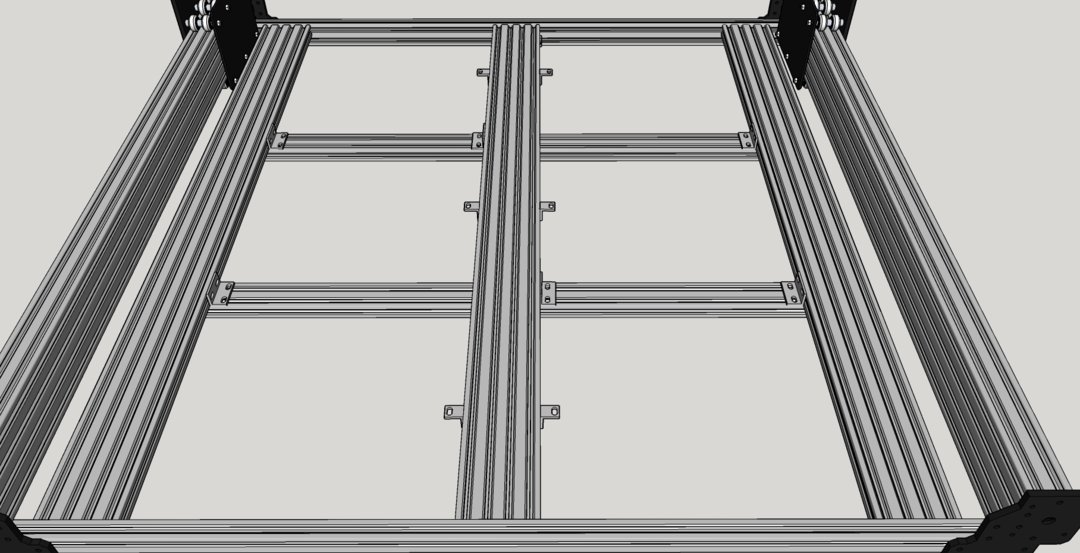
Note the 6 x 2 hole angle brackets on each side of the central 20x80. It's much easier to just mount these on the 20x80 and put a wood screw up through the bracket into the spoil board after it's mounted, than to drill through the spoil board and mount it with tee nuts and screws like on the perimeter. Use a #10 x 5/8" wood screw to avoid punching through the top.
One other minor modification to the base, I noticed that the black 2 hole joiner plates that are "end caps" for the front and back rails only serve a cosmetic purpose. Since I like things to follow function as well as form, I substituted 3 hole joiner plates for the two hole, and tied the third hole into the bottom rail of the C-bean via a screw and tee nut. Now at least the plates add a bit of strength to the c-beam mounts. It is arguably a small improvement, but I'm all about small improvements. They add up to become large improvements. Note that I use self tapping screws in the ends of the 20x40's to avoid having to tap the holes.
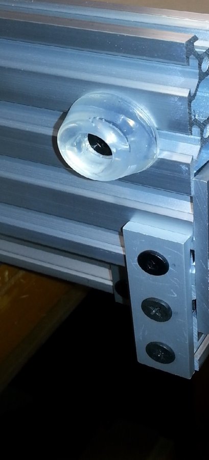
This photo is actually from an Ox HD, but it's the same principle.
The next thing I didn't like about the Workbee is the X and Z axis plates and how they attach. Firstly, a rant about plate design. The Z axis plate and the front X axis plate on the Workbee are different. There is absolutely no reason for this. With a bit of careful design, both plates could be identical, therefore reducing manufacturing time and having less individual parts to deal with. As a matter of fact, they could have just used the C-Beam XL plates from the OB store and avoided having to do a new design altogether, except for the fact that there are 4 sets of wheels instead of 3. Just a couple of extra holes in the CBXL plate design and they could have used the same plate for both. I guess this is a personal gripe for me, but I'm all about efficiency of design.
Same thing goes for the base end caps for the c-beam used on the Workbee. Instead of making 2 separate part numbers, a left and a right, they could have made them all the same by simply drilling the bearing hole all the way through, and using a flanged bearing. Eliminate the screw reliefs, which are just cosmetic anyway, and the part is now one sided and does not require machining on both sides, eliminating another manufacturing step. Again, less parts = lower manufacturing cost. This also applies to the Y gantry main side plates. Drill the lead screw bearing hole right through and use a flanged bearing. There are also 2 pockets for screw heads for mounting the idlers for belt drive, not really necessary. Nobody uses belt drive anymore... Eliminate the three items and the left and right plates become identical, thus eliminating another part number. Also, this part now becomes a one sided part as far as machining goes, saving time and labor.
Ok, Ok, these are personal rants and just the way I would have done things. However, I have a really big pet peeve with the Z axis mounting arrangement on the Workbee. The designers used (8), count em, 8 bolts with nylon lock nuts to mount the Z axis. A bit overkill, IMHO. But, the biggest problem with this is that these bolts become completely inaccessible once the X/Z are assembled together, making it impossible to do any service on the Z axis. You have to completely disassemble the X/Z axis to do any repairs or adjust the anti backlash nut on the Z. This is crazy. Fortunately, I came up with an easy solution. Just use the 4 screw holes on the outside left and right of the Z axis to mount it, do not use the inner hidden holes. I tap out the holes on the X axis plate with a 6mm tap, which , fortunately, requires a 5mm hole, so no need to drill out the hole. Then I drill out the 4 mating holes on the Z axis plate to 6mm for clearance on a 6mm screw. Now, the entire Z axis as an assembly simply bolts on with 4 accessible screws, and is easily removed for service. Makes much more sense to me.
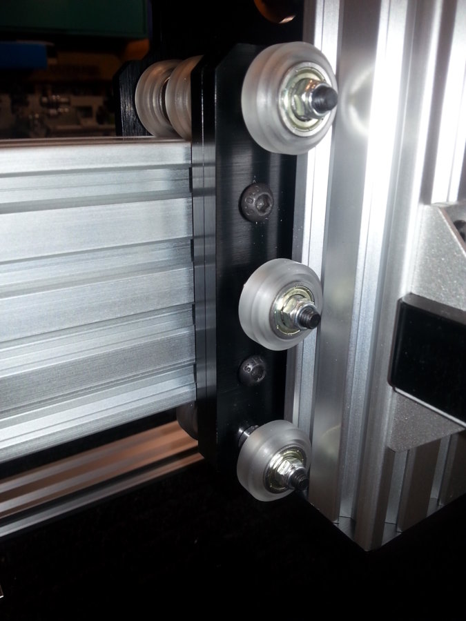
You can see two of the 6mm x 12mm screws between the wheels in the photo. Plenty strong, and much simpler.
That's about it for now. As I build more of these, I'll probably come up with some more suggestions for improvement. Ooznest, I hope you are listening.
Metalguru
PS - Most of the mods here were done with the existing kit in mind. You would normally need to add only a few parts to the kit to do the mods I have described. I think if I was building one of these from scratch instead of using the kit, I would likely just use 3 x - 40x40 v-slots for the spoil board support, running front to back and attached with 4 hole corner brackets on each end. Or a 40x40 on each side and a couple of 20x40's on edge in the center. This would provide even better support for the spoil board, and the machine in general. I have actually built one like this, and it worked out well.
I would probably also use C-Beam XL plates for the two X and Z axis plates, but with only12 wheels instead of 14. I wouldn't think this would make a huge difference in strength, it's less than 12% difference in the number of wheels. This is assuming screw drive and not belt drive.
By the way, Chris Laidlaw now offers Workbee side plates in a 1" taller version for a bit more Z axis clearance. You can see them on Ebay at Chrisclub1.
MG")
Some Improvements on the Workbee 1000x1000
Build in 'CNC ROUTER BUILDS' published by Metalguru, May 12, 2021.
Improvements both real and suggested for the Workbee assembly
-
-
Build Author Metalguru, Find all builds by Metalguru
-
- Loading...
-
Build Details
- Build License:
-
- CC - Attribution - CC BY