
We all know that 3D printers are great and you can fab all kinds of new brackets and holders but the reality is, every fab shop needs a CNC router.
This is because when it comes to making flat plates (and you will need them) or 2.5d designs for builds the router can't be beat in time and/or materials used.
You can mill all kinds of really strong parts from Plexi to Garolite (phenolic board) even aluminum. In most cases less time then a 3D printer can get the first few layers down.
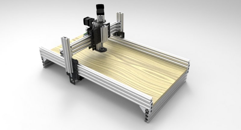
Routy is a great little starter CNC router. It will teach you how everything works and once you complete the build you will know much more about CNC machines in general for very little cost. A neat feature this machine has is the ability to raise/lower the X/Z axis assembly to allow for thicker materials such as 2" foam board. You don't have to build it this way but by leaving the Y axis towers longer (like shown) it allows you this added feature.
One really cool aspect of this little machine build is that all its parts are standard OpenBuilds Part Store parts so it can be built without any custom plates.
Once this machine it built it can be used to make custom parts for all kinds of other machines even stronger routers
*NOTE: This layout is not so much a step by step build, as it is more of a reference of photos to study while using the 3D model for the main understanding of the build.
Please know that the gallery pictures take a while to load, please be patient.
______________________________________________________________________
STEP 1 - Build the Y axis gantry plates


______________________________________________________
STEP 2 - Building the main frame and attaching Y axis gantry plates


______________________________________________________
STEP 3 - Building X axis gantry


______________________________________________________
STEP 4 - Attaching Z axis to X axis


______________________________________________________
STEP 5 - Attaching Z/X assembly to Y axis


______________________________________________________
STEP 6 - Removing Z axis plate to attach V-Slot for router mount
You do not have to mount V-Slot to the Z plate here. You could instead mount a set of brackets for the dremel to attach to.


______________________________________________________
STEP 7 - Attaching electronics holder cross brace and box


______________________________________________________
STEP 8 - Software
We used GRBL Sheild with GRBL Controler for the Hardware/Software


______________________________________________________
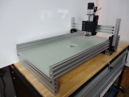
Reference Build Photos


_______________________________________________________
PARTS LIST:
Under Files Tab
__________________________________________________________________
The model dimensions as well as a few other minor changes are not shown in the pictures. So be sure to go by the model for your build.
Download model in Files tab at the top of this post
ROUTY CNC Router (V-Slot Belt & Pinion)
Build in 'Cartesian Style CNC' published by Mark Carew, Jun 5, 2015.
A cool little CNC router build that uses the V-Slot belt & pinion drive and stock parts.
-
-
Build Author Mark Carew, Find all builds by Mark Carew
-
- Loading...
-
Build Details
- Build License:
-
- CC - Attribution - CC BY
Reason for this Build
We needed a shop router that can do light duty milling .Inspired by
Belt n Pinion System - Shapeoko -
Attached Files: