
**This build needed to be re-submitted due to a web editor problem on the site.**
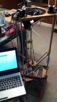
As the front page build photo shows this is still very much a work in progress. I've only recently gotten everything hooked up and am still in the configuration stages. So far I have Marlin and Repetier working and have done a basic extrusion test with my home made hot end ($12 worth of hardware store parts, a self made heater block, 40W/12V cartridge heater, and a standard 100K EPCOS thermister). I'll replace this awful photo when I've cleaned up the wiring, made a top cover, printed an LCD display cover, etc.
The only parts that were 3d printed on this were the Aitripper V3 Bowden extruder parts, all other pieces usually 3D printed were fabricated from MDF and then polyurethaned. This is not an original build - I am copying the technique used by Jonathan Keep (http://www.keep-art.co.uk/Self_build.html) who made a ceramic extrusion delta bot. I definitely recommend checking out his artwork. I chose to make this build as an FDM type using 1.75 mm PLA filament and a 0.5 mm nozzle opening.
I'll post more photos of the build soon. If anyone is interested I also made CAD drawings for the MDF components that are posted in the Files section along with a BOM that includes prices and source.
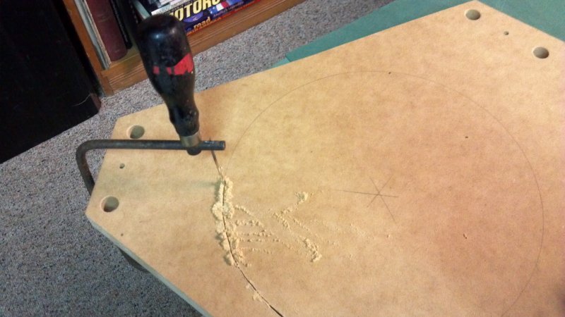
The power tools used in fabricating the MDF components were a tablesaw, a belt sander, a drill press, a hand held power drill, and a Dremel too. I could have used a router for cutting the radial opening in the top plate but didn't really want to go out to my unheated workshop in January so I used a hand coping saw. That said, there is no reason why all of these operations could not have been done with hand tools alone or with only a hand held power drill. A drill press really helps to maintain proper alignment tolerance when boring the holes for the bearing rods, however.
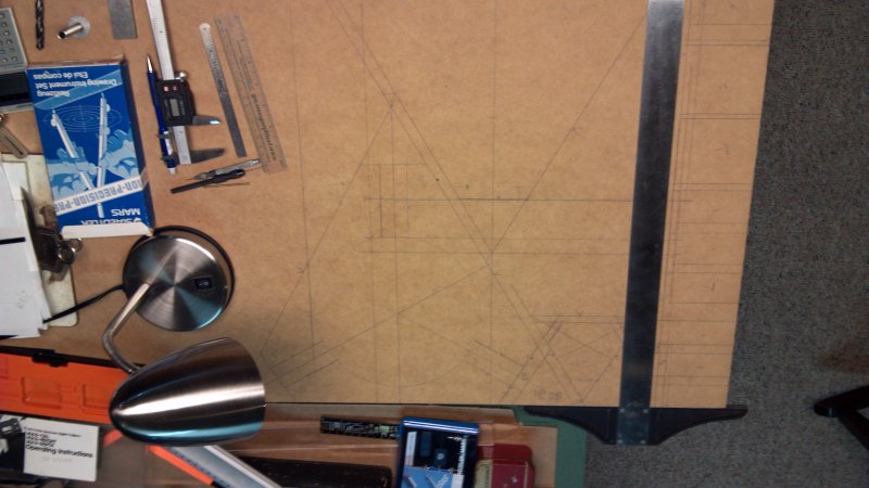
Here's a general outline of the process. First I laid out the outline of the components on the MDF. A set of digital calipers and a T square is helpful.
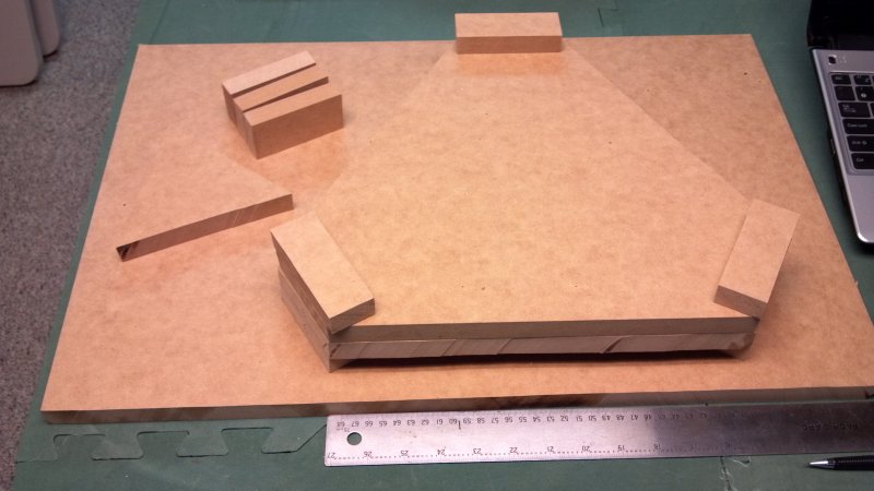
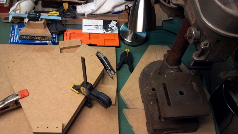
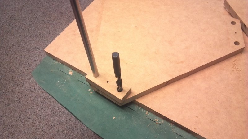
Line up the top plate, the bottom plate, and the bottom rod support blocks, clamp them together and then drill pilot holes (I used a 5 mm drill) for the bearing rods and the screw hole for the support block. Use the mid point screw hole to hold the three pieces at each corner while boring the 12 mm holes.
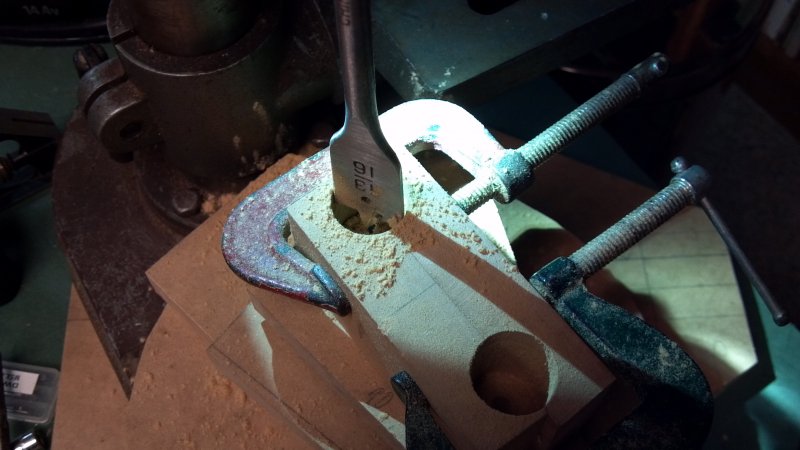
Clamp two carriage blocks together (you'll need an extra one), drill a pilot hole and then use a 13/16 spade end bit to bore the bearing cradles in the blocks. Use an inexpensive spade bit as the higher end ones cut too aggressively and throw the blocks. The drawing files show the cradle as offset - I later decided to use this method as it was easier to create the offset with a piece of clear tubing at the bottom pulley plate.
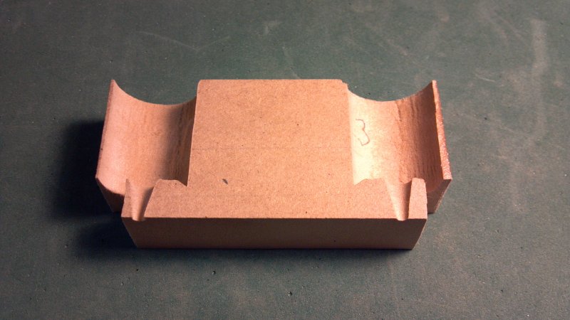
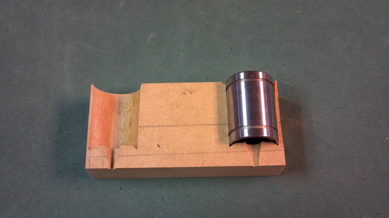
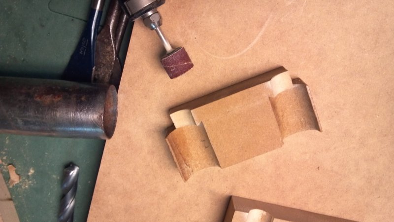
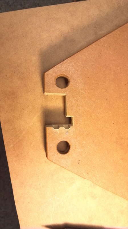
Make the corner cutouts and grind a clearance recess for the bearing rod. Drill holes in the sides of the cutout area for the effector rod attachment screw (uniform placement) and holes for the zip ties (see below).
Cut the center opening in the top plate. The drawings show the top pieces as an assembly because that is the way Jonathan keep originally designed it. Separate pieces allow some adjustment of the rods to ensure they are parallel and makes it easier to disassemble for transport. Because I was able drill the holes and maintain the tolerance all right, I decide to keep it as one piece. File the opening with a rasp or sand it to smooth the cut (or just use a router in the first place).
After you cut the notches described below, wipe everything down and give it two coats of polyurethane. I rubbed it on with a lint free cloth and let it dry between coats. If the side walls of the bearing cradles seem cracked or too fragile, soak in a bit of cyanoacrylate ester glue (Superglue) before coating them with polyurethane.
At this point you might be wondering why did I bother doing all this when I could have bought 3D printed components and had it all assembled by now. Well, I have the tools, had time this winter, and I find planning and building this way relaxing. The next one will use printed components.
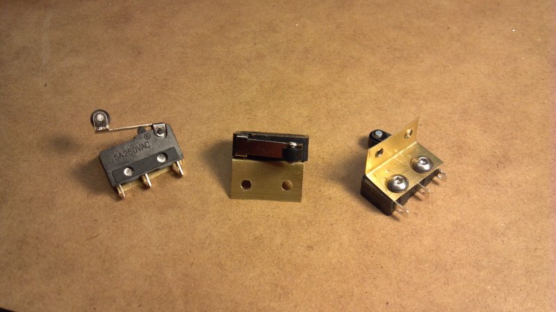
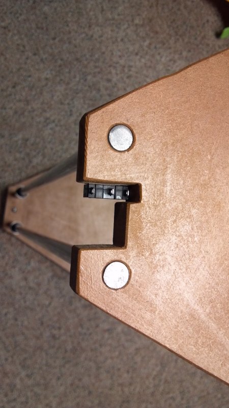
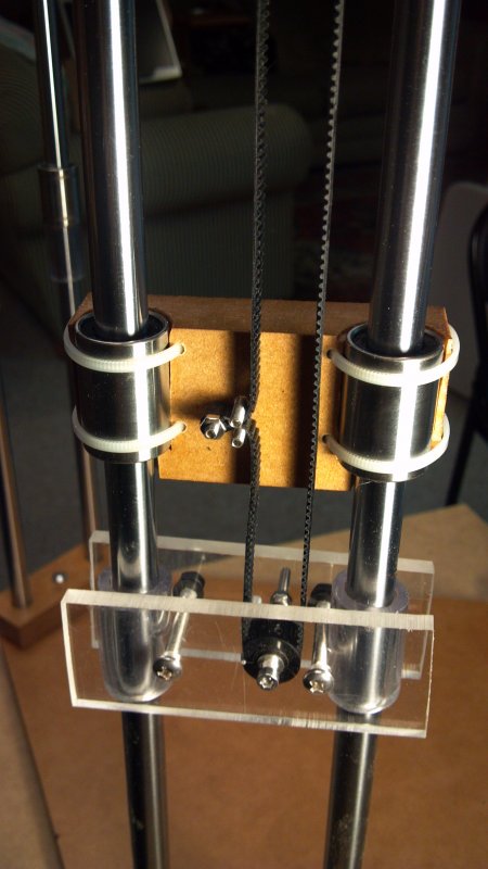
Brass shim stock was used to create a basic right angle bracket for the mechanical endstop switches. A slots for belt clearance and a notch with screw head clearance were made in each corner of the top plate. The end stops were screwed in place with the wire terminals upward (you can solder the endstop wires on first or do it later - see below for the connection order). Place the bearings and clear tubing for the pulley plate offset below them onto the rods and then place them into the 12 mm holes in the plates and tap the plates in place using a rubber mallet or a hammer a a wood buffer block (switch terminals up!). Check the rod spacing at the top and bottom with digital calipers. Now is the time to correct it if you can't hold a carriage on the bearings and slide it up and down without any binding. Re-drill if needed by building up the hole diameter with wood glue mixed with MDF dust or cut the top plate into separate pieces as Jonathan Keep did.
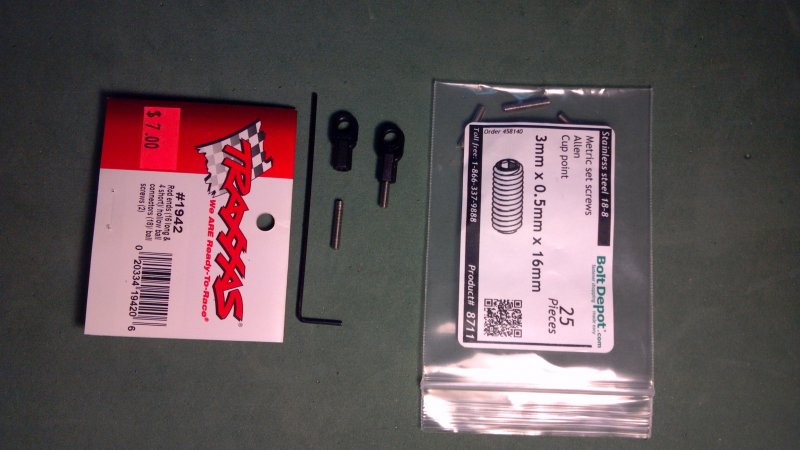
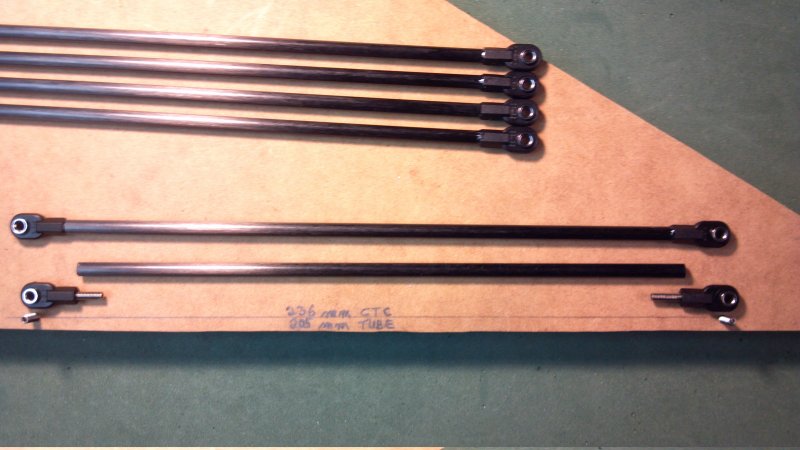
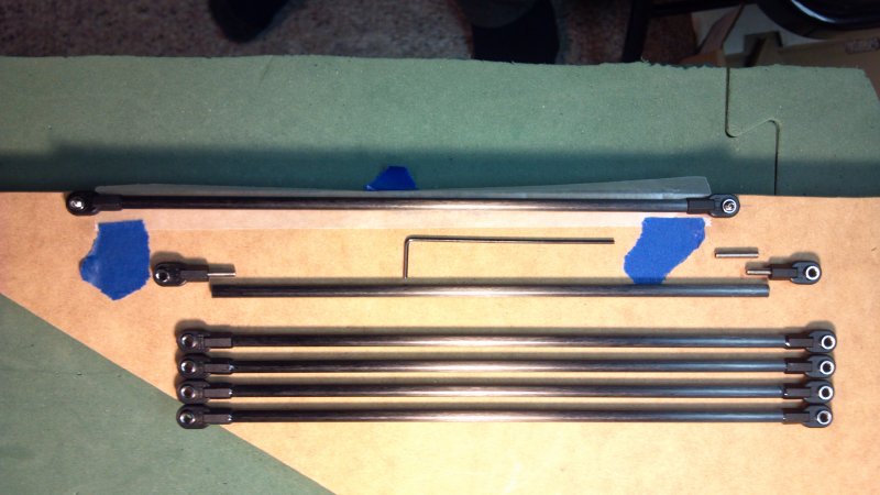
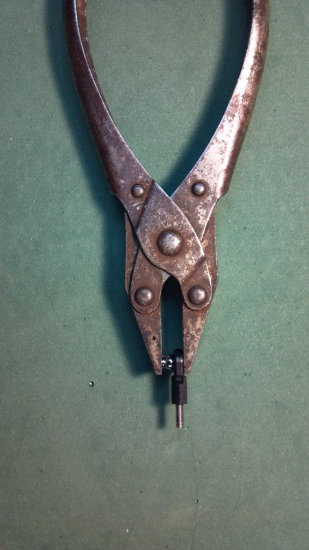
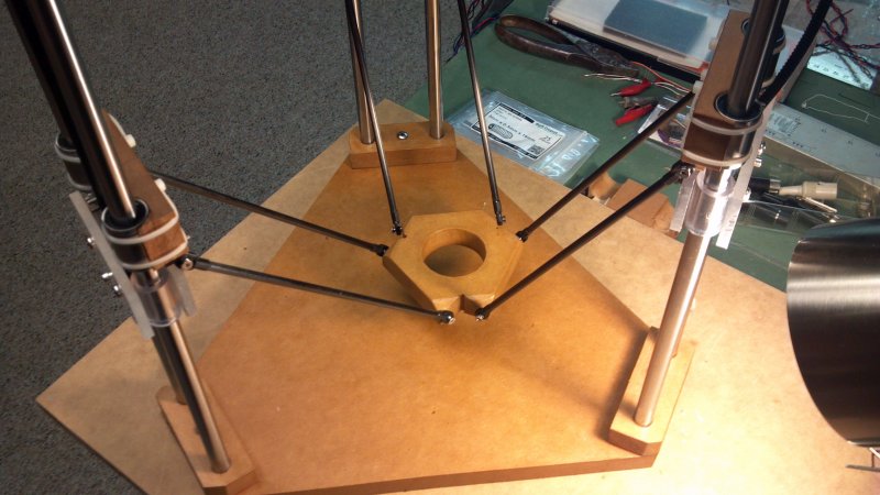
Make a jig for gluing the carbon fiber rod assemblies in place by threading two 3 mm set screws into holes in a board. I used a spacing of 236 mm. The tube length is then 205 mm. Thread 3mm set screws into the Traxxas rod ends after snapping the ball ends into the socket ( I used a set of parallel jaw pliers for this but pressing firmly on a hard surface should do.) Check the fit of the set screw in the carbon fiber rod - the hole may need to be opened slightly with a drill bit if won't slide in. Put epoxy glue on the threads of the set screws and slide one in each end of the rod, wipe off any excess glue, and place the assembly on the jig screws and let it dry (be careful that trapped air doesn't push the Traxxas rod end outward). I used waxed paper under the assembly to keep it from sticking to the board.
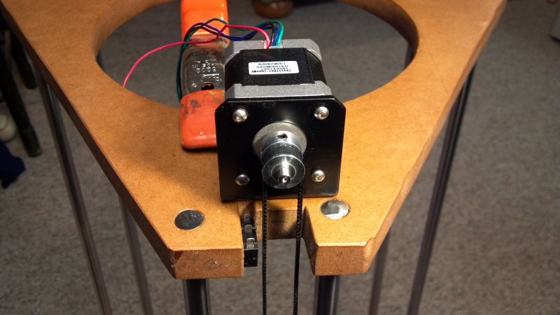
Clamp a motor in place so you can determine the sideways offset of the bottom pulley assembly. The bottom pulley is mounted on a brass tube which slides over the mounting bolt between two 5mm or .25" acrylic plates. Drill mounting holes in the bearing carriages for zip ties along with three holes for 3mm set screws used to retain the drive belt. A nut is used on one as a retainer. After you get everything lined up, mark the bolt holes for the motor in the top plate using the screw holes in the mounting bracket. Once the bearing carriages are in place, use conical headed 3 mm screws to attach the effector rods to the bearing carriages and effector. Don't forget to first drill the holes in the effector for the hot end mounting screws like I did.
It took me a great deal of time to figure out the correct controller configuration to be able to get the system running well enough to test as I'm not a programmer and fairly new even to the use of an Arduino. The Marlin file I'll add to files section should be taken as a starting point – it will need to be tweaked and will change as I make changes to the system (i.e. “in progress”). Check the links that will be kept at the end of this build description for a better explanation of the controller setup than I can provide.
In order to test the Ramps 1.4 controller it's necessary to have the thermisters wired in (or at least a resistor) in addition to the motors and endstops. I wired the endstops as normally closed (NC) and the Marlin file I'll post reflects that. The drive motors are capable of 0.9 degree stepping and the extruder is 1.8 degree but is capable of higher torque. The extruder probably would function better with a geared stepper. I decided to get the heat bed and hot end functional before working on the delta positioning aspects.
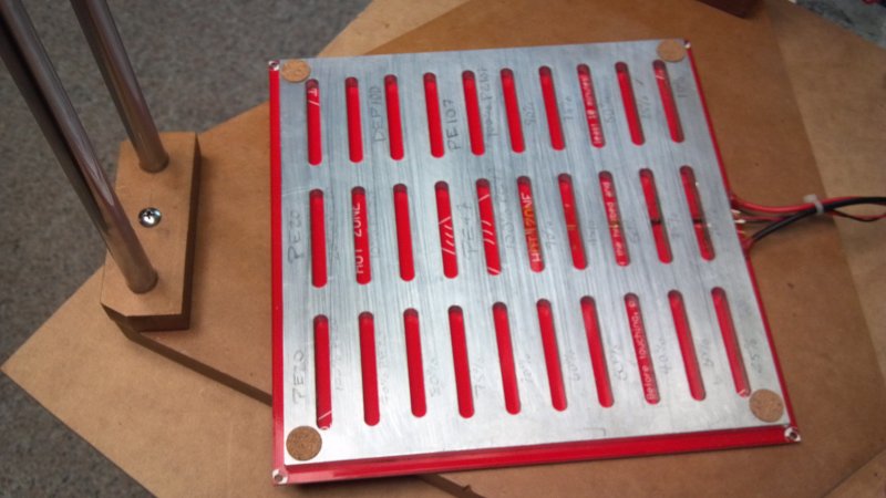
I stumbled on a milled aluminum plate in a scrap pile that was perfect as a base for the standard heat bed and so I bonded the bed to it with high temperature silicone adhesive after drilling a center hole for the thermister and grinding a channel for the wire. I'll eventually add leveling screws but for now it has cork pads at the corners.
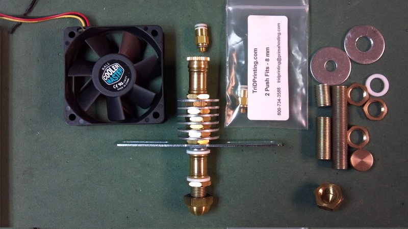
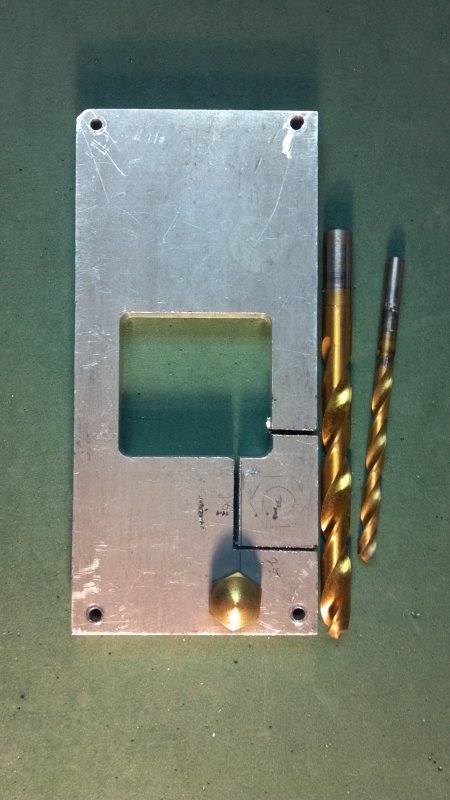
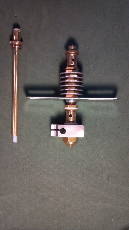
The hot end was fabricated mainly from lamp parts and aluminum and teflon washers (the threaded shafts shown are hollow). The cap nut was mounted on one of the threaded shafts in a drill press to file it to a cone with ~2mm diameter flat tip and to drill a nozzle hole (see youtube link below). The top cap was drilled and tapped for a push connector for a Bowden extruder tube, and vent holes were drilled in the 2 brass couplers. Cost for the parts used not including the push connector and fan is about $12.
A brass tube was cut to length and one end tapped to thread onto the inside end of the push connector threads, the brass tube was lined with a slightly longer teflon tube (same as the Bowden tube) that ends just above the inside of the nozzle and another short section of teflon tube with the same OD as the brass tube was put over the protruding end of the smaller diameter teflon tube as reinforcement. This lager dimeter section is pressed down on the interior nozzle surface when the tube/cap/push connector assembly is screwed onto the upper end of the threaded hollow shafts. The brass connectors used to connect the threaded lamp shafts were drilled to allow ventilation around the interior brass/teflon tubes. The aluminum washers had to be drilled to a slightly larger center hole. A heater block was cut from scrap aluminum and drilled for the nozzle shaft and heater cartridge along with splitting the side and tapping a tab to allow clamping the cartridge. This hot end is definitely still experimental but initial tests at least show it's functioning.
(Credit: Alan Long (Youtube))
See the Files and Drawing tab for Bill of Materials list and drawing files as PDF or DWG.
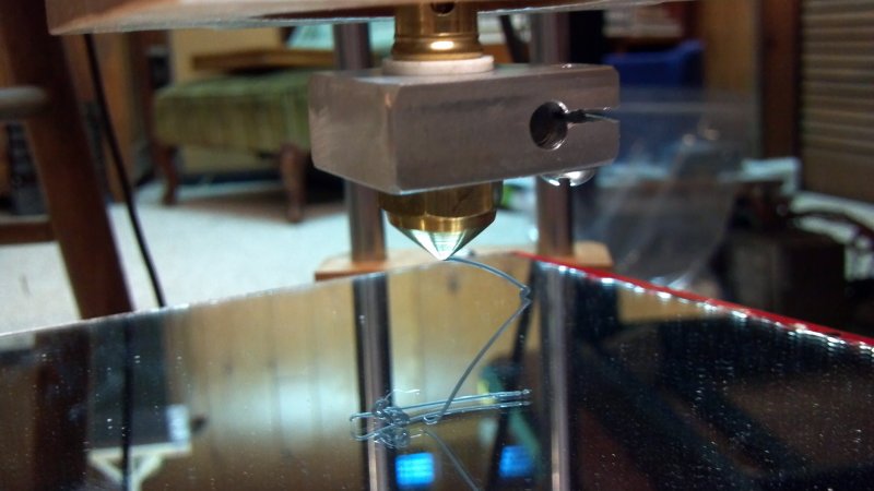
First test print using home made hot end (see AVI file):
(First layer is uneven and too thin, also need to work on extruder temperature and feed rate)
MDF Delta
Build in 'Delta Bots' published by nicklogan, Apr 28, 2016.
A Rostock style delta bot with the parts which are typically 3D printed made from medium density fiberboard (MDF). It uses a home made hot end.
-
-
Build Author nicklogan, Find all builds by nicklogan
-
- Loading...
-
Build Details
- Build License:
-
- CC - Attribution - CC BY
Inspired by
See Special Notes. -
Attached Files:
