
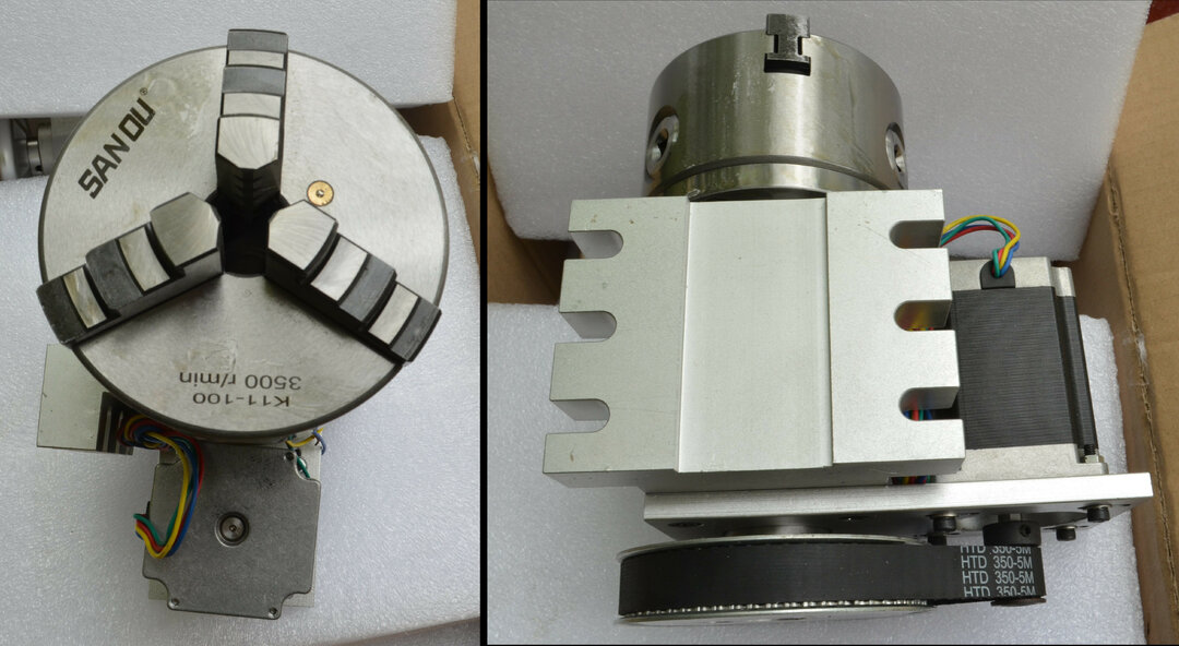
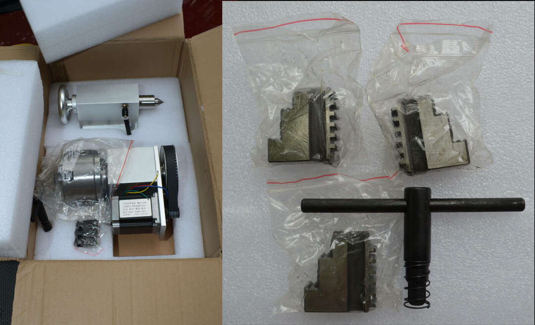
I have been toying with the idea of making a 3 axis rotary CNC machine for awhile. I wanted to make it with off the shelf OpenBuilds parts so anyone can replicate it. All parts are available from OpenBuilds except the rotary axis. The rotary axis is available from various online retailers and ebay. I purchased a 100mm 3 jaw chuck and tail stock from here: https://www.ebay.com/ipp/113664230428?transactionId=2078159169001
I looked into the Openbuilds CNC Lathe section in the "Builds" portion of the forum and only saw one marked as complete. My goal is to double that. I mulled over various designs in my head, but the easiest starting point I could think of was the LEAD High Z mod so I purchased the kit. I had a 1500mm 2080 V-slot piece and a 2040 V-slot left over from another project so I purchased the High Z mod kit, another 1000mm 2080 V-slot piece, and additional C-beam and the other parts for the gantry to match what came in the High Z mod kit. I had some left over 2040 V-slot from another project for the cross brace. I am starting to assemble parts, but I am also not 100 percent set on the design I have posted here in the files section. Maybe someone else has good ideas that will help. Originally, I was going to cut some custom braces from aluminum plate, but decided to order some Adjustable V-Slot Hinge to use with the 2020 extrusion I have left over from an earlier laser project to keep it all “off the shelf.” The stacked pieces of 2080 was just an idea, but I am not married to it. I may make something out of another material.
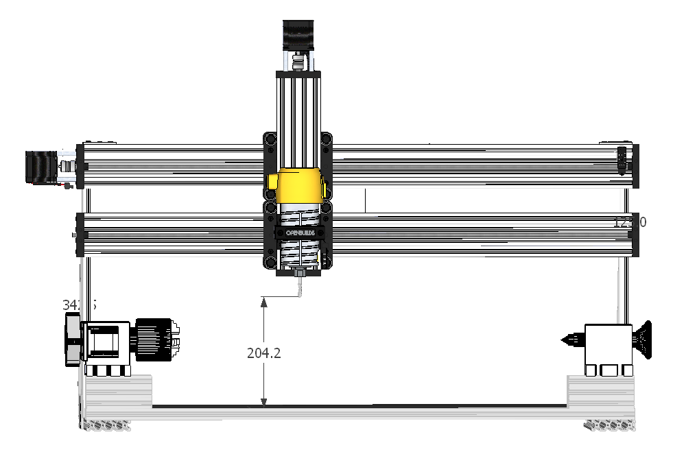
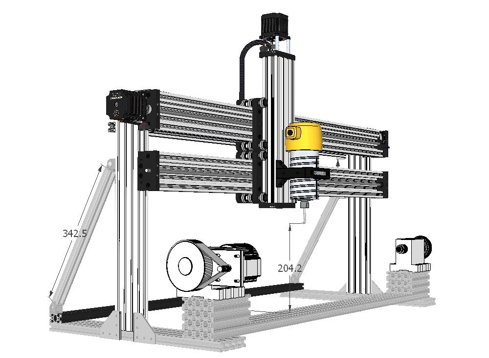
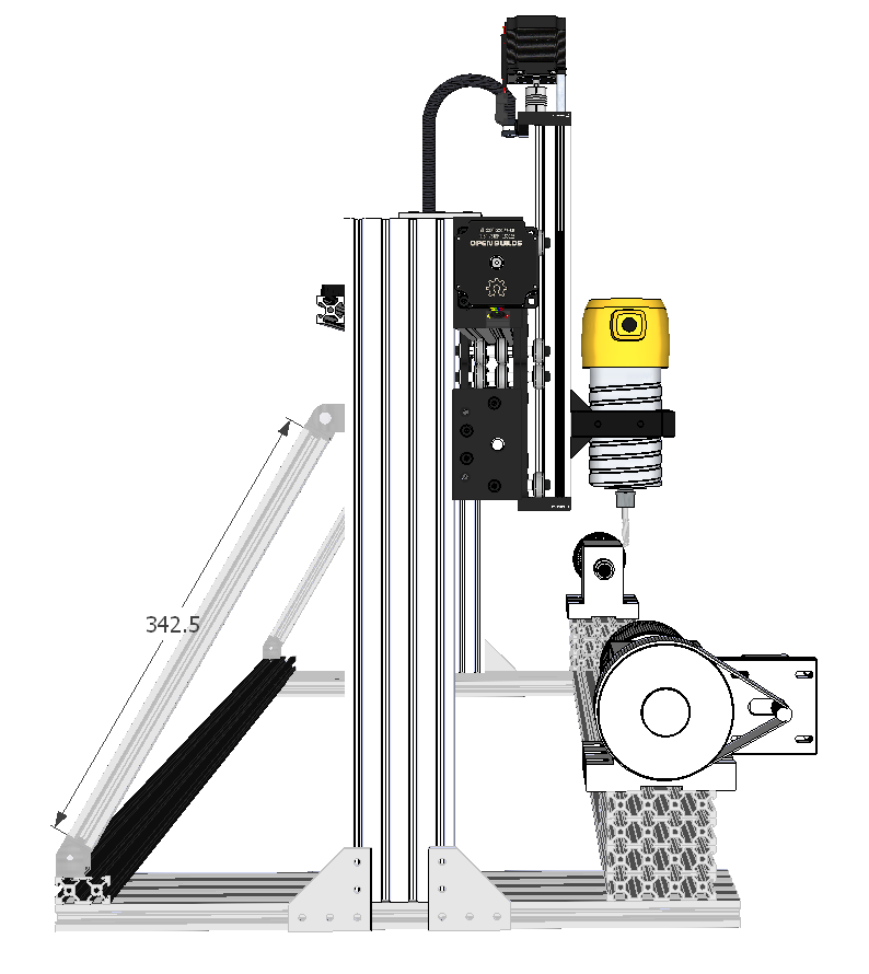
Here are a couple of pictures from my design as it is now. This may be one of those designs where I go off the drawing I have, but make design changes on the fly and modify the design drawing after if I like the change.
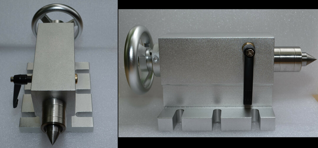
I am actually very impressed with the rotary axis I purchased. It was very well packed and looks very nicely made. That being said, I have yet to hook it up and use it. Here are a few pictures of it:
August 8:
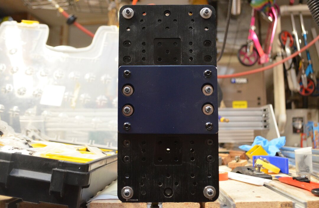
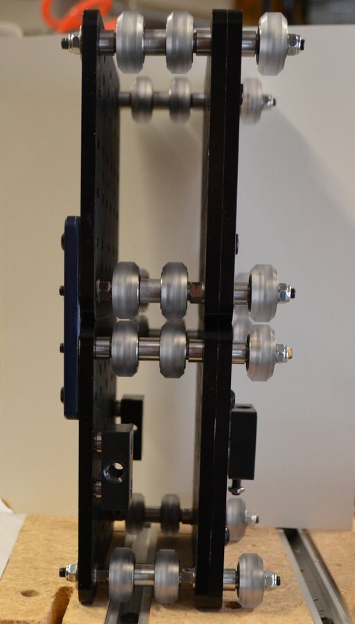
I finally got more time to work on this in the evenings this week. The first thing I did was assemble two sets of extra wide Cbeam Gantry plates as per the OpenBuilds LEAD video instructions and using the OpenBuilds components listed in the video. Upon doing this I realized that since I want 8 wheels guiding my Z axis up and down for extra rigidity (I hope) I would need a plate to tie these two plates together. I came up with a solution that turned out to be overly complicated, so a solution to my solution was found. Basically I used my CNC router to mill an 8 holed plate that would incorporate the 4 axle screws and existing threaded holes on the gantry plates. This goes against my goal of no custom plates, but this could easily be cut and drilled by hand out of aluminum or plywood, or 3D printed. The other option is to mount it just like the High Z mod for the LEAD where the Cbeam holds the plates together with a moving Gantry cart carrying the spindle. I may choose to ultimately go that route but for now I will try this method first. If someone else chooses to do this build, I can make the plates I came up with for them or just provide the file and they can cut it themselves.
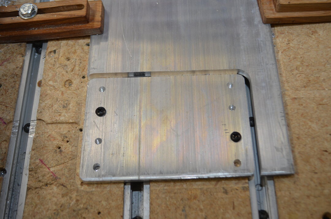
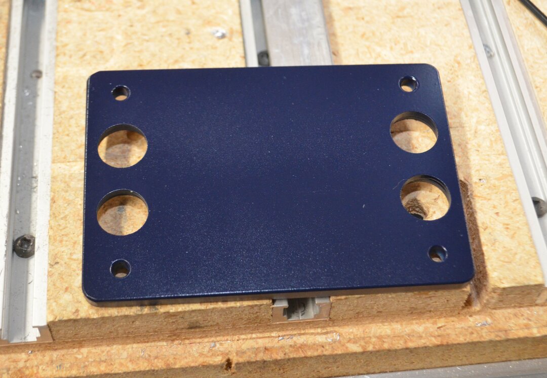
Then I realized I would need longer axle screws and would have to disassemble everything. Therefore, I just drilled out the two holes where the axles could poke through with a step bit. I gave it a nice coat of Navy Blue to see if I like the color. I do, but I think sticking with all black would look better.
Prior to tightening up the screws (Four 12mm m5 screws) holding this on the gantry plates, I put both gantry carts on the Cbeams for the X axis and inserted the 500mm z axis Cbeam and tightened all the eccentrics on the wheels. Then I squared it all up and tightened the joiner plate.
August 9:
A little further progress. I realized I forgot to order the 90 Degree Joining Plate so I made my own slightly narrower plates because I had a narrower scrap piece of 6.5 mm aluminum. I like the way they look, and it got rid of aluminum that I otherwise had no use for at the moment. But the 90 degree joining plates would absolutely work for this, after all they are used in the LEAD build.

I then mounted the uprights to the two C-Beam® Linear Rails, put on the C-Beam® End Mount using four 25mm Low Profile Screws per end mount. I also installed the 8mm Metric Acme Lead Screw, shaft collars, 8mm washer, and 8mm bearing as per the LEAD instructional video. Ignore the Covid-19 hoarding of Crunchberries and Froot Loops by my 14 year old in the background of the picture. Priorities! Also, the lathe build is resting on the rear of my existing CNC which is why there are other plates and extrusions on the bottom of the photo.

However, my C-Beams are mounted on the front of the uprights rather than the rear in the other builds. This lead to some concerns with the lock collar set screw. When originally put on and tightened down (not all the way) it would hit the upright 500 mm 2080 V slot as the lead screw rotated.

After debating how I would solve it, I just tightened them down as hard as I safely could with an electric screwdriver and the problem solved itself. I also added additional corner brackets using 8mm low profile screws and Drop In Tee Nuts where I couldn't use the Tee Nuts - M5 (10 Pack).
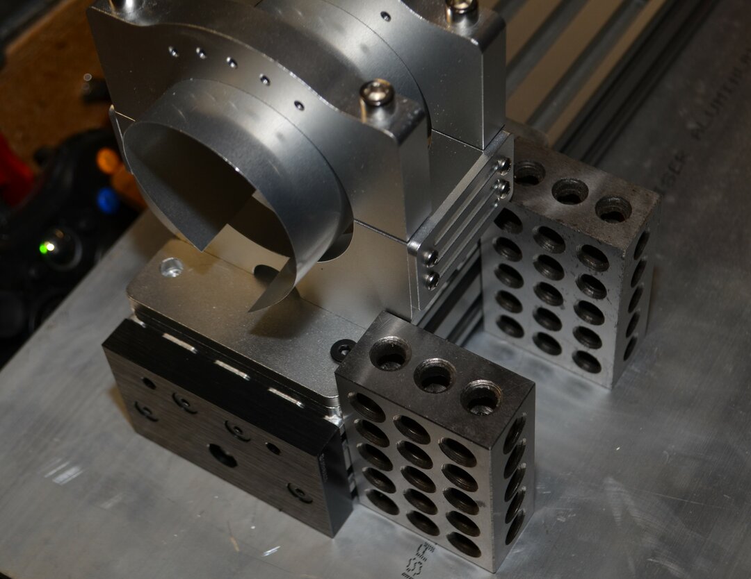
I had purchased this spindle mount from ebay (I wish OB sold a 65 mm mount

Unfortunately for me, I did not see the four large M6 socket cap screws protruding 6 mm out the back, or it would have been an easy mount to the z axis C-beam. Back to Fusion 360 for a custom plate from 6.5mm aluminum.

I milled it real quick, but had an oopsie! Remember to make sure that end mill is tightened down real well in the collet.

Ah well. It is fully functional, but upside down in the picture which is why the holes do not line up on the bottom.

Now it is time to start assembling the Blackbox (Ghost Version).
August 23:
Black box Ghost Edition assembled.
Wow! Time has flown by and I have not got much done since the last post. So, as of today (September 25):
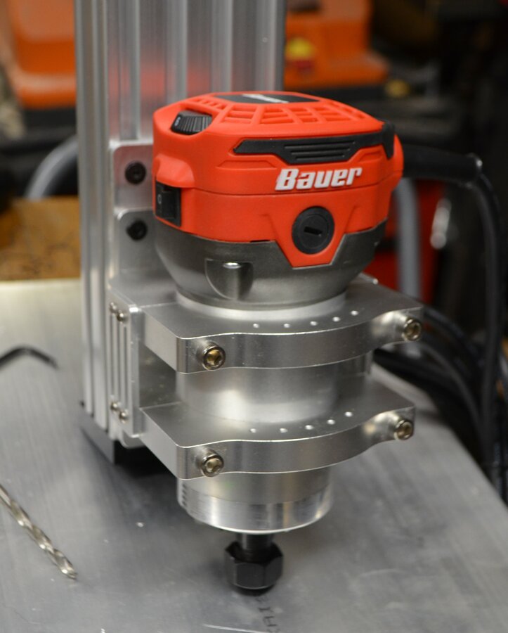
I attached the spindle mount to the plate and made sure the plate was square to the c-beam using some 1-2-3 blocks. You can also see the sheet metal shim I needed since my Fake-ita (Harbor Freight Version) was just a hair too small. I choose the Bauer router because it uses all the same parts (collets, brushes, etc...) as the Makita I have on my CNC router at nearly half the price (on sale). I figure it is the same quality as the other knock-offs that other hobby CNC companies sell under their brand name, so why not give it a shot.
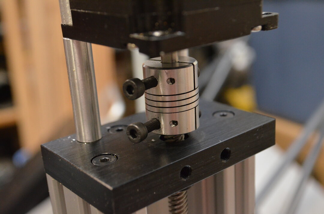
I also added the NEMA 23 high torque stepper motors. These will only be on here until I rebuild my old CNC router and then I will swap those motors over to this one. I like to add a "real" screw rather than a grub screw. They are easier to remove if the hex head starts to strip. One thing I forgot to photograph was the fact I ground "flats" on the lead screw where the screws from the coupler will touch the lead screw. I also did it where the lock collars screw hits the lead screw.
I cut two 375mm pieces of 2020 v slot from a piece 750mm long. I then attached them starting at the bottom rear with it 295mm from the back of the uprights. This put the braces at approximately 45 degrees. I used some clamps and 1-2-3 blocks to square up the sides so I could tighten up the braces and Adjustable V-Slot Hinge


First moves to test out the BlackBox and OpenBuilds Control. I am a fan! Straight forward interface. I took a bit to get it set up due to my stupidity. I could not get it to do anything and then I realized I needed to pick a set-up so I chose the LEAD 1010 just to try it out. This error did get me to triple check the wiring.
10/3/2020, I recycled an unfinished oak China cabinet base that my dad started probably 30 years ago that we saved while cleaning out a storage locker. Then I took my old kitchen door that was a solid wood (particle board) core door and cut it down to be the surface on which I will mount the lathe. I had an 8 foot length of steel tubing that made a great cutting guide for the circular saw. Thankfully all the drawer sides were packed away in a box so I can have a nice base cabinet with storage for the lathe.


10/4/2020, I drew up and cut a quick plate I could cut from scrap acrylic to connect the drag chain to the x gantry so I could easily run the z motor wire to the drag chain.


I also cut a piece of 3/16" x 1 1/2" x 1 1/2" aluminum angle I had on hand to 1000mm in length. It was mount across the back of the uprights for the drag chain to run along. I then hooked the wiring up and ran it through the drag chain. I had about 50 feet of shielded wire (4 wire) on hand so I used some of that instead of the wire I used earlier to test it.


10/11/2020 - I made a few more plates today. I wanted to beef up the braces so I designed some new angled plates. I also wanted to try engraving on them. I have never used such a small diameter endmill on aluminum before, so that was a first for me. I made 4 of them - two were engraved. There will be two on each side, but first I decided to paint all the plates black to match the OpenBuilds gantry plates.


When I ordered the High Z mod to make the Lathe, I thought it came with C-beam end plates. It wasn't until I was assembling the structure that I realized they were not included in the BOM because they are unnecessary for the functioning of the High Z Mod.
I wanted the ends of the Cbeam to look finished so I made a variant of the C-Beam end plate. These were a little longer so they would be flush with the angled plates on top of the 2080 V-Slot uprights. I put a 6 mm hole through these plates so I could run the wiring from the rotary axis through the C-Beam to the BlackBox on the other side. I made these out of scrap black acrylic I had left over from another project. I had to laminate two pieces to get the right thickness.

A quick paint job of the plates.

10/22/2020 - I am considering the 510 OpenBuilds Modular Enclosure System so prior to squaring the machine and permanently fastening it down, a temporarily mounted a piece of V-Slot® 20x20 Linear Rail down to to the table top at the rear so the lather is lined up with the front and back of the table. However, the 510 enclosure is not tall enough so I ordered some 20x20 vslot to make a "hat" if I decide to go that route.

Before permanently mounting the 20x20 braces, I had to grind off the tiny bit of screw that protruded out the threaded side of the Adjustable V-Slot Hinges for all 4 of them. Quick fix with the benchtop disk sander.

Then I mounted the plates on loosely, squared up the uprights, and tightened everything down.


I made a limit switch assembly out of three of the aluminum Cast Corner Bracket s. If only I would have watched an assembly video or two and I would have known there was a much easier (and cheaper) way. But, then I wouldn't have a cool orange mount. I did have to sand one down to make it narrow enough to not interfere with the wheels.


View attachment 48403 View attachment 48404
11/8/2020, After getting the lathe all fastened down to the table top, I cut a few things and realized I needed to make a cover to keep the shavings off the pulley and stepper motor so I took a few measurements, drew one up in Fusion 360, 3d printed it and drilled and tapped a couple 5 mm holes in the head stock assembly to mount it. So far it works real well.


Over the holidays, I got around to assembling the enclosure. I bought the 510 enclosure and some additional extrusion to extend it a bit. I also wired up my power/estop button.


I had to add a top to the center of the enclosure to to the height of my Z axis.

To do this, I chose to just construct it out of wood and plywood.

To get the doors to latch shut, I designed and printed some brackets that had spots to insert magnets that lined up with the steel screws on the aluminum brackets on the interior of the doors. I will add those to the resources when I get a chance.
Bottom:


Top:


For an electronics box, I found an old electrical box that I modified. I cut a hole in the front to mount a cooling fan, drilled some holes for the Blackbox and power supply mounts, added LEDs, Attached it to the side of the enclosure, and ran the wiring from the enclosure to the Blackbox.


I also added LED strips on the inside top of the enclosure so I added a power button (Glowing blue thing on left) for those as well. I also added drawer fronts and painted them.

I needed a place to store the old (circa 2011) Windows 7 laptop. All unnecessary software was removed. It only functions as the CNC controller. I was never able to get OpenBuilds Control to function on it so I reinstalled Estlcam. I drew up a quick computer tray that would mount onto and old TV swing arm mount. I have had this mount laying around for about 10+ years. It finally found a purpose.
This mount was fastened to the side of the Enclosure wall with a large reinforcement "plate" made of HDPE on the inside of the enclosure wall. The tray was made form a "just barely large enough" plywood scrap. It was 3/4" thick so I did some cutouts to reduce weight and to add ventilation for the laptop.
The hole for the locknut was cut so the nut would be a press fit...with a hammer.


Test fit before painting.

Painted black to match the cabinet and extrusions.

And, since I am using Estlcam again, I added the Xbox controller for jogging. I printed a mount in my favorite filament color, Fire Engine Red. I also printed all the channel covers and wire clips in this filament.


LEAD Lathe
Build in 'CNC LATHE BUILDS' published by Giarc, Sep 17, 2022.
I have been toying with the idea of making a 3 axis rotary CNC machine for awhile. I wanted to make it with off the shelf OpenBuilds parts so any one can replicate it and I felt the LEAD High Z Mod would be a good starting point.
-
-
Build Author Giarc, Find all builds by Giarc
-
- Loading...
-
Build Details
- Build License:
-
- CC - Attribution - CC BY
Reason for this Build
There is a lack of "completed" CNC lathes in the build section and I wanted to make one anybody could replicate. Also, I wanted the ability to make 3D objects, both faster and out of more durable materials than a 3D printer can produce.Inspired by
LEAD CNC and LEAD High Z mod from Openbuilds, and the Rotary CNC and Cbeam Rotary. -
Attached Files: