This scanner has gone through two major revisions and many different laser sensors. Not having done this before, it was very difficult to predict what the scan results would look like and how the sensor would interact with the golf ball's surface texture. I'll start by describing the first version, why I started there, what was wrong with it and then proceed to describing the second and final version.
Version 1
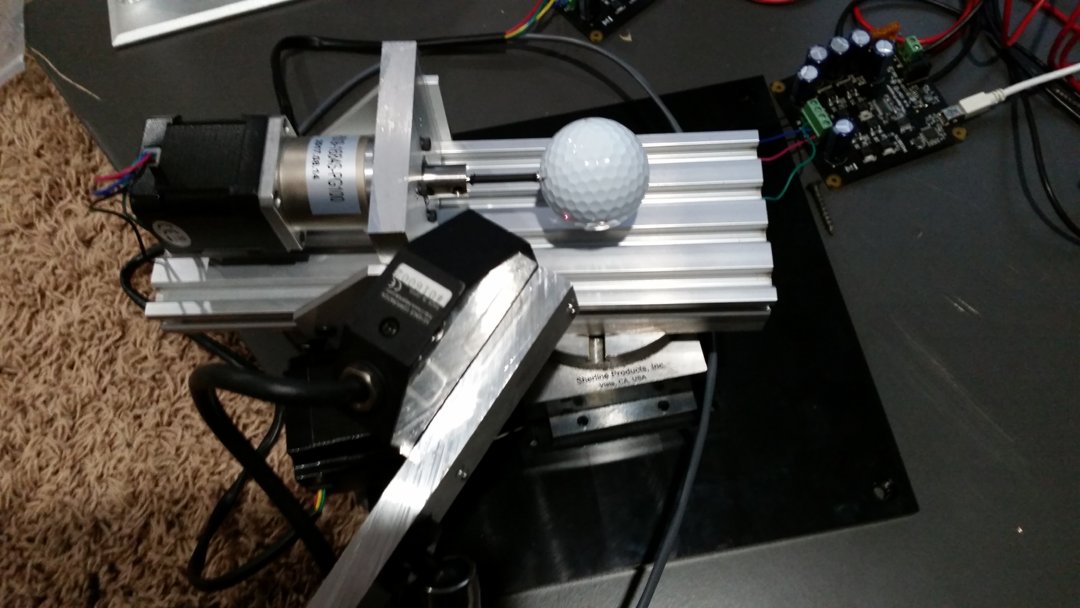
The first major revision was built around the cheapest, used laser sensor I could find with the highest accuracy. The Keyence LK-031 laser sensor can measure up to 10 mm of displacement. A standard golf ball has a radius of about 21 mm. To scan as much surface area as possible, it seemed the sensor would need to remain as close to a fixed distance from the surface as possible.
I had a method to mount a golf ball to a motor shaft based on a previous project. That would provide one axis of rotation. I also used Sherline CNC rotary tables in other projects and Sherline made a scanning platform to mount it to for stability. Using a CNC router I posted as another Open Builds project, I constructed two aluminum plates, one for mounting an Open Builds 20x80 mm rail to the rotary table and another for mounting the ball shaft stepper motor to that rail. The rail allowed some flexibility to align the center of the golf ball to the center of the rotary table axis. The next step was aligning the laser to the golf ball which was accomplished by a third aluminum plate and a SmallRig adjustable arm.
After the mechanics were worked out, the stepper motors were wired up to Phidgets bipolar stepper motor controllers. The laser head connects to a Keyence amplifier unit that produces an analog voltage proportional to the measured displacement. The voltage was sampled by a Phidgets ADC module connected to an LCD panel with analog inputs. All motor control and measurement was governed by a C# application running on a desktop PC.

The below picture shows the size of the laser spot on the golf ball.
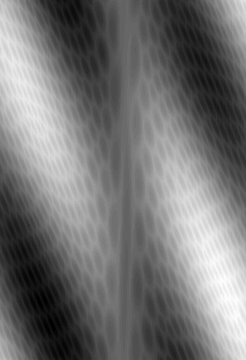
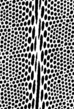
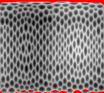
Below is the very first scan of the golf ball converted to a depth image:
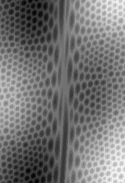
The number of steps per rotation was not quite right. This is the result after tweaking the scan data:
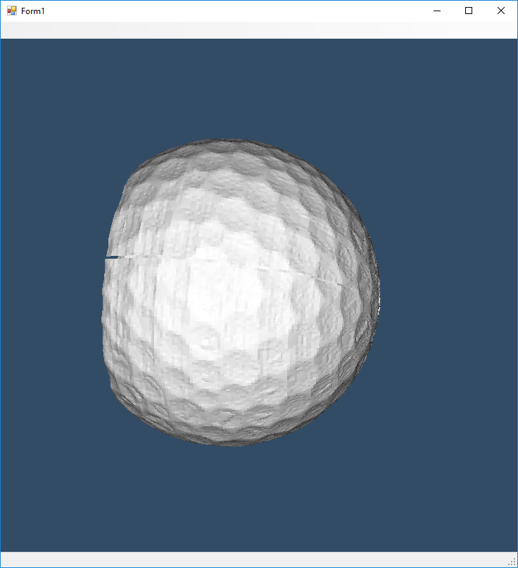
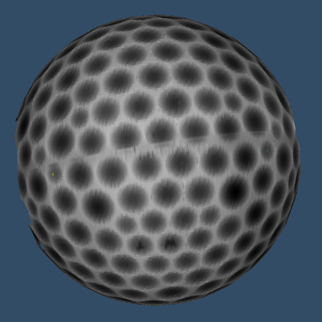
Mapping this into 3D coordinates, we get the following:
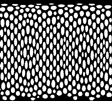
Since the goal is to find the center locations of all of the dimples, we apply some computer vision techniques. This is the result of using a localized thresholding algorithm:
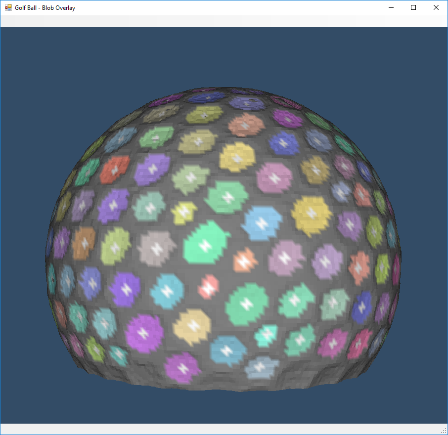
We then take the binarized image above and run a blob labeling algorithm. The average position of each blob pixel is calculated and overlayed as a white cross representing the dimple centers:

Applying this texture to the 3D point data gives the following:
The next challenge was trying to get a complete scan of the ball. This requires taking multiple scans of the golf ball in different orientations and merging them together. This proved to be incredibly difficult using the scan data from the version 1 scanner. There were too many assumptions about the physical alignment in the scanner to easily get the ground truth of the surface points.
Version 2
With reasonable results from the first approach, it seemed worth investing in another laser sensor that could measure larger displacements. This would incorporate the actual curve of the surface and thus have data which indicates the center of the golf ball relative to the dimples.
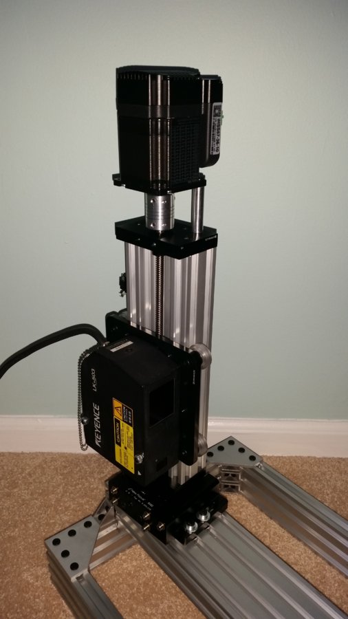
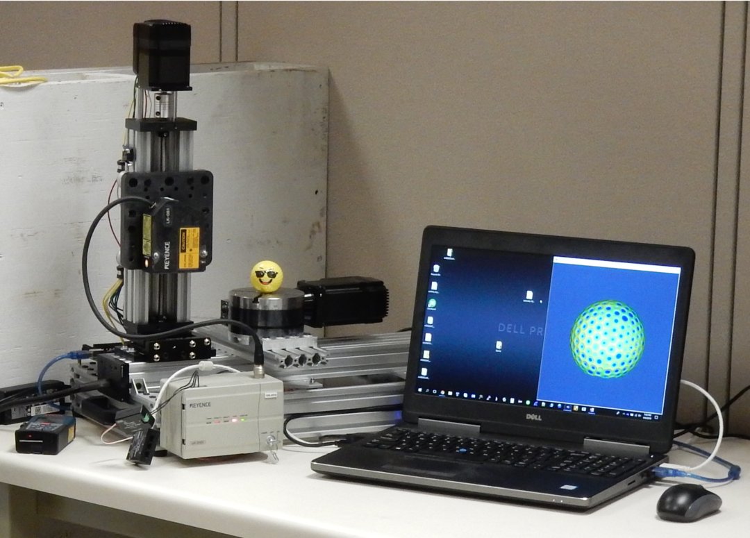
The second version mounts the laser sensor on an Open Builds linear actuator for the vertical axis. It is mounted to a base using a 5-axis optical alignment stage (with springs that were far too weak for the given load, but it was the strongest I could acquire/afford):
The same Sherline CNC rotary table was used as a turntable:
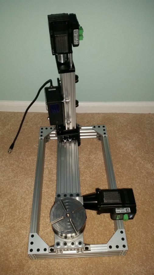
The open-loop stepper motors from version 1 were replaced with closed-loop stepper motors which could no longer use the Phidgets bipolar stepper motor controllers. The open-air circuit board in the below image is an Ocean Controls KTA-290 step and direction motor controller with ASCII interface over USB serial port:

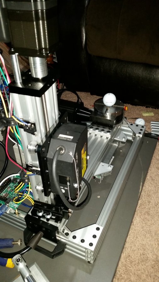
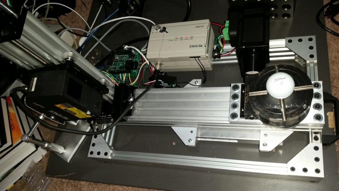
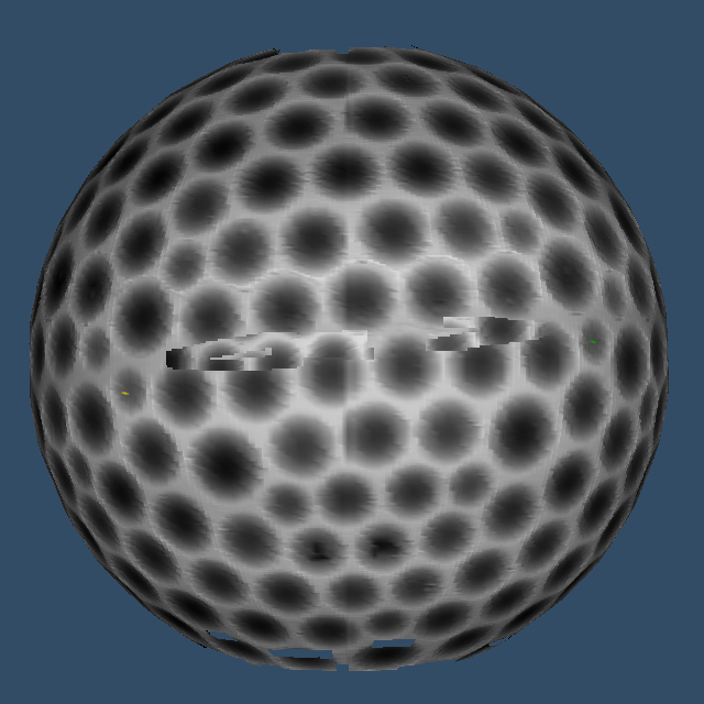
The large distance between the laser sensor and the golf ball is to satisfy the measuring range of the Keyence LK-503 which is centered at 350 mm with a +/- 100 mm range. The LK-503 is a class 2 laser which is safer to use than a more powerful class 3 laser sensor. Since I was spending significantly more for the laser sensor, I wanted a sensor that was as versatile as possible for future reuse. And here's why that was a bad idea:
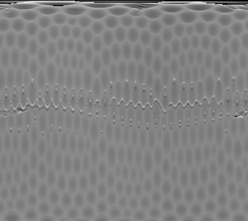
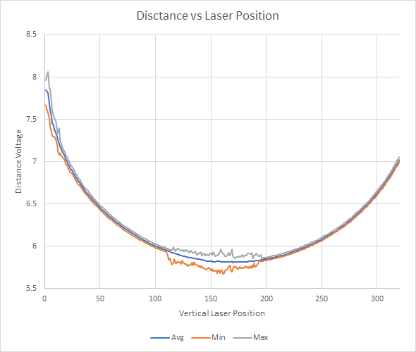
See the artifacts running along the equator in the above scan image? Here's a plot showing that in more detail:
I tried upgrading to the class 3 laser in case the laser point was too dim to triangulate properly. That didn't help much. Since I was committed to getting this to work at this point, I decided to sacrifice the general reuse of the laser sensor and select one for the intended measuring range. This led to the LK-081 which was back down to a class 2 laser and was the final iteration of the design:
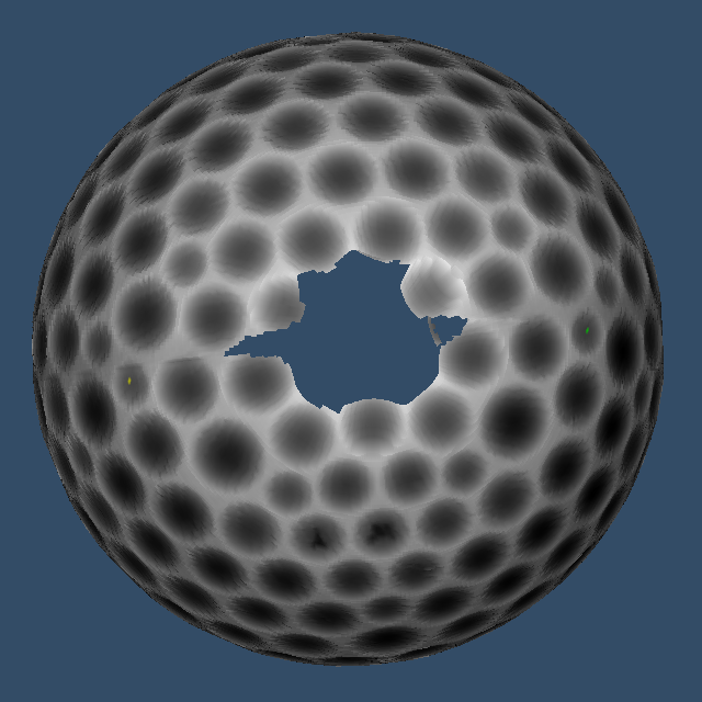
Here are the final scan results with manual masking to remove the errors at the top and bottom of the vertical range:
Applying the same local threshold as before:
The following are three plots of the same golf ball scanned at orientations that were roughly 90 degrees from each other. The depth image was used as a texture for coloring the points. Two dimples in each of the depth maps were marked with a yellow and green marker. A regression using a quaternion rotation model was performed to orient the golf balls the same way.
The next step which I have not yet completed is performing another regression using the scan data to more tightly align the individual scans into one complete scan. This was proving to be very computationally intensive.
As interesting as this project was, I am no longer working on the product that was motivating this effort so further progress is probably unlikely. I am posting the current state in hopes that it is interesting and informative to others. Let me know what you think!

Laser Displacement Golf Ball Scanner
Build in 'Turntable 3D Scanner' published by James Evanko, Jul 26, 2019.
Getting an accurate scan of a golf ball can be difficult with general-purpose 3D scanners. This purpose-built golf ball scanner uses a very accurate Keyence LK-081 laser displacement sensor with an Open Builds linear actuator for the vertical axis and a Sherline CNC rotary table for the turntable. Scan detail is determined by the sample step size and can be set arbitrarily based on desired scan time.
-
-
Build Author James Evanko, Find all builds by James Evanko
-
- Loading...
-
Build Details
- Build License:
-
- CC - Attribution - CC BY
Reason for this Build
Wanted an accurate way to extract 3D coordinates of golf ball dimples to form a template for identifying golf ball orientation in a computer vision application.