I have a very small workshop so have only space for one CNC machine, but it must do a lot. I could not find a machine design that would work for me, so have set about creating a compact machine that:
- Could be disassembled and packed away/moved quite easily if I really had to (i.e. stripped down and stowed in under an hour, and will fit in the back of a family car),
- had at least 1/4 sheet of machining area (i.e. 1250mm x 620mm minimum) with an open front/back so a full sheet could be processed in panels (I now know the design concept can go up to 1/2 sheet quite easily),
- can mill wood and aluminium with ease, and the occasional steel part,
- has a Z clearance that was large enough to skim the top (and cut bowties/ V-carve) of an 8” thick slice of tree, without having to dismantle the wasteboard/machine bed.
- has usefully fast travel moves (>5m/min, 10m/min or better on X would be awesome).
I have a small CNC at the moment, but it would also be good if any bespoke component parts of the design could be easily hand cut, or CNC cut from plywood on a 3018 machine to a standard that would allow the machine to bootstrap-cut its own aluminium parts.
After much experimentation, I have concocted a design that is modular and based on ‘C-Beam actuators’, but the beams are constructed rather than made from a single extruded section, and are made from 8-series 4080 channel, HG20 linear rails and ball screws. Although not a cheap option, it satisfies all my criteria, and is plenty strong enough to throw around a 2.2 or 3kW water-cooled spindle.
The other critical design feature that gives the rigidity to cut aluminium easily, but also provides a huge Z clearance when processing thick slabs of wood, is to configure the machine as a dual-Z XYYZZ structure. My small workshop relies on having the bench under the CNC as storage, so making an adjustable machine bed with variable height is less convenient. I use FluidNC with external stepper drivers to run my current CNC so realised having a dual Z as well as a dual Y configuration was no problem, and the Z would benefit from the same auto squaring as I have on the Y axis of my current machine (i.e. all true separate drives and no 'ganging' of steppers needed). Although rigidity can be a problem with moving-gantry dual-Z designs, the use of dual 4080 channels to form the ‘C’ works well enough, and the ball screws and properly rated motors mean there is no risk of lost steps.
The key to making the design work, is that the constructed C-beams use sections of OpenBuilds 5-series 4080 C-Beam extrusion as the ‘webbing’ that acts to support the ball screws, and hold the main rails into a ‘C-beam’.
There are a few compromises that I have had to accept. The first is that for the most compact configuration, the Y-axis motors have to hang under the work surface (not a problem as I am yet to build the bench), or they can go out sideways in an alternate, and more rigid configuration, but it takes more space. The second compromise is as the entire gantry moves up and down, a vacuum chip-extraction attachment cannot be at a fixed height, and must either float, or go up/down with the spindle. Neither are show-stoppers for me.
The machine I am building uses a 1500mm 2010 ballscrew on X, 1000mm 2010 ballscrews on the Y axes, and 450mm 1605 ballscrews on the Z's. The X and Y axes use 8.4Nm closed-loop Nema34's, and the Z axes use 4.8Nm closed-loop Nema34's. All the axes use 20mm linear rails with 4-blocks per axis. I am mounting a water-cooled 3kW VFD controlled spindle as the main unit, and have a second relay output for running a router as a second spindle in a horizontal orientation. The machine can also be fitted with a 10W diode laser, has M7/M8 controlled airlines, and an optional rotary axis (currently running just 'A', but has lines for a 'B' channel option in the future).
The working envelope is an X span of 1320mm, 820mm in Y and 300mm in Z. After the initial experiments, it looks like it may be possible to run the X with a rapid speed of 15m per min, the Y's at 8 to 10m/min and the Z at about 5m per min.
In true 'prototype' fashion, the design changed a few times along the way, and I have actually ended up with the parts for a second machine as well that is based on open-loop Nema23's and has a 2.2kW spindle made from the bits I had left over ..... It may not move about quite so quick but is simpler to make! I just need a bigger workshop now")
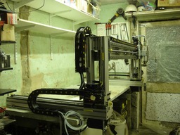
"Hawk" Heavy-duty dual-Z pseudo C-Beam
Build in 'Other Style CNC Mills' published by EvanH, Feb 28, 2024.
A compact, strong machine with very high Z clearance, yet can still mill aluminium easily.
-
-
Build Author EvanH, Find all builds by EvanH
-
- Loading...
-
Build Details
- Build License:
-
- CC - Attribution NonCommercial - Share Alike - CC BY NC SA
Reason for this Build
I could not find a machine that was powerful enough to machine all my projects, yet small enough to fit in my workshop.Inspired by
Gantry on my Creality 3D printer, LowRider, Gooshpoo's H style cnc machine and Openbuilds 4x8 cnc by Sam Keller -
Attached Files:
-


