
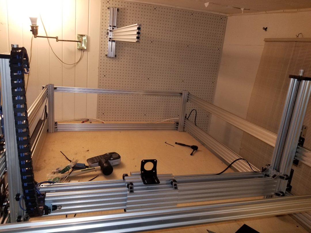
I really had no plan on documenting this build mostly because I had no real plan. All I knew was what I wanted.
It had to be big i ended up choosing 1000mm x 1500mm x 800.
I wanted to do everything 3d printing, routing, aluminum milling, lazer engraving.
And I wanted it to be fun.
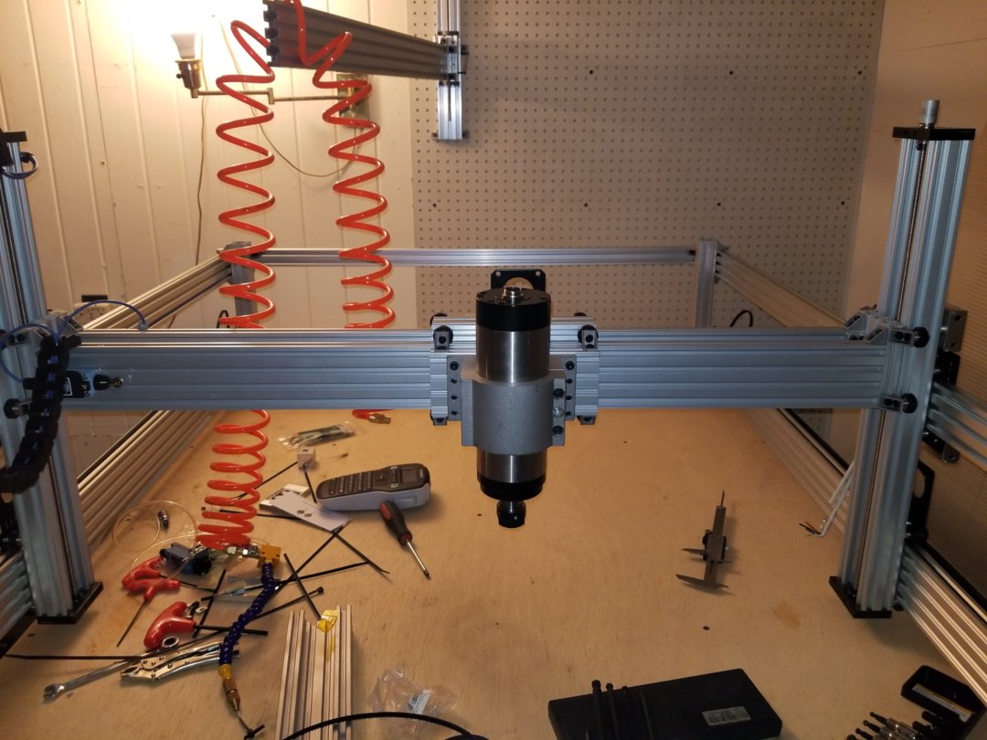
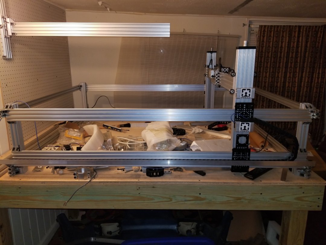
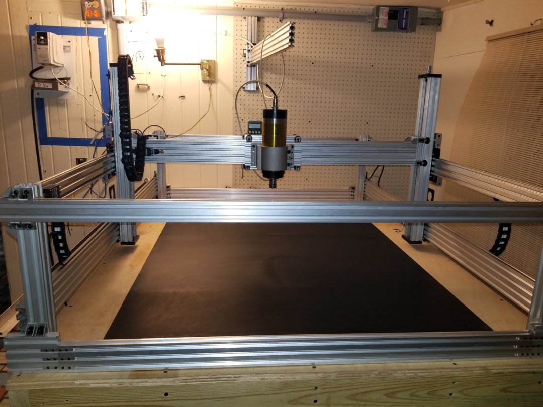
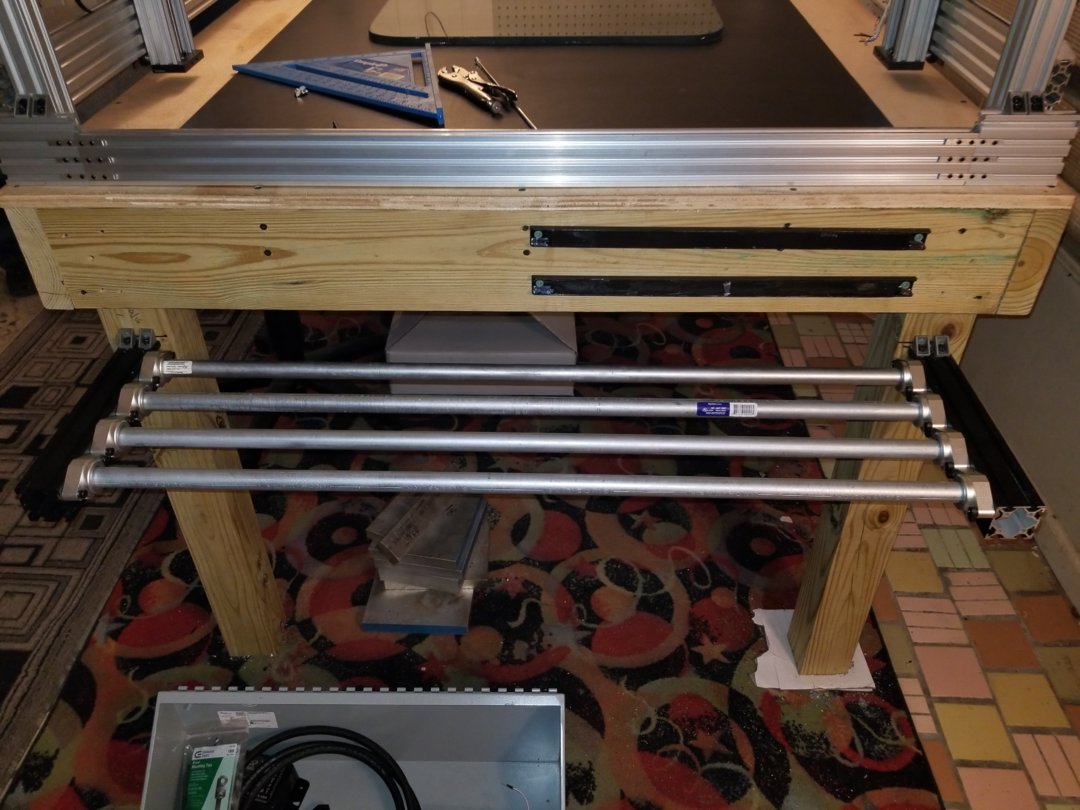
So i begun the work by trying different rail set ups. The reason i went with the dual rails was for pure stability. Wanting to do 3d printing i wanted to have more then a couple inches of z.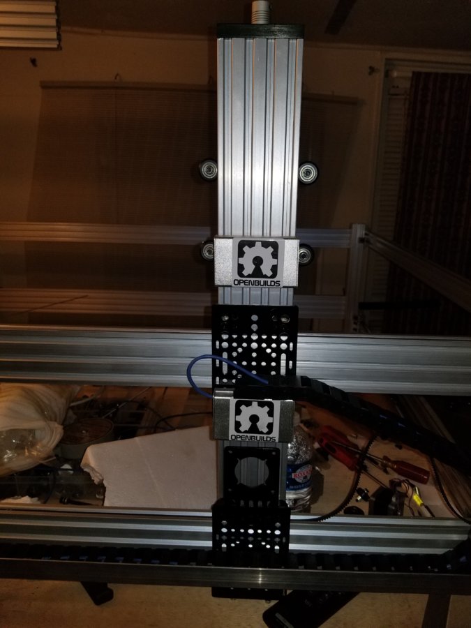
I used c beam for my z legs using 8mm lead screws. On both sides to drive the gantry up and down.
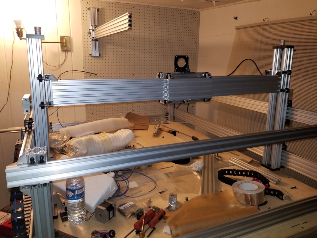
Everything else is using gt3 belts and i intend to use nema 23s or bigger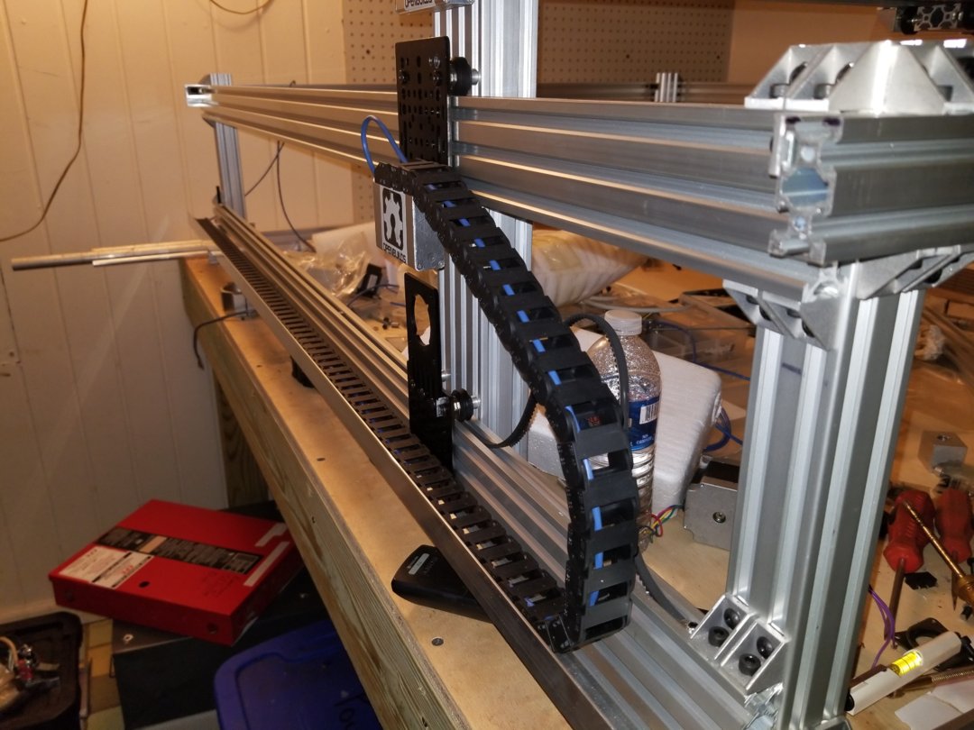
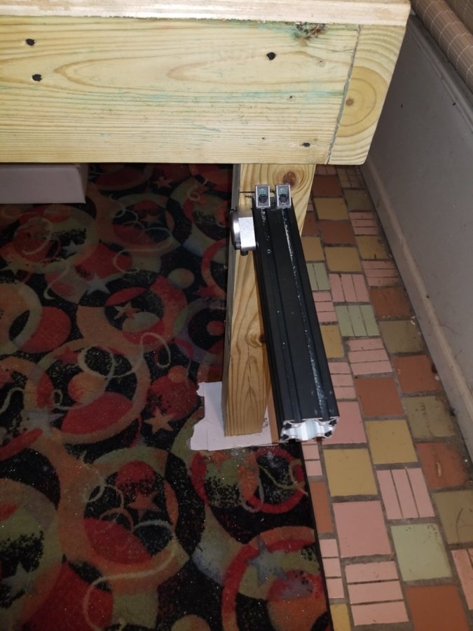
The rail hanging from the wall is going to carry all the cable and tubing for the gantry
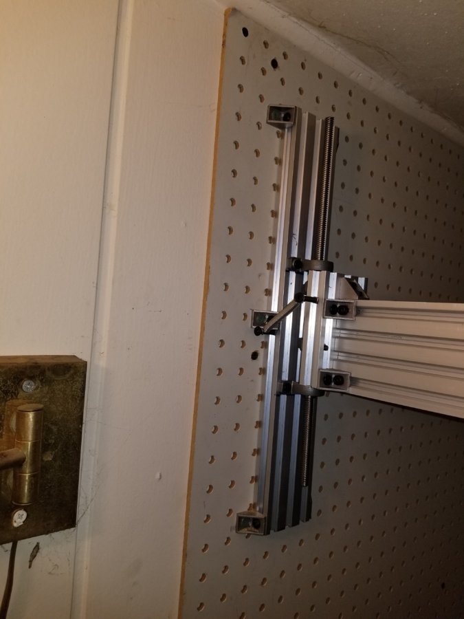
It can sway and there will be a small slide on the rail.
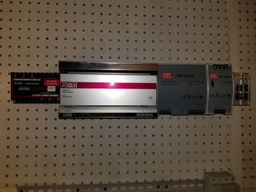
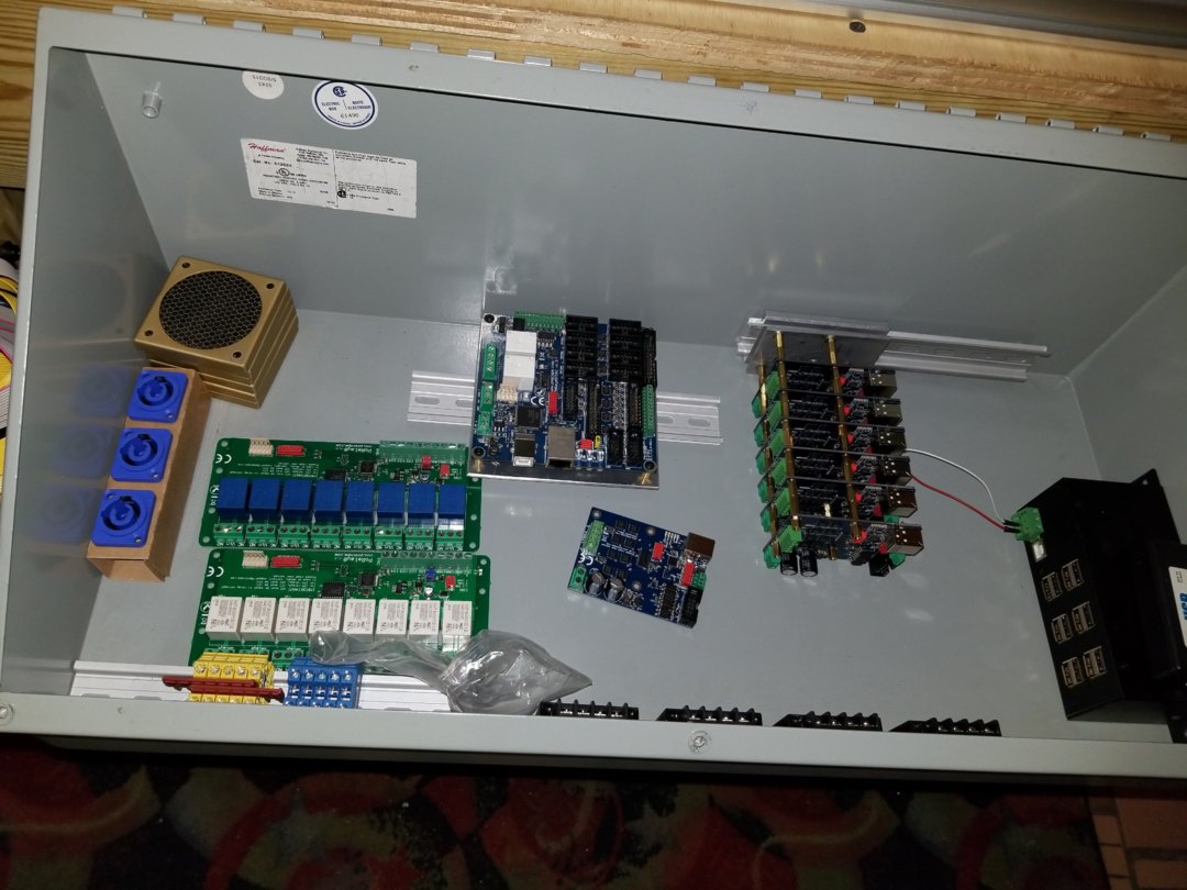
The electrical is planned with multiple metal boxes and break outs. Here are some pictures , keep in mind im still lacking the majority of electronics.
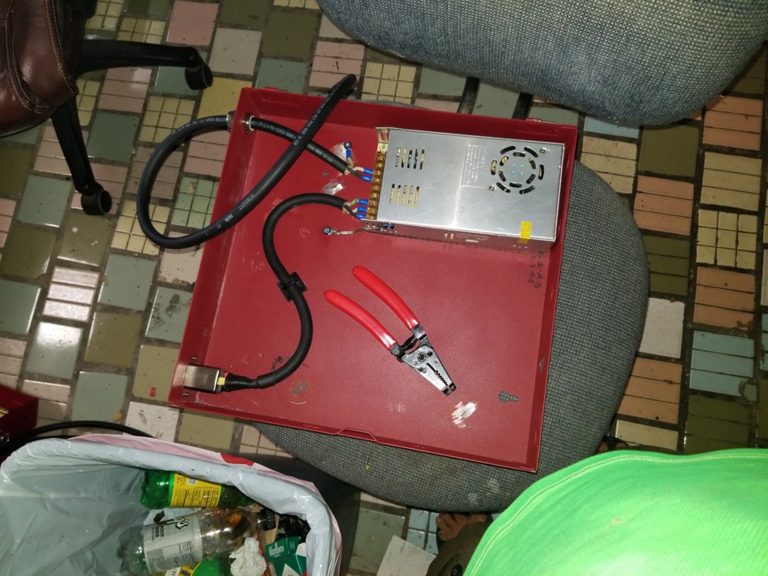
Herr is a 12v power supply with a ac line filter on it.
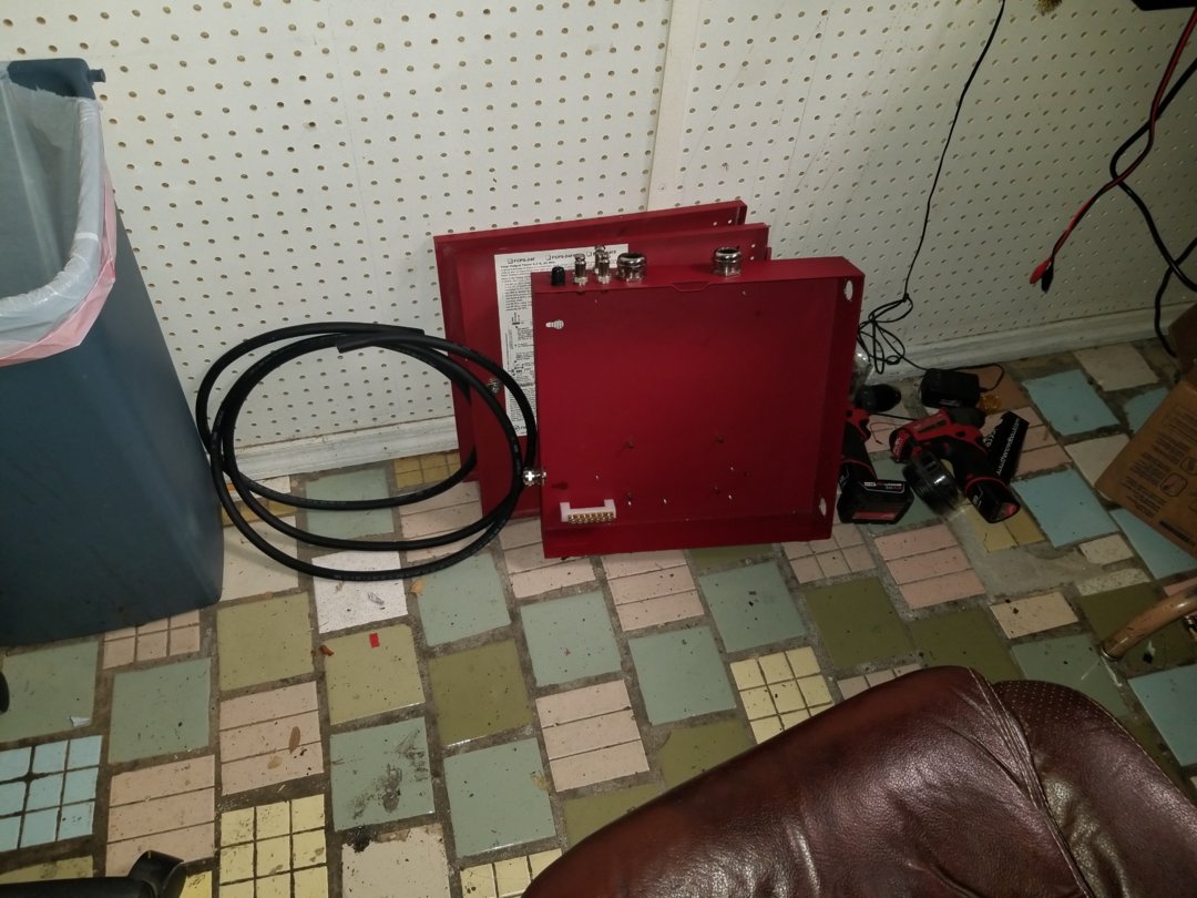
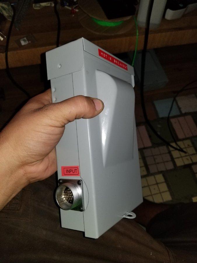
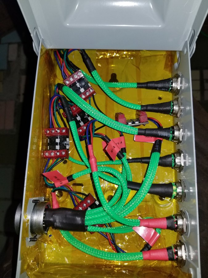
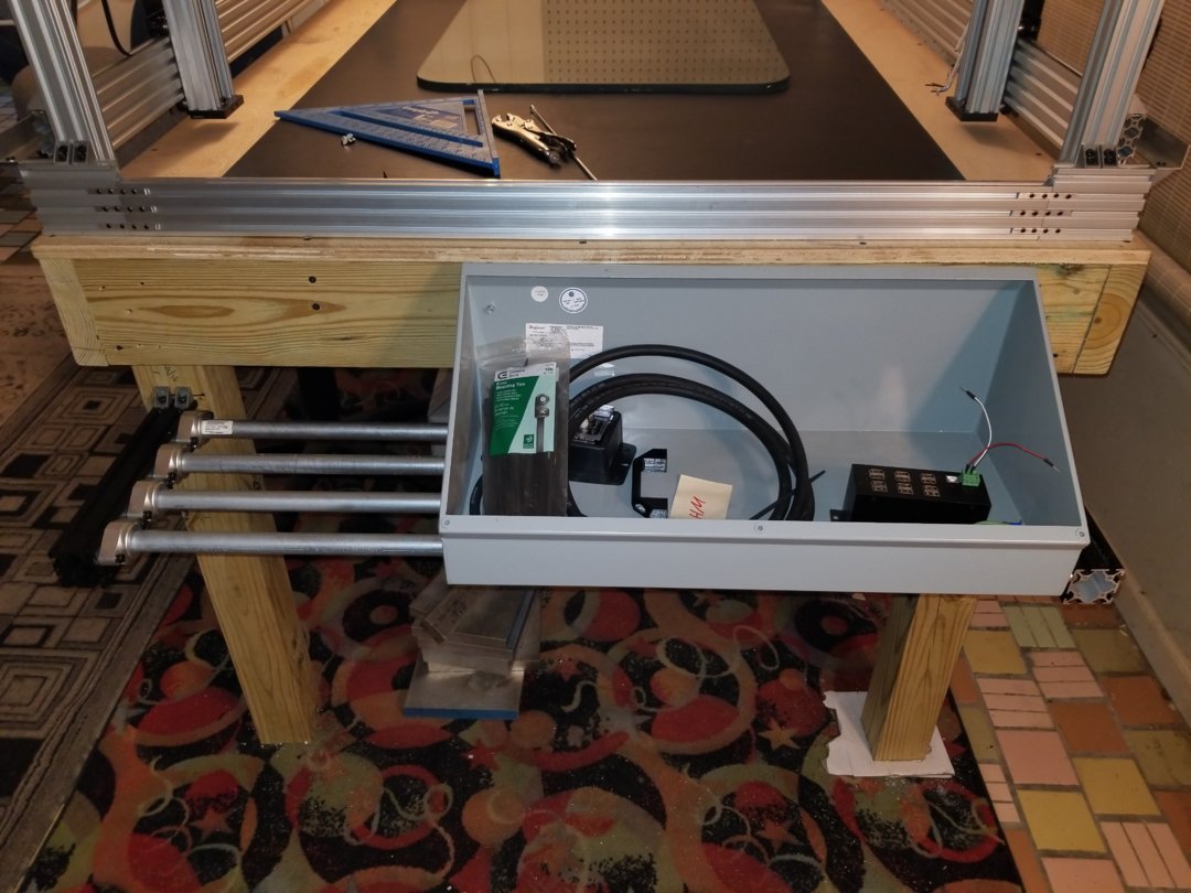
This is my main box it will hold the brain board that will break out into my motor and endstop boxes.
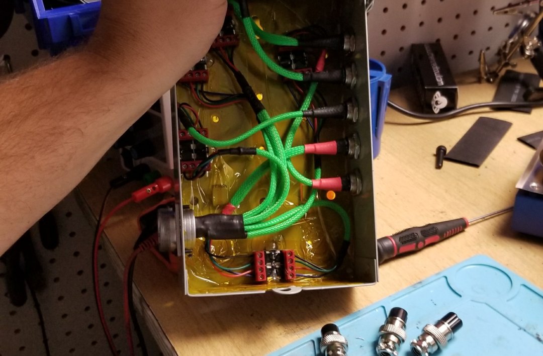
A 24 pin plug will come into the box then run into barrier diodes break out to the motors everything is shielded and grounded. Here is the 24 pin cable.
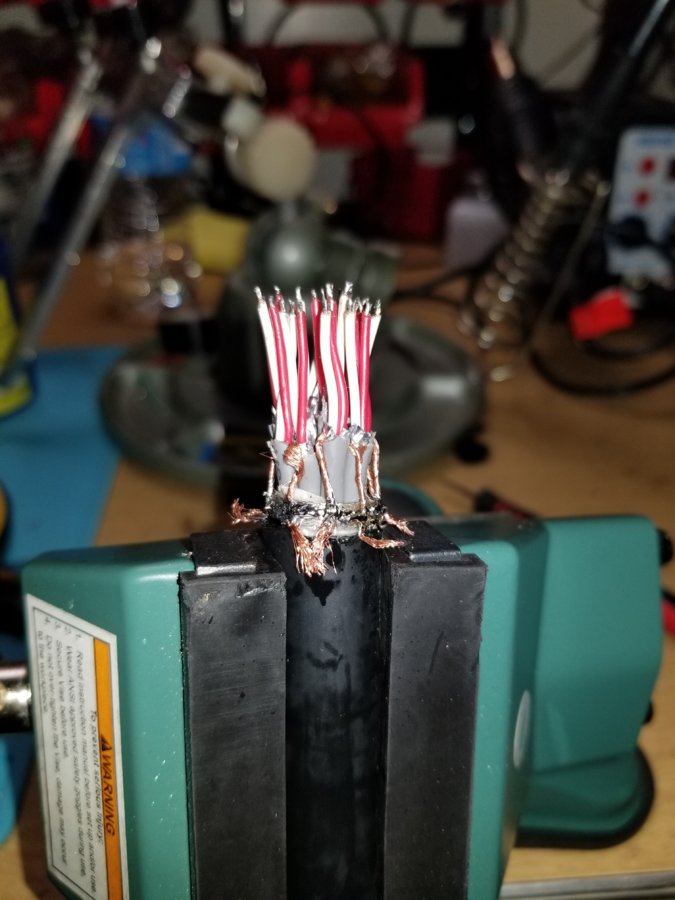
I stripped and pulled back the grounds and used some braided copper to connect them.
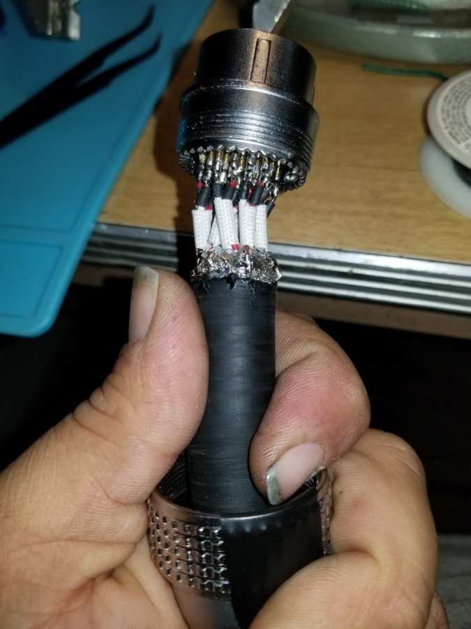
I put heat resistan sleave on each set of 2 as well as heat shrink. Then soldered them to the plug.
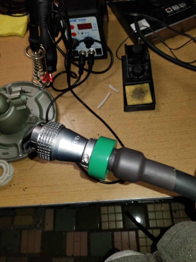
I put a large ferrite core around then end for extra protection. After wrapping electrical tape to make a stop i put heat shrink over it.
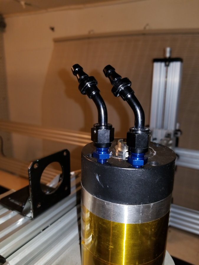
I have a 2.2kw spindle but without 220v i have to run it witch will be in the future.
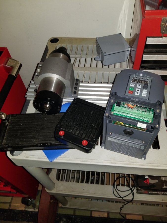
Im going to try a pc water cooling system for the spindle.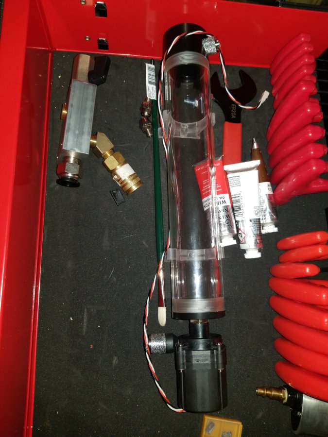
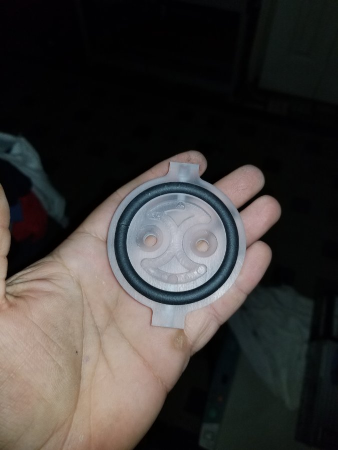
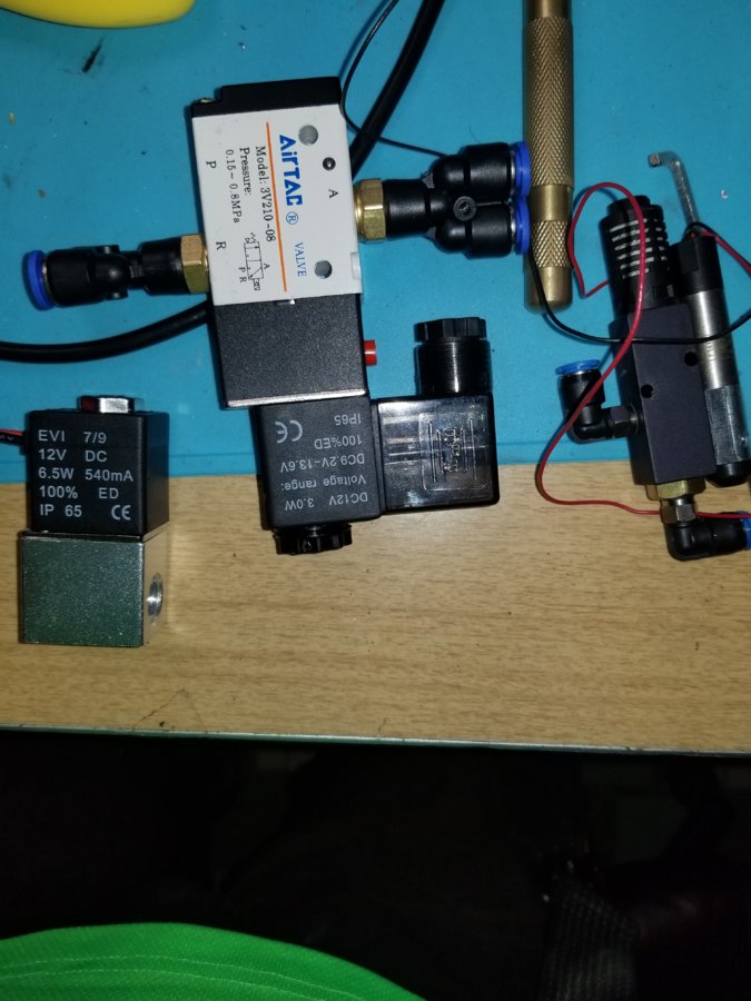
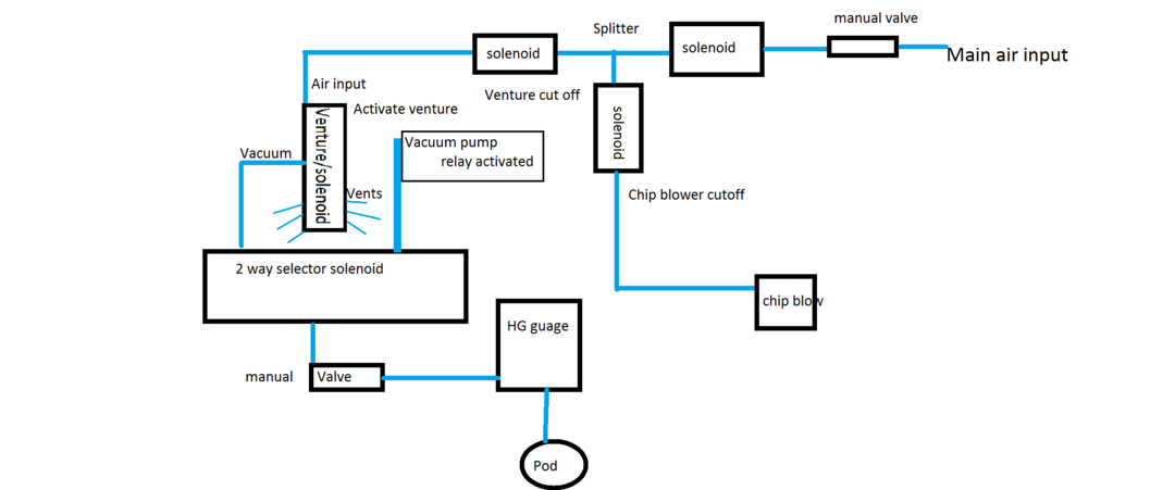
I have a vacuum pump and a air venture for a vacume table system that im building here id a vacuume pad as well as my selenoids
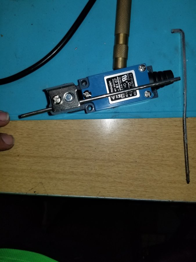
And the endstops i chose
The end stop box will be alot like the motor box just with opto couples instead of diodes.
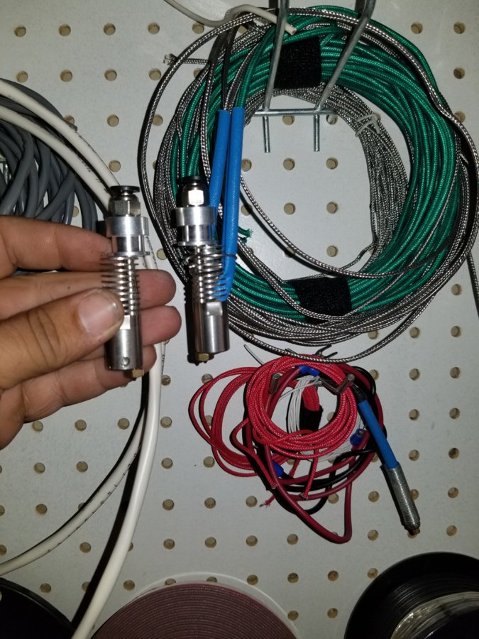
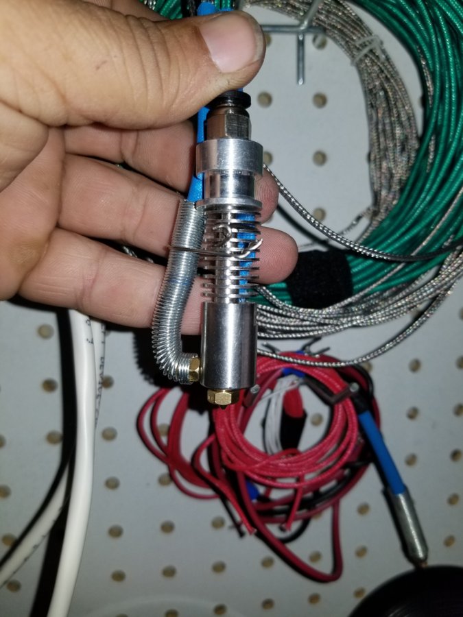
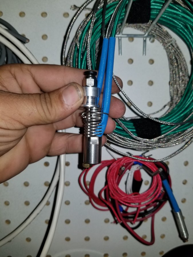
This is a few pictures of my hotends for when i 3d print.
This is all i can really think about right now. If anyone has questions please ask.
OK so Ive gotten a little more done. installed 3 limit/homing switches onto the Gantry. I then remembered that I only have 1 nut on each side, so I dismantled the gantry to install the other nut witch I'm in the process of now. here are some more pictures of what I'm doing. please ask anything you wish.
This is the prep for the wires for the limit switches.
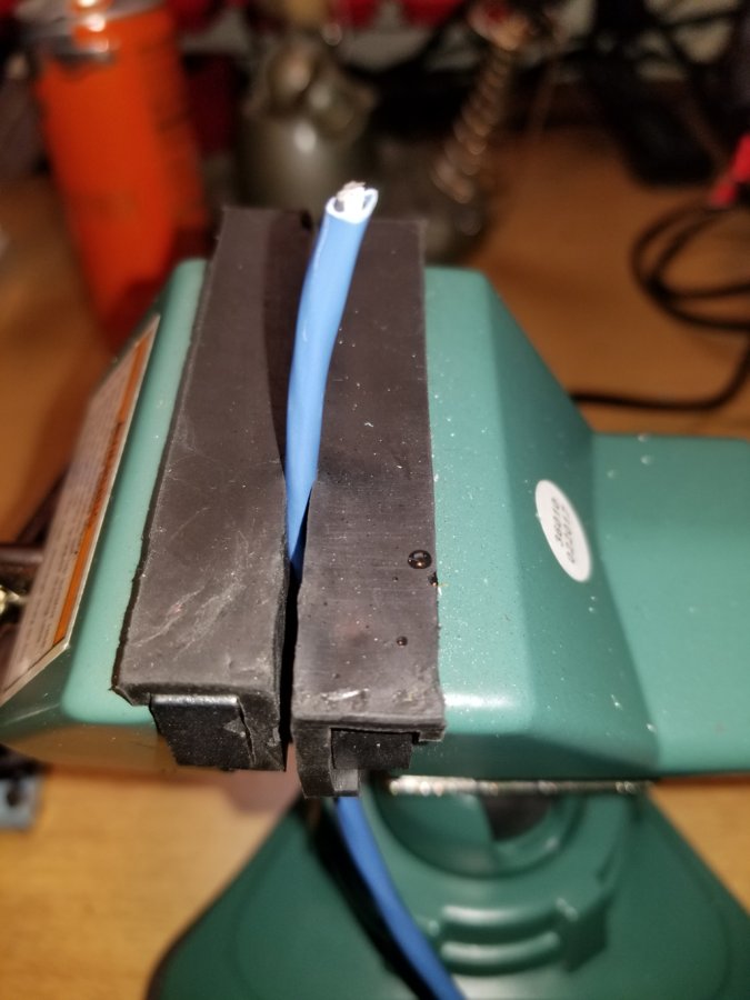
after cutting the jacket make a horizontal cut around the base and peel the jacket off.
make a vertical cut along the shielding, peel it to the side and trim the shield and the string if you have it. but leave the ground in place.
strip the ends and the ground a little , add liquid flux apply solder to your iron. I use a Youyue rework station it was around 60 bucks. and i run it at 400. Dab the soldering iron to the tips of the wire this shouldnt take more then a second or two for the solder to soak into the wire. do the same for the ground wire but run it up and down the majority of the exposed area.
im only using 2 wires and the ground so I left the white wire as is.
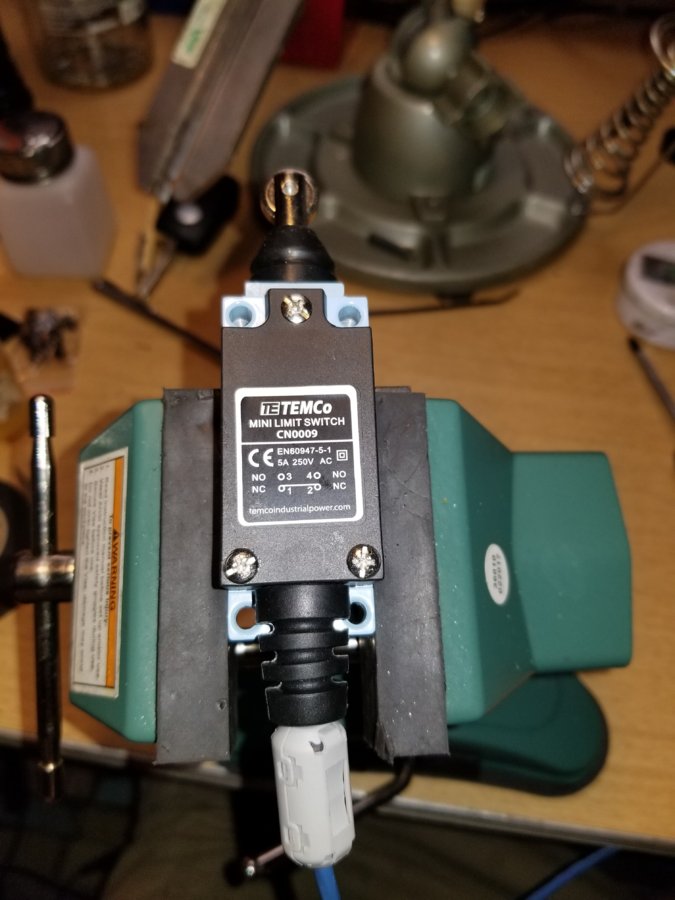
here is a finished switch lets take a quick look inside.
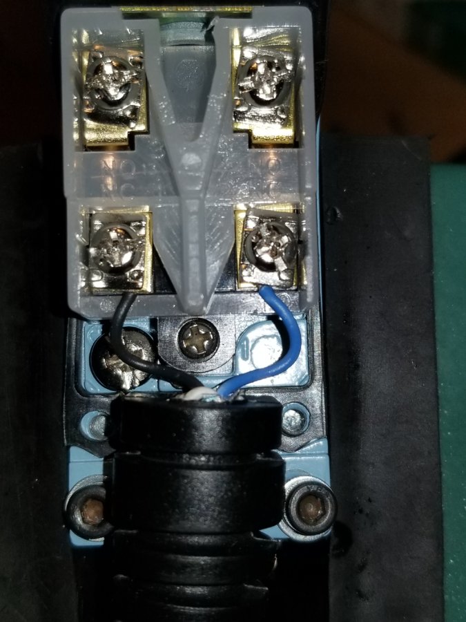
Here you see I how everything is wired the black and blue are going to the NC pins. Do this according to the electronics your going to use. but it is easily changed if you need to. connect the bare ground wire to the ground screw on the bottom left side.
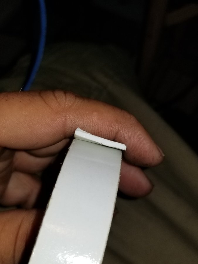
I used some super cheap double sided foam tape, i did leave the separator film on the tape for this. wrapped it around the wire and slid the black rubber sleeve over it. i did this to fill the hole left by using a smaller wire. it will help keep debris out of my switch.
Then as you see in the completed switch above i put a ferrite core on the wire for extra protection.
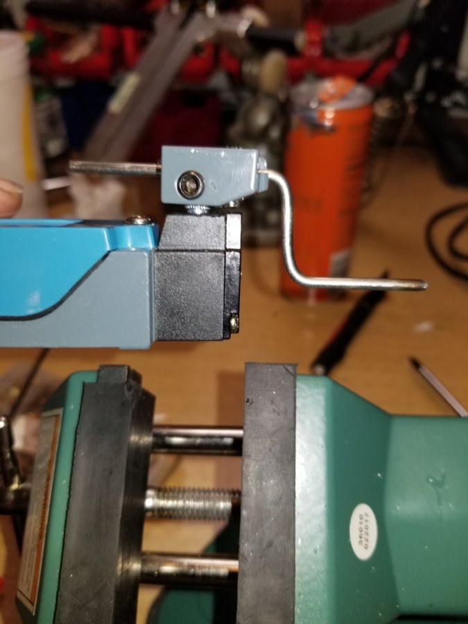
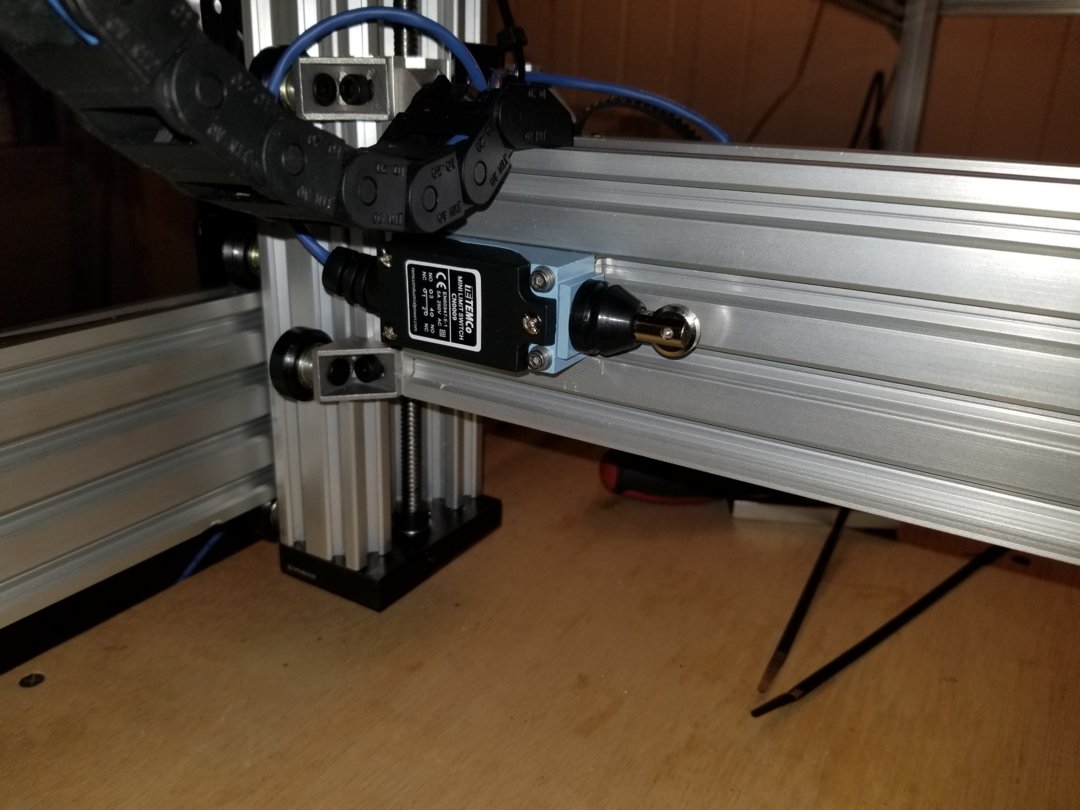
I used 2 plunger styles and 1 level style. for the lever style I bent the metal rod so it would be closer to my rail.
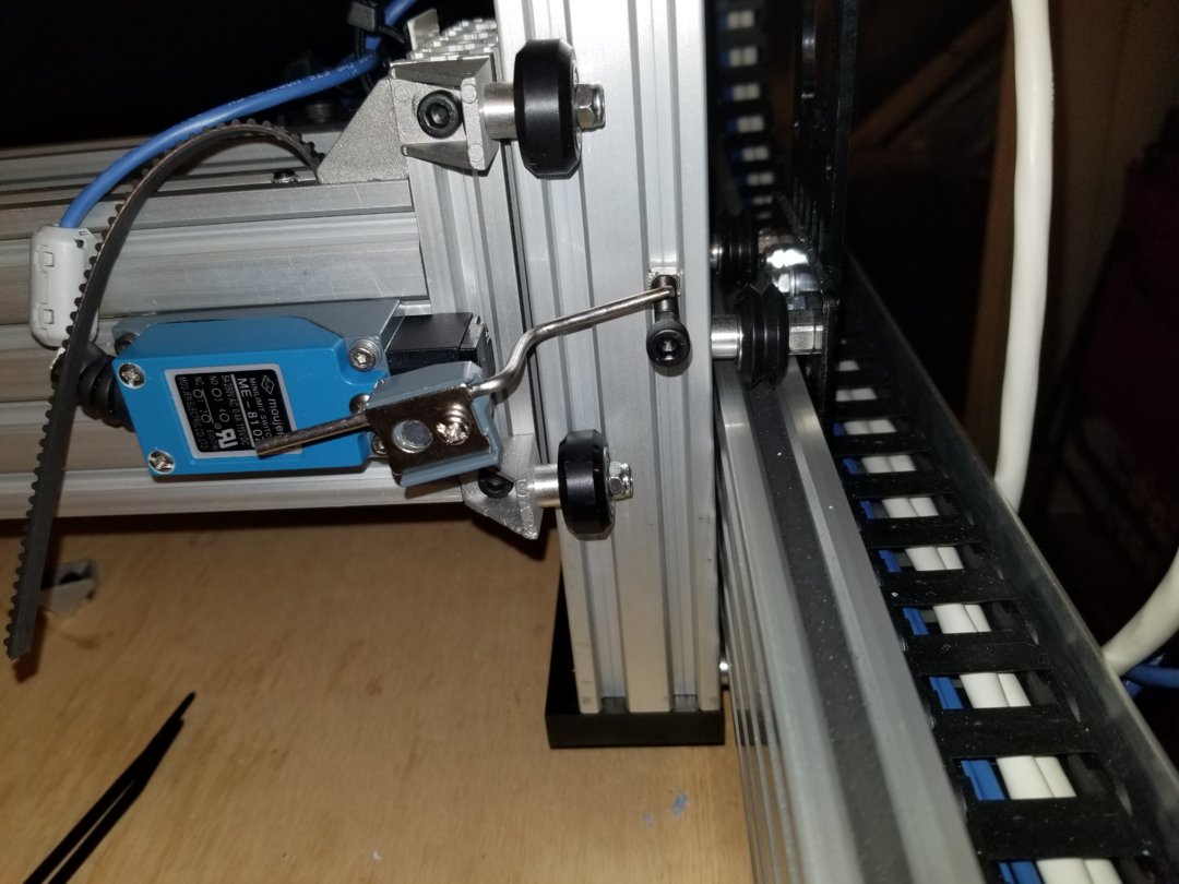
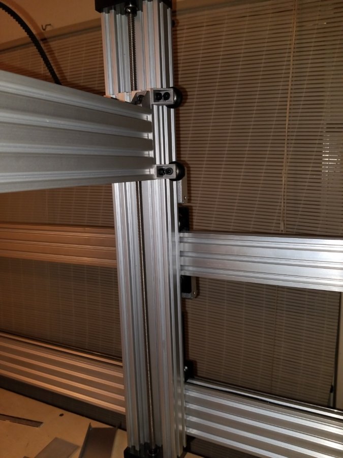
I made a bracket to attach cable chain to try and use it vertically.
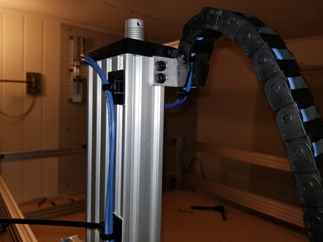
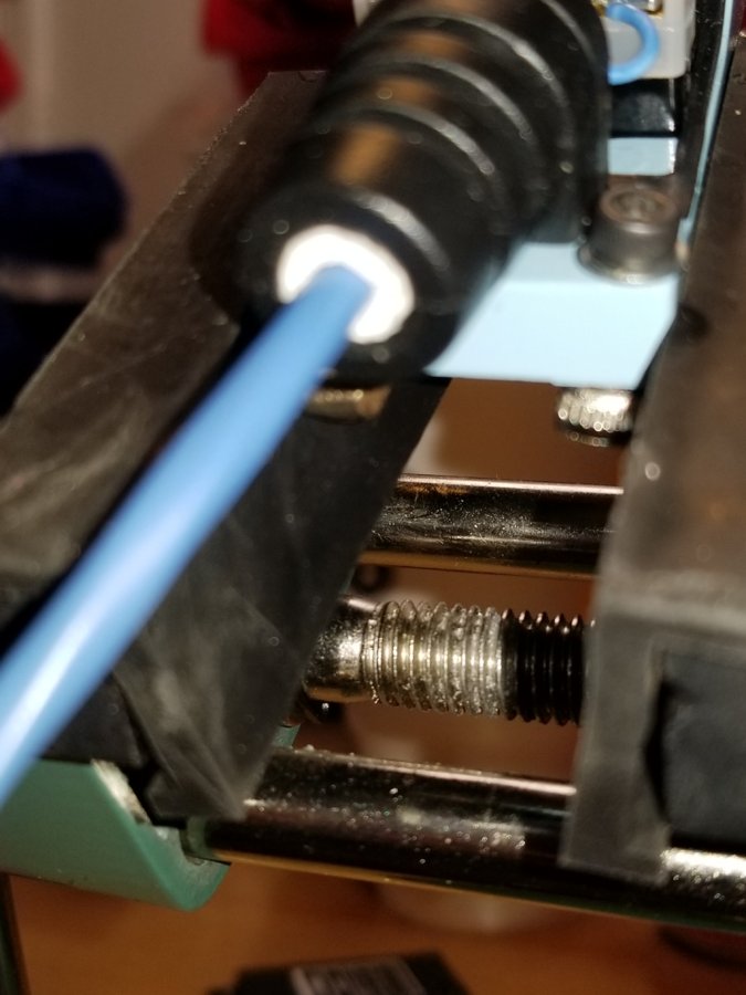
Here you can see the gantry in a low position with the chain extended as well as the position of 2 limit switches.
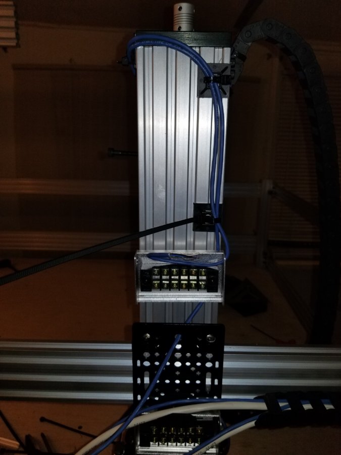
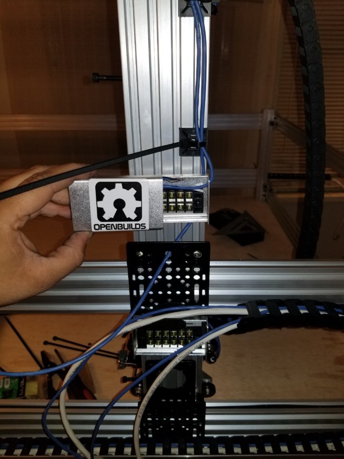
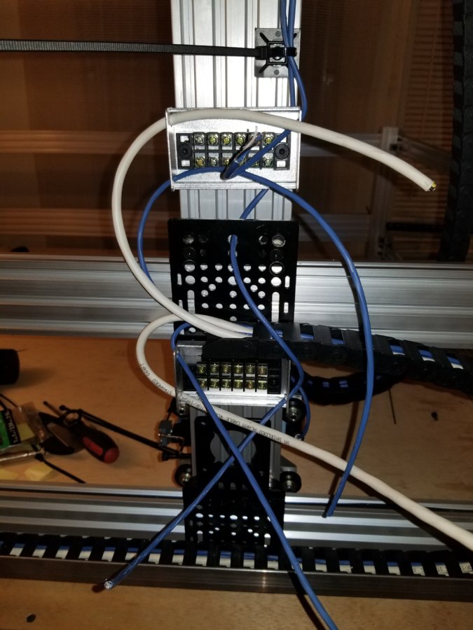
Im using screw terminals inside grounded aluminum boxes. Im hoping this will provide enough shielding to have a terminal right here for ease of motor changing.
So after doing all this I realized i have to take it apart to put the second nuts on here are a few pictures of that going on.
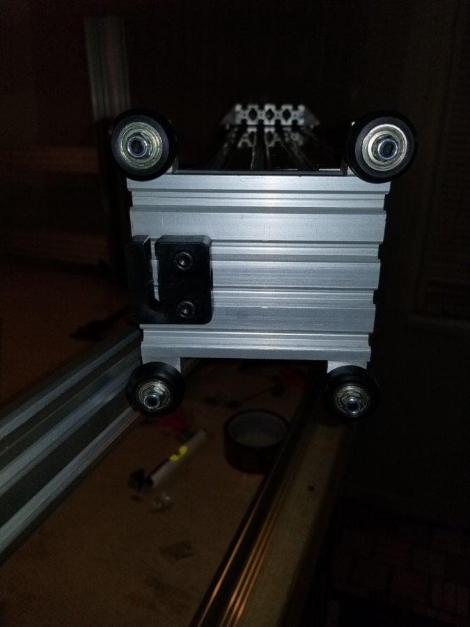
Im still in the middle of this. but here are some internals of the gantry.
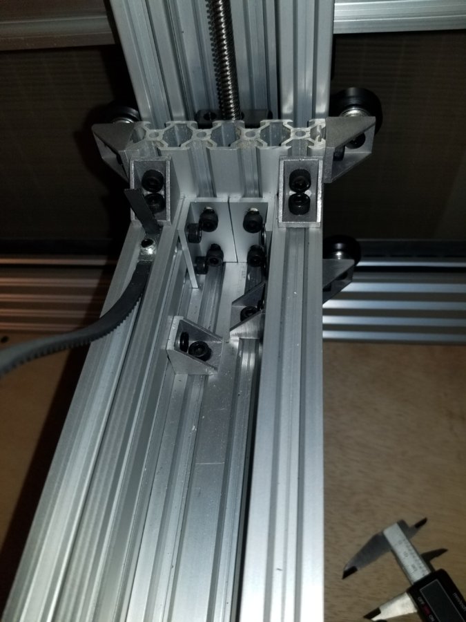
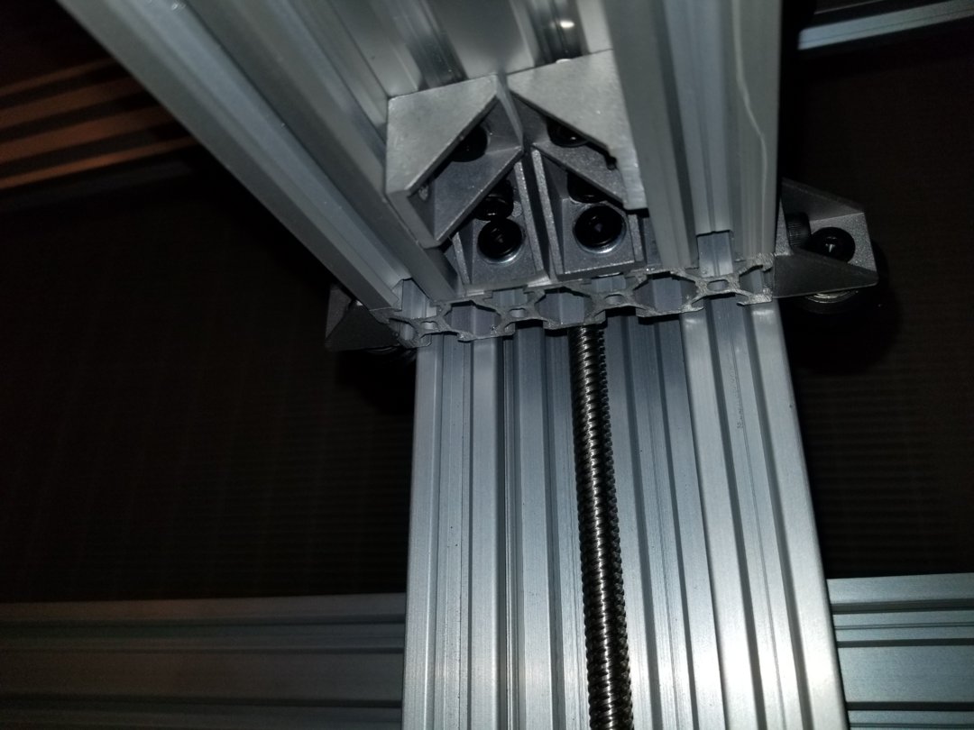
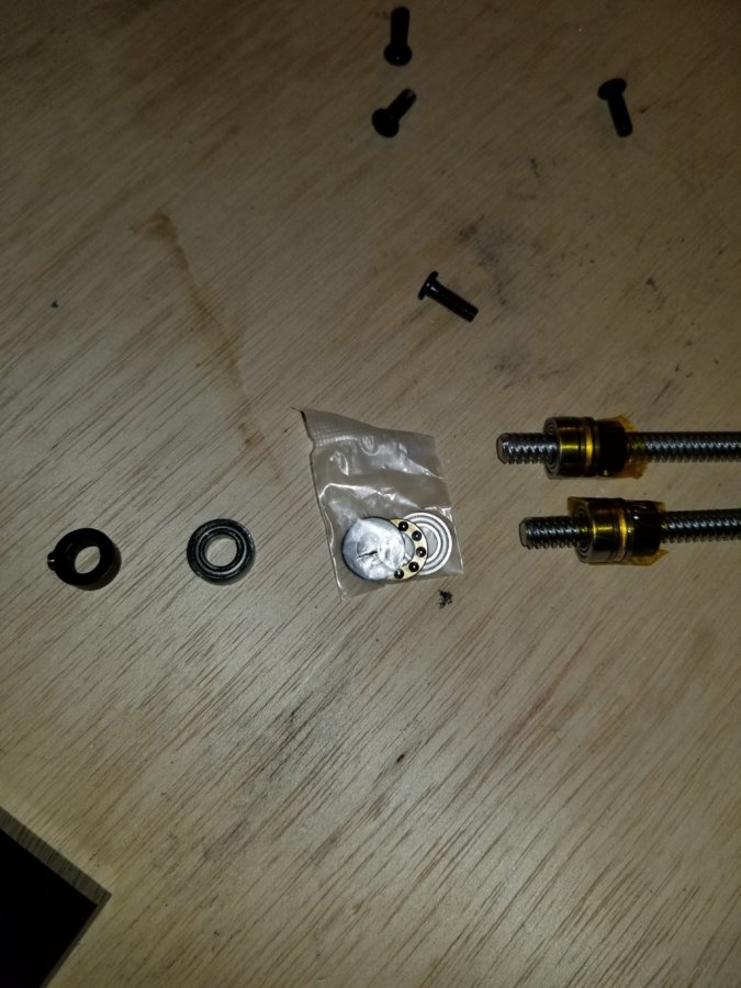
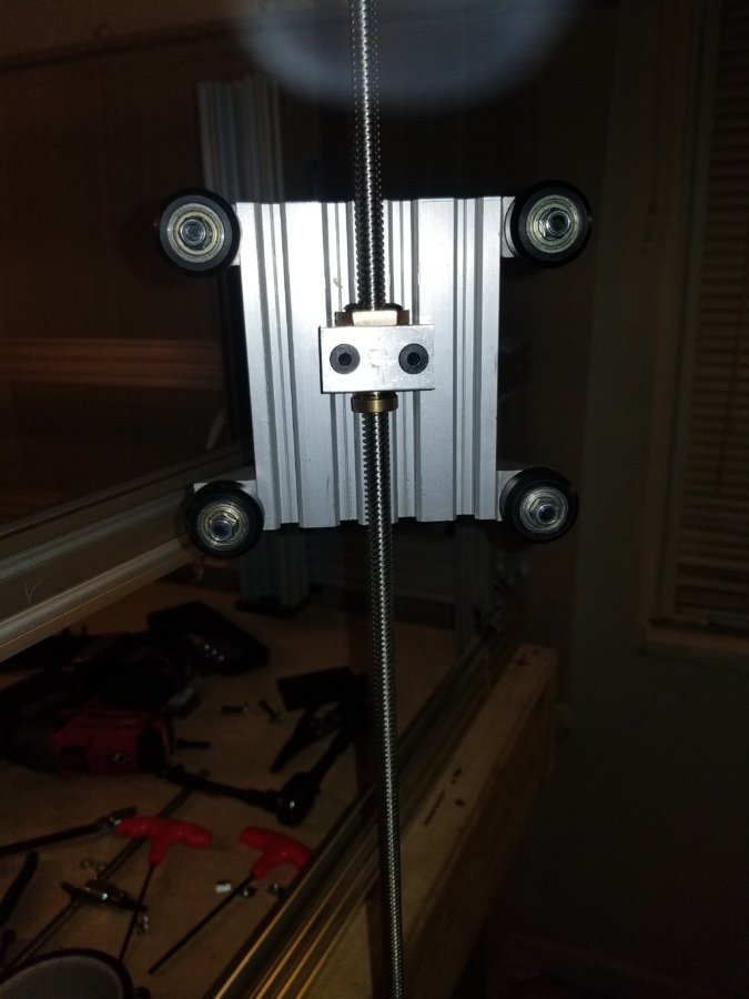
Im using your typical bearing for c beam as well as a thrust bearing to help hold the load with a lock ring on top.
Use some tape to hold it all together wile you insert them.
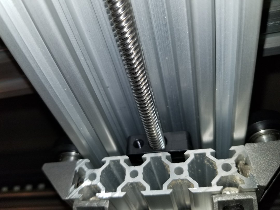
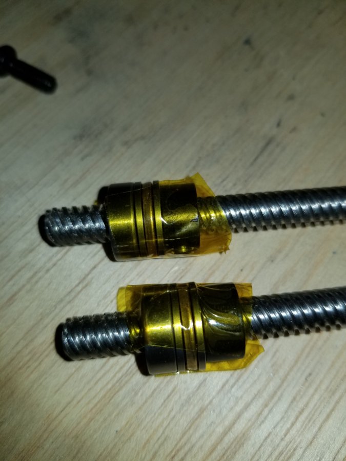
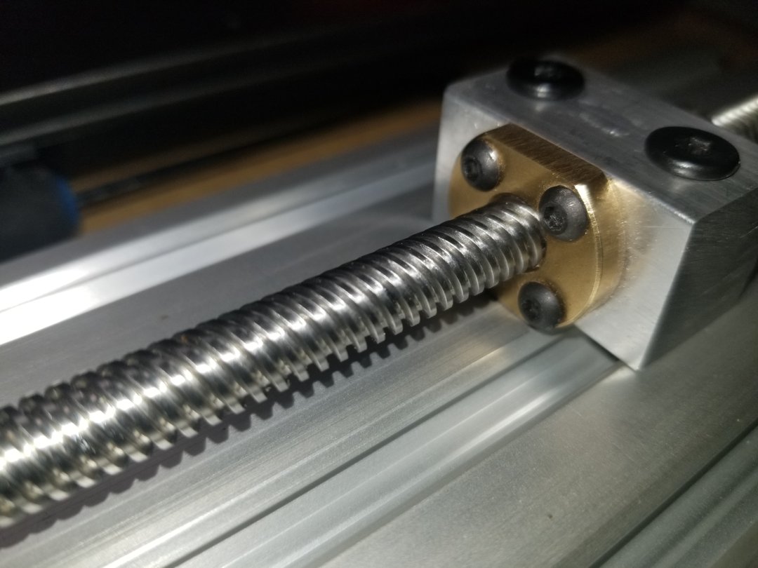
And this is where im adding a second nut. I do want to make some metal brass nut holders eventually but this will work for now.
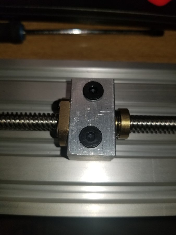
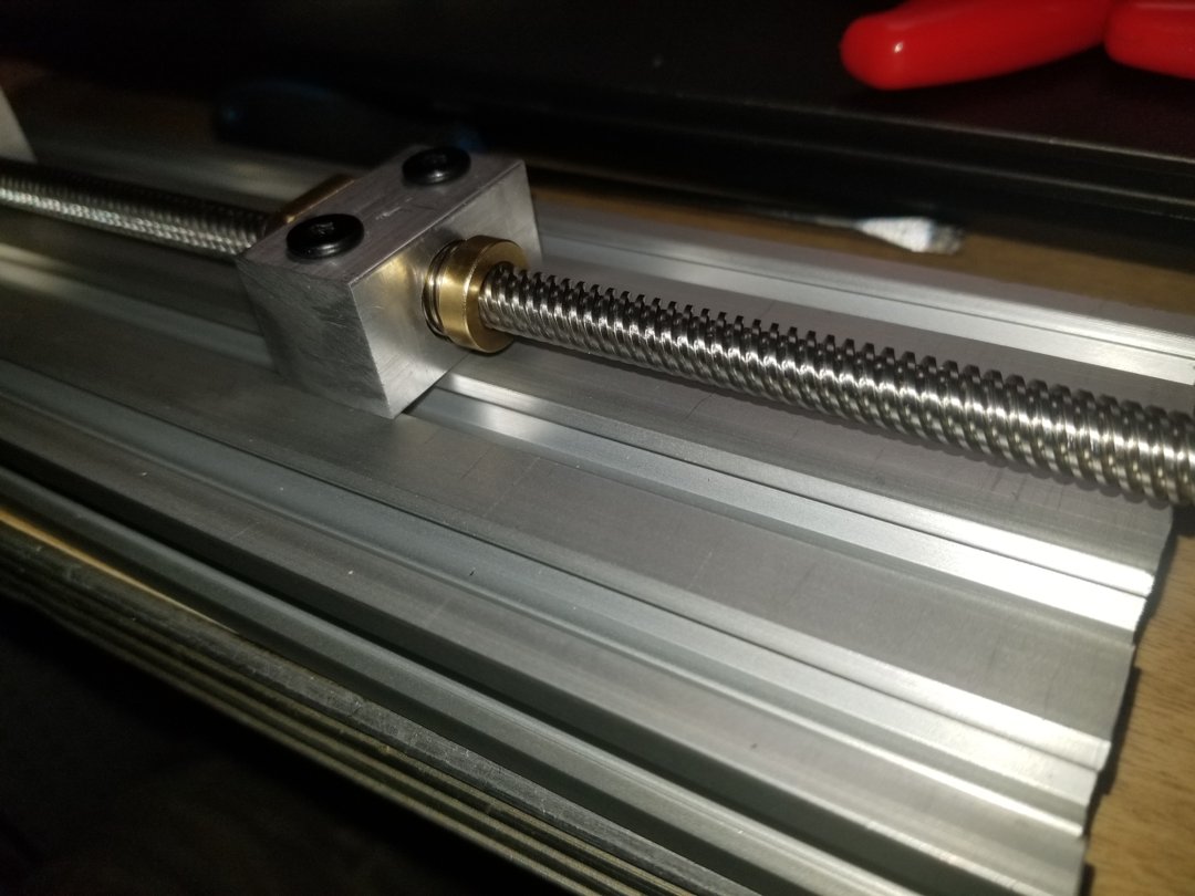
Ok well after checking it out playing with it a little i decided that the plastic nuts just will not cut it. so i made some metal brass nut holders and i installed them.
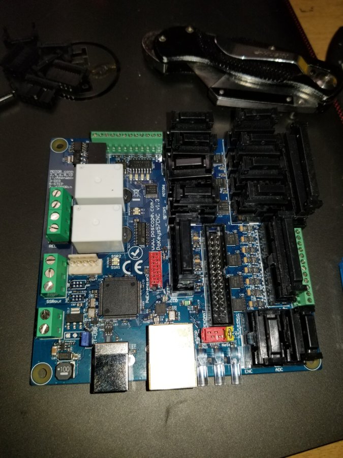
Well after much deliberation my friend the internet talked me out of using my smoothieboard for this project and instead use the pokeys 57cnc
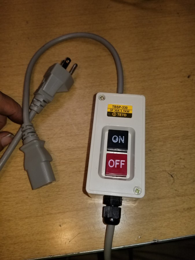
i did get a on off power cable made for my power box
this is all i have to update on this build right now i hope i get some time this weekend to play with my pokey.
So I got the 240v ran today but it looks like my fears have come true my spindle was damaged in the shipping the plug is all jammed in i told the seller i would try it first before trying to get a replacement. looks like im going to need one.
here are some pics
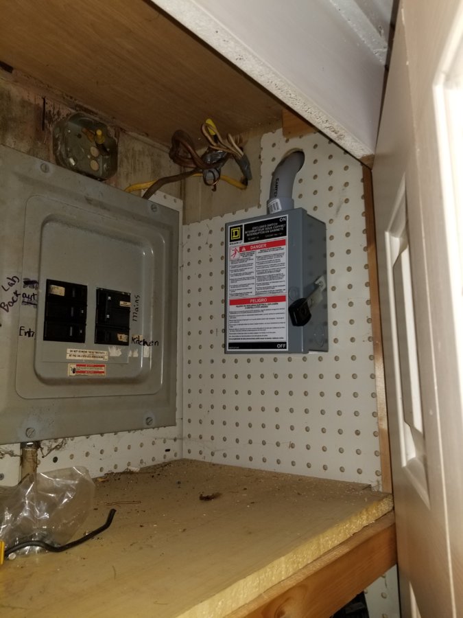
this is inside a closet by the main breaker
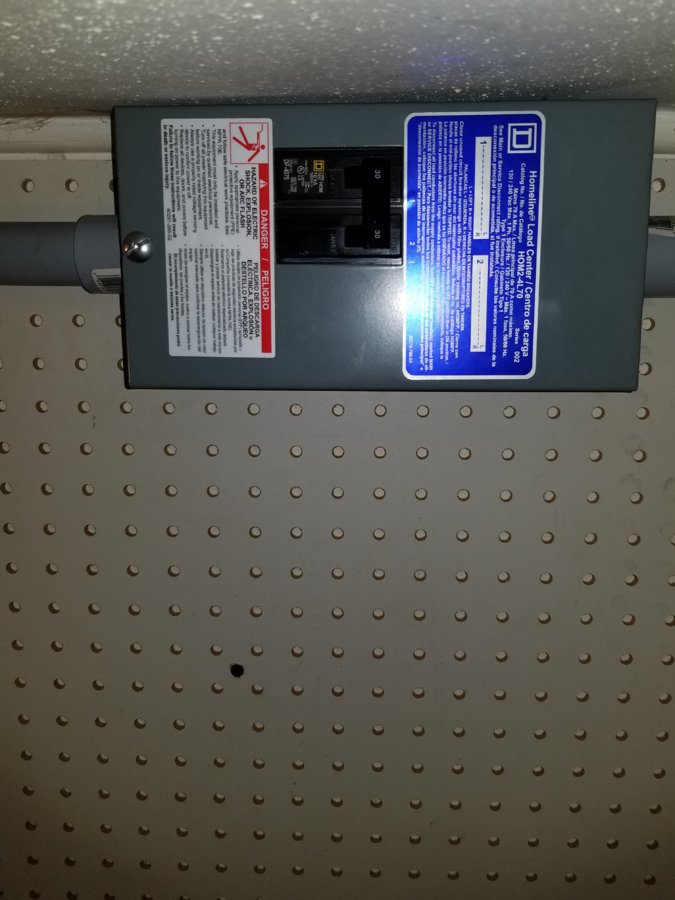
Goes outside runs for about 15 foot then comes back in to a breaker box
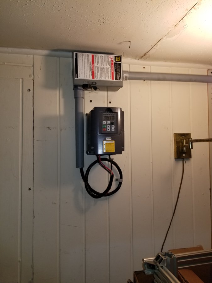
Where i have it for now directly hooked to the VFD later i plan on using some kind of plug.
Ok so a friend and i wend over the Spindle and VFD and it looks like even though the spindle plug is dented into the top of the spindle some it is fine nothing shorted out. so it looks like my problem is with my VFD.
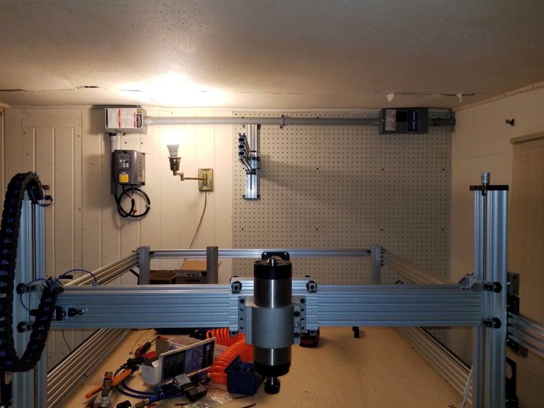
on a different note here is a inprogress idea on how i will run my air
Got the new VFD in and test mounted and its working yay
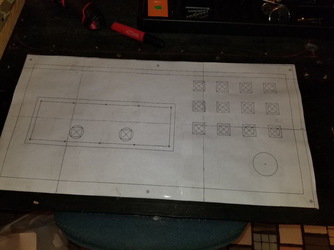
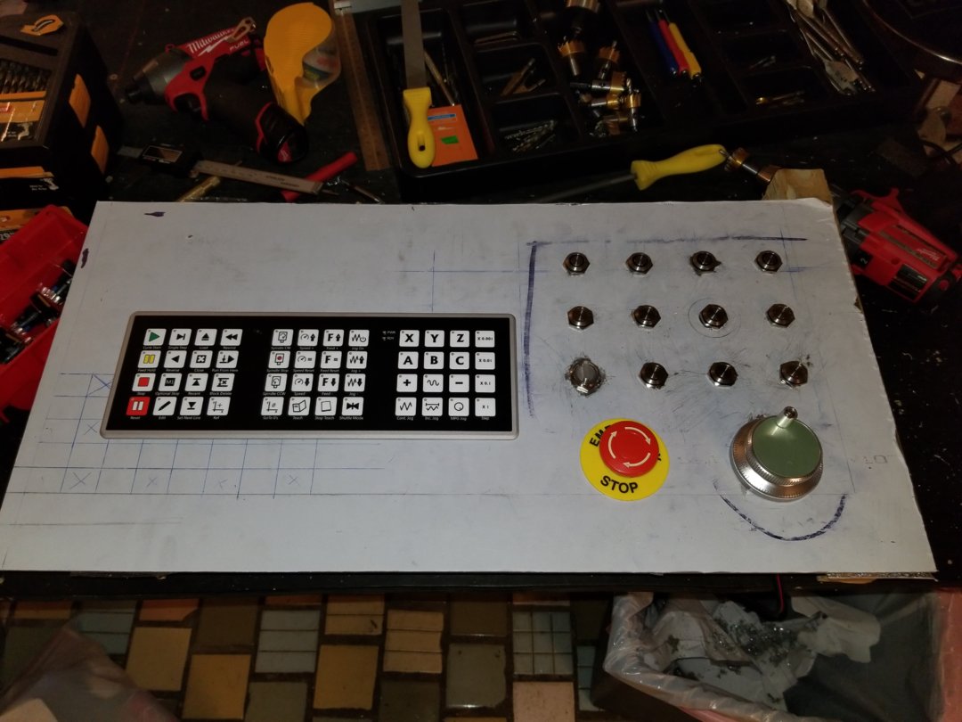
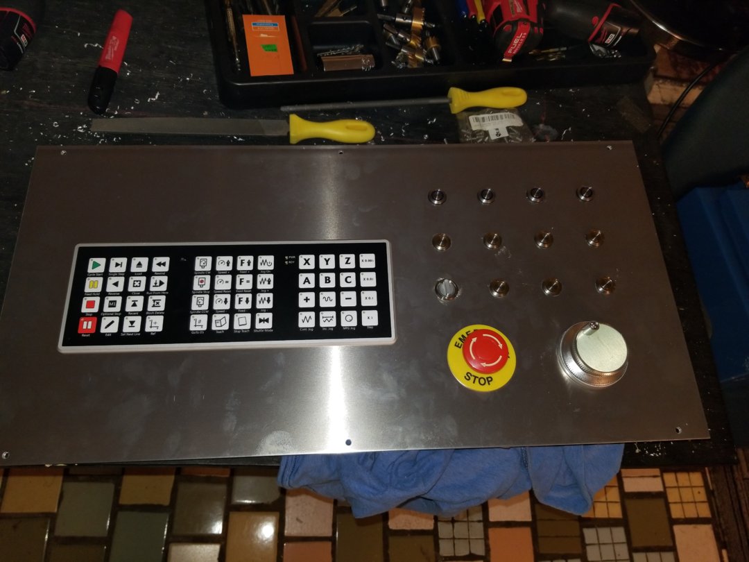
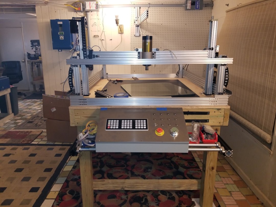
My control box is held in place with magnets i can slide it to either side of the table. All i got to do now is get all the holse drilled and wire everything up.
Thanks for checking out my build please feel free to ask any questions . vote for me.

Gooshpoo's H style cnc machine
Build in 'Other Style CNC Mills' published by Gooshpoo, Mar 21, 2018.
A cool project about my cnc machines unique style.
-
-
Build Author Gooshpoo, Find all builds by Gooshpoo
-
- Loading...
-
Build Details
- Build License:
-
- CC - Attribution - CC BY
Reason for this Build
To challenge myself, ive always wanted to -
Attached Files:
-
Attached Files: