
I’m slowly going from dream to practical on this project.
I do a lot of repairs and DIY projects around the house and just got sick of throwing things away or doing a mediocre job because I couldn’t get the right part. When I stumbled across OpenBuilds I started to dream about what it would take to be able to build my own parts and maybe even do something besides make sawdust on my wood working projects.
My original idea was to save space by combining a CNC mill and a 3D printer into one machine. I started by looking at Marshall Peck’s “Voxel OX - Extendable 3D Printer and CNC Platform”. As I read the discussions on several of the builds I realized I’d need a much stronger frame/system if I were to do the milling. The Ox derivatives and especially Ronald van Arkel’s “Upgrading the C-Beam machine” provided the details on how to do this. I just fell in love with the wheel sandwich.
I started by listing all the things I wanted to be able to do with this machine. The main ones were:
Mill aluminum – ½” max
3D printing
Woodworking – mill 24” wide cabinet doors
Able to be upgraded with a rotary axis – want the ability to shape table legs
There is a lot of discussion on OpenBuilds about flexing of the beams and adding wheels to minimize tilt so I’m going with C-beam actuators and wheel sandwiches.
This resulted in a monster about 1.5M x 1M x 1M in size.

You’re probably wondering what that “extra” beam is attached to the tool holder – it’s an attempt to stiffen the tool holder so it doesn’t rock front to back when milling. Where did that come from? I’m sure it came from an OpenBuilds project but I can’t find it anymore.
There were two big issues with this concept:
Lesson #1 – it gets really expensive when you order parts before the design is close to being finalized.
- I’d have to do some serious house cleaning just to build it and then I’d have a large area that was dedicated to a seldom used machine.
- I couldn’t find a Y/Z axis connection that seemed robust enough .
- I assumed that the 1.5M Y axis needed to have supports in the middle so a wheel sandwich was out. The six wheels on a X-Large gantry plate just didn’t seem strong enough.
- Having the small side of the Z axis actuator attached to the Y/Z plate seems like it’ll allow more flexing than if the wide side was attached. I can’t attach to the wide side because I can’t figure out how to make the Z/X axis connection if I do.
Lesson #2 – all the little parts can easily be more expensive than the main components
Lesson #3 – don’t order parts late at night. Too many mistakes and omissions!
Next concept was to go to 750mm actuators for all axes. This would give me a cutting area of about 15” x 17”. I assumed that at 750mm I wouldn’t need to support the Y axis in the middle so I could go to a wheel sandwich for the Y/Z connection. That still left me with the Z axis wide/narrow attachment conundrum.
By now I was getting a fair amount of parts in. I was really surprised by how heavy the router and the Z/X gantry was going to be. That made me re-think the fixed bed vs. moving bed decision. It looks like the Z/X gantry was going to be much heavier than my worst case work piece
Lesson #4 – it gets really expensive when you order parts before the design is close to being finalized.
That took me to looking at moving bed designs. I definitely didn’t like the ones where the table was only supported at one point. Here’s what I came up with:
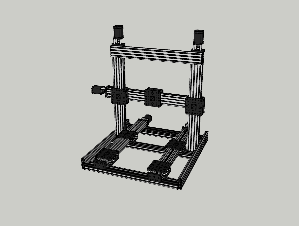
This really cut down on the X/Y cutting area if I stayed with 750mm actuators. Going to 1M actuators and keeping the overall width of the base to 29” (the width of my table) got me to a cutting area of 13.5” x 18”. The Y axis isn’t going to be supporting a lot of weight to I’m hoping that supporting it only on the ends will be OK. Supporting it only on the ends also allows me to go back to a wheel sandwich which allows me to mount the Y axis so the open section is down so that cuttings don’t fall into it. I’m using 20x20 v-slot to elevate the Y axis above the 20x80 v-slot of the frame which gives me more Y axis movement.
Off to order more wheel kits, X-Large gantry plates and v-slot beams.
Lesson #5 – it gets really expensive when you order parts before the design is close to being finalized.
Solved the Z axis wide/narrow attachment conundrum. Just use the cast corner brackets to attach the X axis to the Z axis sandwich plates. The black angle corner won’t do the job. The only additional components I’ll need are M5 – 15mm bolts to attach the brackets to the X-Large gantry plates.
Lesson #6 – sometimes it’s hard to see the obvious
I’ll be going with a fixed bed design that has a footprint of about 29” x 40” (at least for the next couple of days).

I’ll put the SketchUp files the moving bed and final fixed bed concepts into the docs section. The dimensions aren’t accurate in them. They’re just so I could visualize the design.
--------------------------------------------------------------
update 22 Jul
People that know about CNC mills much preferred the moving bed concept. I've taken their advice and gone back to the moving bed design.
I've received the last of the mechanical items needed for the build. So far I've cut all the beams to length, tapped all the holes and built the base. I've just started on the Z axis.
http://www.openbuilds.com/data/attachments/18/18042-fd245a33d1f50252e4d19228b20690dd.jpg

One significant lesson from the school of hard knocks came from trying to tap the ends of the V-slot and the shortened C-beams using the drill/tap combo available in the parts store.
Lesson # 7 DON'T USE DRILL/TAP ON LONG HOLES (see lesson 8 for an update)
The results are much better using the tried & true method of drilling the proper size hole and then manually tapping them. Not as sexy and a lot more work but much better results.
I did a total of 24 holes with the drill/tap combo. The results were 2 drill/taps broken off in holes, 7 holes that weren't usable (M5 bolts wouldn't take any torque) and two C-beams that had to be cut shorter (and tapped). Unfortunately I didn't have the choice of cutting the V-slots shorter as I'd already cut all my beams to length and it was the two longest ones that had issues. I ended up drilling them out and tapping them to M6x1.0.
Now I'm looking for some M6 bolts that won't stand out like a sore thumb. Wish me luck.
I went cheap on the corner brackets. Instead of using the $2.75 black corner brackets I used the $1.50 cast corner brackets. I used the angle-grinder-in-a-vise to grind off the nubs whenever they would push the body away from the extrusion. Yes, I could have gone even cheaper and used the $1.00 L brackets but they just didn't look like they'd be as stiff as the cast corner brackets.
--------------------------------------------------------------
update 24 Jul
All the actuators have been attached. The moving bed couldn't be completed because I ran out of T-nuts.


There was one nasty surprise. I'm going to have to move furniture in order to get my machine out the door. I may opt for disassembling it at the Z axis mount (only 8 cast corner brackets). The disassembly method also means I can store it in a much smaller area. If I go this route I'll need to add connectors in that area.
I found out my 1M 20x80 V-slot side rails actually measured 1005mm. That made my 1000mm C-beam Y actuators not sit flush on the frame (the lip on the end plates hit the end rail). Rather than disassemble 90% of the mechanicals and shorten the V-slot I decided to just add 6mm spacers between the 90 degree joining plates and the rear end rail. That pushed the end rail closer to the font and now the C-beam end brackets just make it past the end rails so the actuators now mount as intended. Not pretty but effective.
One pleasant surprise. Cutting fluid made the manual tapping go much easier. Absolutely no aluminum smear on the leading edge to destroy the threads on the way out. All these years wrestling with taps only to find out the experts were right. Who'd have guessed?
I just started looking at the limit switches. I didn't see any elegant solutions/methods. Most stuck out like a sore thumb. I got a headache looking at the printed mounts so I'm going to shelve it for a week or two.
The next step is to fire up the controller and play with the stepper motors. I'm sure that this'll take longer than the mechanical portion of the build. Once I get confidence that the controller is setup properly then I'll be forced to mount the stepper motors and get serious about the wiring.
--------------------------------------------------------------
update 24 Jul (2nd update)
I need to modify lesson 7.
Lesson # 8 DON'T USE DRILL/TAP ON LONG HOLES WITHOUT USING CUTTING FLUID
I did 32 holes today with the drill/tap combo while using cutting fluid. Not a single issue. I tested all the holes with a 10mm thread engagement with the only failures being the rounding of the hex part of the bolt head. I did 8 holes with only 5mm of thread engagement with the same results.
See the discussion section for details on how I did the tapping:
Sure wish I'd known about cutting fluid at the beginning of the build.
--------------------------------------------------------------
update 28 Jul
I'm looking for a new controller.
My Azteeg X3pro is great for printing but it's not compatible with GRBL. The software makes assumptions about the hardware that my controller doesn't follow.
Suggestions are welcome.
--------------------------------------------------------------
update 30 Jul
I've decided to stick with my Azteeg X3pro. There's people out there doing CNC milling using the Marlin firmware. Not a great CNC system but I'm new enough at this that it'll be quite some time before I start to realize the limitations.
I've gotten my Y axis to move!
It's slower than I expected (25mm/s) but as long as I stick with 2 flute 1/8" & 1/4" end mills I'll be OK.
And it's noisy. I'll play with the micro-stepping and feed rates to see if I can find a lower noise combo.
--------------------------------------------------------------
update 2 Aug
Made my first cut today!
I just did a shallow pocket in a piece of scrap wood. It showed that all the pieces work, that my X axis needs to be aligned and that I need to watch more of the SketchUcam tutorials.
I can do CNC milling with the Marlin printer firmware. I can't drop the SketchUcam g-code directly into Marlin. I need to do some manual editing before Marlin will execute it without complaining.
I definitely need to investigate stepper motor performance and feed rates more. If I push the feed rate too high the system starts chattering loudly and slows down noticeably yet there is plenty of available power (pushing against the table as hard as I can doesn't affect the speed).
--------------------------------------------------------------
update 20 Aug
Been doing a few cuts and building a gcode postprocessor.
I'm building a dust shoe for my machine. It's based mostly on Chris Laidlaw's magnetic dust shoe. My first attempt failed when I overheated the magnets when melting them into the pockets I machined.
http://www.ebay.com/itm/Magnetic-Dust-Collector-for-Chrisclub1-Router-Spindle-Mounting-Kits-/261660129234?ssPageName=STRK:MESE:IT
Most of my time has been spent on a gcode postprocesor to convert the SketchUcam output to something that the Marlin firmware can use. I think it's ready for others to use so I've uploaded it.
I’ve been doing a lot of playing with ideas for easily switching between the milling tool and the 3D printing tool. My current concept is:
I had to go to the captive screws because there was a little movement between the plates if I just used standard screws. With a little playing around you could get the standard screws to thread through both plates but then there was no tension between the two plates. That meant the play that allowed you to thread the screws through was still present.
- Uses an X-Large gantry plate to mount the tool to. This way I have matching holes in the tool plate and the X axis wheel plate sandwich.
- Attach locator studs to the X wheel plate sandwich. Use M5 x 20mm low profile screws and Tee nuts as the studs. The Tee nuts also provide a wide flat area for the tool plate to rest against
- Bevel the corresponding holes in the tool plate to aid in assembly.
- Use home made captive screws in the pre-tapped holes to join the plates together.
- Mount a box to the other side of the X sandwich and mount electrical connectors for each tool on it.
I’ll put the details in the Files & Drawings section.
I’m still wrestling with the auto bed leveling sensor on the 3D print tool. Seems like the capacitive and inductive sensors are at best inconsistent. Looks like I’ll be going with some type of mechanical system. My main problem with the mechanical systems is the Thingiverse designs leave a lot to the imagination.
It took a lot of work to determine that the servo designs need +5V, ground, a PWM position signal and the mechanical switch signal. Right now it’s not obvious how to connect it to my Azteeg X3pro controller. Looks like I’ll be using one of the expansion ports for this.
--------------------------------------------------------------
update 2 OCT
I've been doing a lot of firmware work this last month. The next release of the Marlin firmware will have support for the R method of specifying the arc in the G2 & G3 commands (in addition to the I J method). It will also have G38.2 & G38.3 commands for setting the origin of the work piece. You can get the pre-release version by downloading the RCBugFix branch.
I've also submitted code to implement the M3, M4 & M5 commands so that I can turn the spindle on/off and set the speed.
I've added the SuperPID speed controller to my router. Combined with the M3, M4 & M5 commands I can now control the router from the g-code file/program. This should lessen the number of times I break an end mill when forgetting to turn the spindle on before executing a program.
I've also implemented hall effect limit switches. I think I've come up with a cute way of hiding them within the slots of the rails. I'll put the directions & BOM into the docs section today.
I've been merrily shooting myself in the foot (translation: learning the hard way). Things like router bits don't like running into the screws that hold down the spoiler board & cheap end mills, slow speed and aluminum is a bad combination & need to tighten the chuck more.
Looks like it's time to start on the 3D printer part of the build. It'll be about a week before I get a new chuck in so don't have any excuses to put it off.
Hmmm ... better start looking at drag knife designs. The wife has been threatening to get a machine for cutting greeting cards.
========================================================
Planned upgrades
- Improved actuator end plates
- allow all four stepper motor corners to be bolted to the actuator
- extensions to Y axis to eliminate need for cast corner braces
- end plates from C-Beam CNC by Kyo look interesting
- Build pretty box for the controller & SuperPID
- Add electrical connectors, etc. to tame the rats nest
- Rotary axis (quite some time down the road)
========================================================
I'll add a detailed parts list once I've got the machine running.
Major components:
========================================================
- 40x80 C-beam for all actuators
- X-Large C-Beam Gantry Plates
- (full size) Xtreme Solid V Wheels
- Low current, high torque 23HS41-1804S Nema23 steppers
- Azteeg X3pro controller (mostly because it can run 8 stepper motors)
- 24V 30A power supply
- Bosch Colt router
- E3D V6 1.75mm hot end
- Extruder from the parts list in Marshall Peck’s “Voxel OX - Extendable 3D Printer and CNC Platform”
- Hot Bed PCB MK2A 300x300mm PCB 24V 360Watt
Tools I’ve used so far:
- Table saw with Harbor Freight metal cutting blade
- Drill press
- Metric hex (allen) wrenches - ball end type is easier to use
- 8 mm socket for the nylon stop nuts
- 8 mm wrench for the eccentric spacers
- Angle grinder and hand held drill to make the captive screws
- Metric drill bits
- M5x0.8 combo drill bit & tap (Open builds SKU 116 or Greenlee DDTAPM5C) (wish I'd known about the wonders of cutting fluid before I started using it)
- M6x1.0 tap and 13/64" drill
- large carpenters square
- 11/64" drill and an M5x0.8 manual tap
- cutting fluid
- strong magnet (for fishing nuts & bolts out of areas I couldn't get my fingers into).
--------------------------------------------------------------
update 26 NOV
Did my first calibration runs with the 3D printer head. Managed one nice run and two clogged nozzles.
Looks like I'm down until I figure out how properly startup and shut down a print run and how to unclog the nozzles. Off to the internet I go.
The spindle speed software hasn't made it into Marlin yet. They want me to add reasonable pin assignments to the pins_xxx.h files for the controllers that Marlin supports. There's 60 of them so it's a non-trivial amount of work. I'll need to get the schematics and board layouts to be sure the pins I pick are physically accessible. I'll also need to measure the PWM duty cycle and frequency on my controller so I'm sure of which ones are useable and which ones are dedicated to system interrupts.
Dream to practical
Build in 'Cartesian Style CNC' published by Bob K, Nov 26, 2016.
This is my journey from a dream machine to a practical (for me) machine. This is a Cartesian style frame that can change tool heads quickly. The first version will have milling and 3D printing tool heads. Later on I'll add a drag knife tool head.
-
-
Build Author Bob K, Find all builds by Bob K
-
- Loading...
-
Build Details
- Build License:
-
- CC - Attribution - CC BY
Reason for this Build
Because it's sexy & the wife says it'll keep me out of her hair.Inspired by
All the Ox derivatives, Marshall Peck’s “Voxel OX - Extendable 3D Printer and CNC Platform” and especially Ronald van Arkel’s “Upgrading the C-Beam machine” -
Attached Files:
-


