Hi Folks,
I wanted to throw up a quick note as I have received a few emails today about some misbehaving V3 boards. On the new V3's (gloss soldermask, not the matte V3s) the step enable line is inverted (setting $4, the command to set is "$4=1"). These are all pre-burned in with the our customized GRBL but there are some "known settings" out there for the various builds (using older boards) that are throwing some users off. So if you send a movement command and the driver don't do anything, flip the setting on $4. Let me know if anyone has any questions ([email protected])!
Thanks,
Mike
========================CNC xPRO V3 RELEASE===========================
The 3rd version of the xPRO is being released on Black Friday. We are very excited about the new edition and have rolled tons of user feedback into making this the best imaginable. There is an OpenBuilds blog posting on the new features but I wanted to re-hash and expand upon that here for completeness of this page (and add pictures). The V3 still has all the features of the older V2:
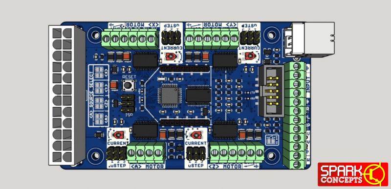
3D model of the xPRO V3 has been added to the OpenBuilds Sketchup 3D Warehouse.
- 4 DRV8825 powered stepper connections
- Full to 1/32 stepping
- Options for input and feedback include E-Stop/Reset, Feed Hold, Cycle Start, Homing Location (X,Y,Z Limits), and Z-Probing (now broken out to screw terminal)
- Spindle Direction and PWM Control output
- Current limiting adjustments for each axis
- Comes with heatsinks installed
- Optional ATX or 2-wire power input (12 or 24VDC)
New for V3:
What this all looks like...
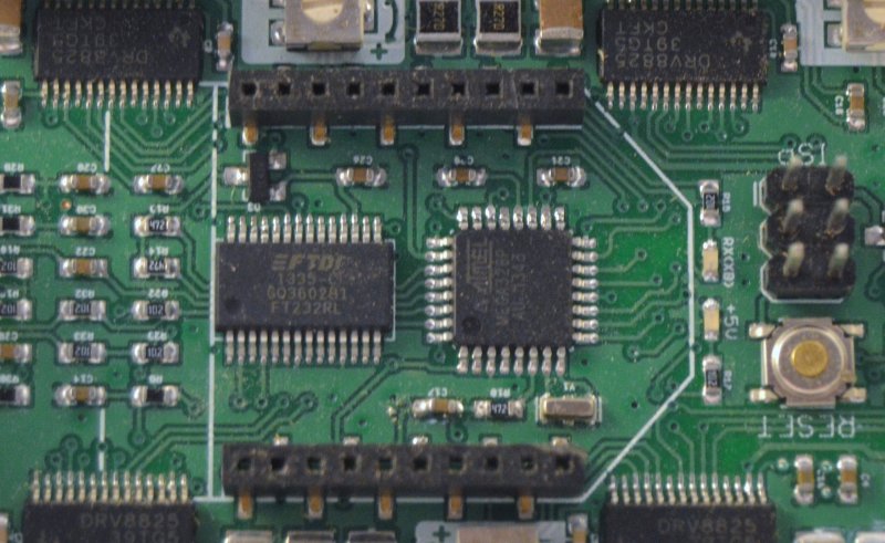
- New/Improved FTDI serial USB interface
- 100% Input buffering to include limit switches (prevent false triggers)
- Auxiliary PC fan header (12/24VDC depending on supply voltage)
- Motor driver output LEDs
- Step/Dir breakout pads to add external drivers
- Beefed up overvoltage/reverse voltage protection
- Redesigned silkscreen (more pictures, less words)
- Z-probe pin now accessible from screw terminal
- Default set to mixed decay (easily changed to slow or fast with jumpers)
- Same form factor as the V2 boards
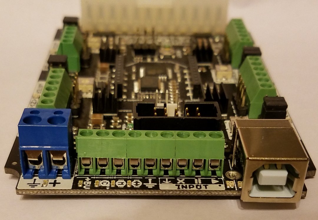
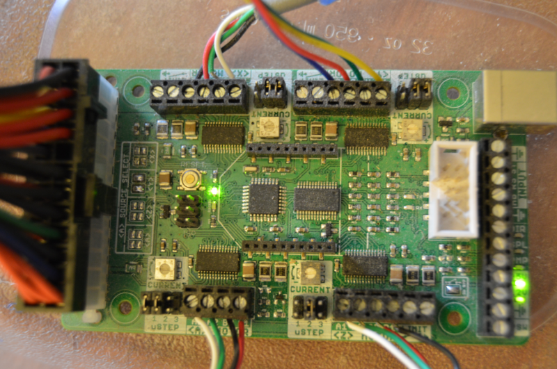
New board edge input/output (with pictures!). From Left to Right - Ground, Vin, 5V, Coolant enable, Spindle control PWM, Spindle Direction, Ground, Z-probe, Stop, Pause, Resume.
Motor power LEDs - these will light when moving (directly tied to motor driver output)
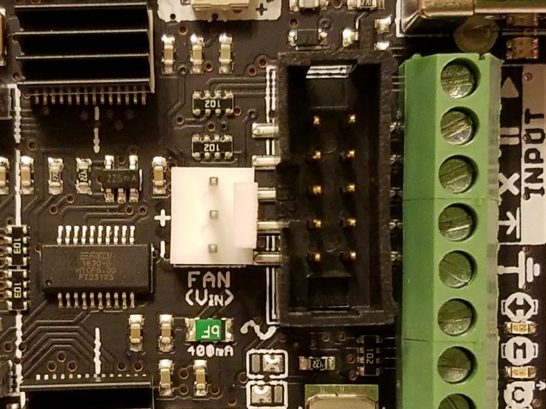
New Aux fan plug - please note this is tied directly to input voltage Vin (so if you have a 24V supply use a 24V fan)
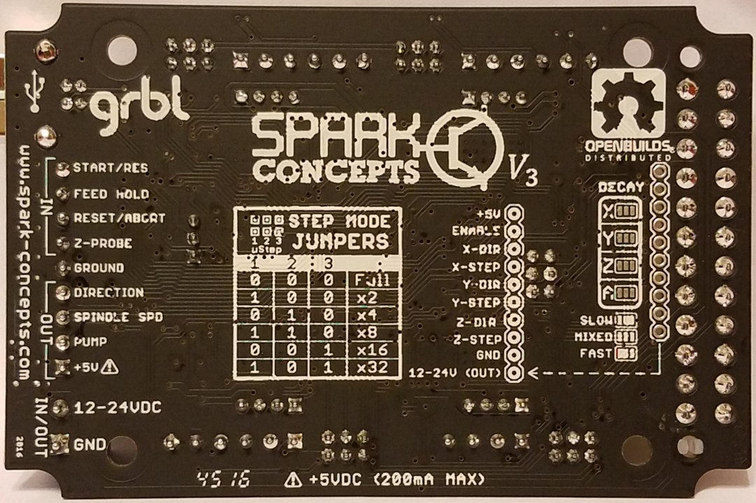
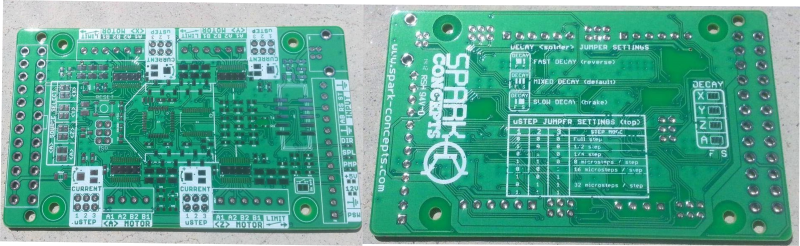
Lastly, the back - mostly because it's pretty... I mean it has jumper settings guide, decay jumpers, verbage for board edge connector and step/dir output pads and label... but mostly its pretty
Please feel free to ask questions if there is something that you would like to know
======================Older Posts================================
A few housekeeping things:
1) Please do not use GRBL Controller with the xPRO - we have 2 customers report issues with the xPROs being bricked - we are looking into this currently. As always our suggested program is Universal Gcode sender.
2) the xPRO's V2 are shipping with GRBL 0.9g - this means the baud rate is now 115200 not 9600
3) for some reason a few people have had issues with the drivers installing automatically on plug in. If this happens you can download the drivers from FTDI's website here -> http://www.ftdichip.com/Drivers/VCP.htm
Now onto the fun stuff
Up first - Variable Speed Spindle (VSS) Control
This has been a long time coming and took some time dealing with a lack of documentation on the governors...
Things you will need:
xPRO controller
48V power supply
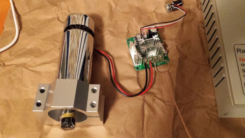
400W Spindle Kit with Speed Controller
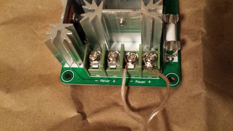
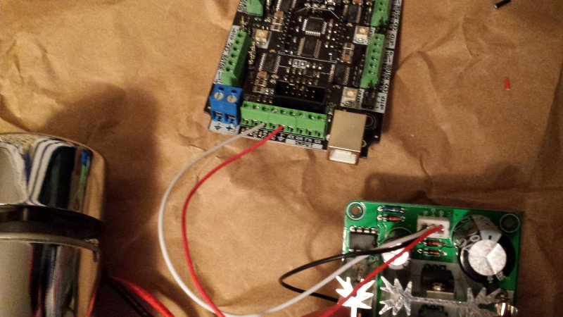
In short, you will need to wire your 48V power supply to the "power" port of the governor. (the wire used was for demonstration only - when actually in use the spindle will draw lots of amps - please do not use speaker wire for this part...)
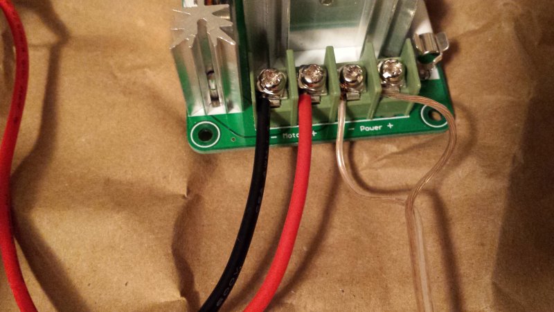
Wire the spindle to the "Motor" port of the governor.
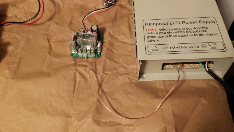
Last, wire the SPL and GND pins of the xPRO to the "PWM" port of the governor. (This plug uses red for GND )

Now to the software - with GRBL 0.9g there are compile time option to turn on VSS which will swap the zlim and the spl pins. The V2 xPROs are defaulted to run VSS with the default setting of MIN_RPM=0 and MAX_RPM=1000. These values should be changed according to you spindle specs. However, you can always correlate the 0-1000 scale to your spindle such that a command of VSS 700 would in fact be 70% of your actual max speed.
To do this simply send command:
M3 S700 <- here the 700 would be the spindle speed you want)
From a quick survey it appears that most of the xPRO's are being used with the OX-es (OXen ?) - we would like to release an updated hex with default OX settings / VSS settings so anyone wanting to run an OX with VSS can do so without changing anything. This is where we need some help - if you are willing to help out please send us the settings you are using in your OX builds (send command $$ then send us the response). Thanks!
======================OLDER POST============================================
We have been working on a CNC router for the shop for a little while now. On finishing the hardware design (Routy's fatter sister) we started looking into electronics and found very little that fit our budget and desired capabilities (I personally have never been a huge fan of shield stacks for final products, or wiring two motor to one driver). We wanted a single board capable of driving 4-motor machines (whether that setup is a 3 axis with dual motor on one axis or a true four axis machine). We also wanted to be able to drive Nema 17, 23, and 34's from this board. That is where this project begins...
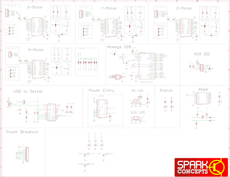
Taking a look under the hood:
Here is a look at the schematic for this board (.PDF is available for download in the files section – additionally the.SCH file is coming soon on the Spark Concepts website). NEW SCHEMATIC INCLUDING FORUM SUGGESTIONS!
- 100% GRBL compatible
- Product dimensions: 2.35”W x 4.15”L x .65”H
- Capable of powering from ATX PSU (these are dirt cheap and I have tons laying around from recycled desktops)
- Drive 4 motors with DRV8825 Stepper Drivers - 2.5A (peak) with 1.75A (RMS) with up to 1/32 microstepping
- 1 Driver capable of cloning X,Y, or Z or being run independent
- Hardware support for both USB and Wireless (Xbee) Operation
- Emergency Stop to cut all motor power (with optional override
- 12V and 5V outputs for powering peripherals (fans, pumps, vacuums)
- Easily connect to Stepper Motors and limit switches with 3.5mm screw terminals
- Expansion port for future upgrades (handheld jog controller, integrated spindle speed control, etc)
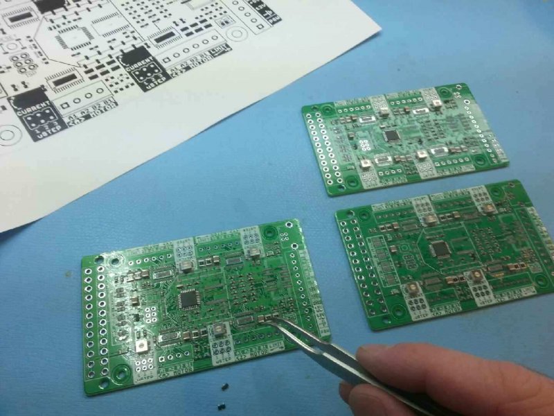
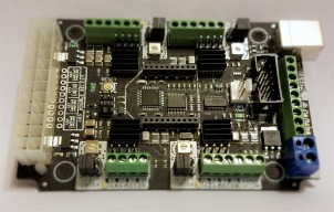
And the boards back from the fab house
And the hand assembly process for the Beta boards (coming soon: Surface Mount assembly tutorials)
Voila, the Final assembled board
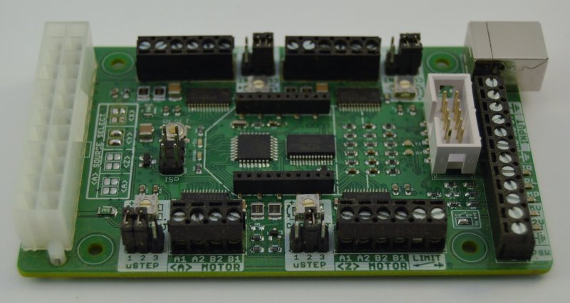
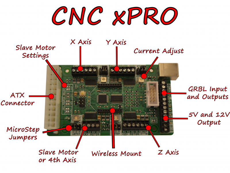
A few quick pictures of what's what...
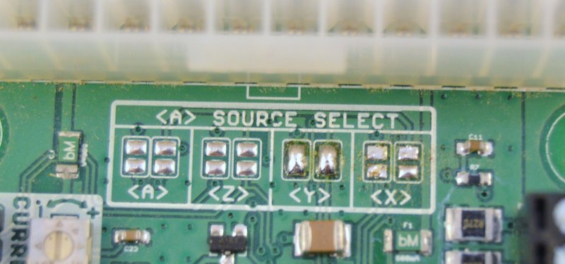
Source setting for motor A
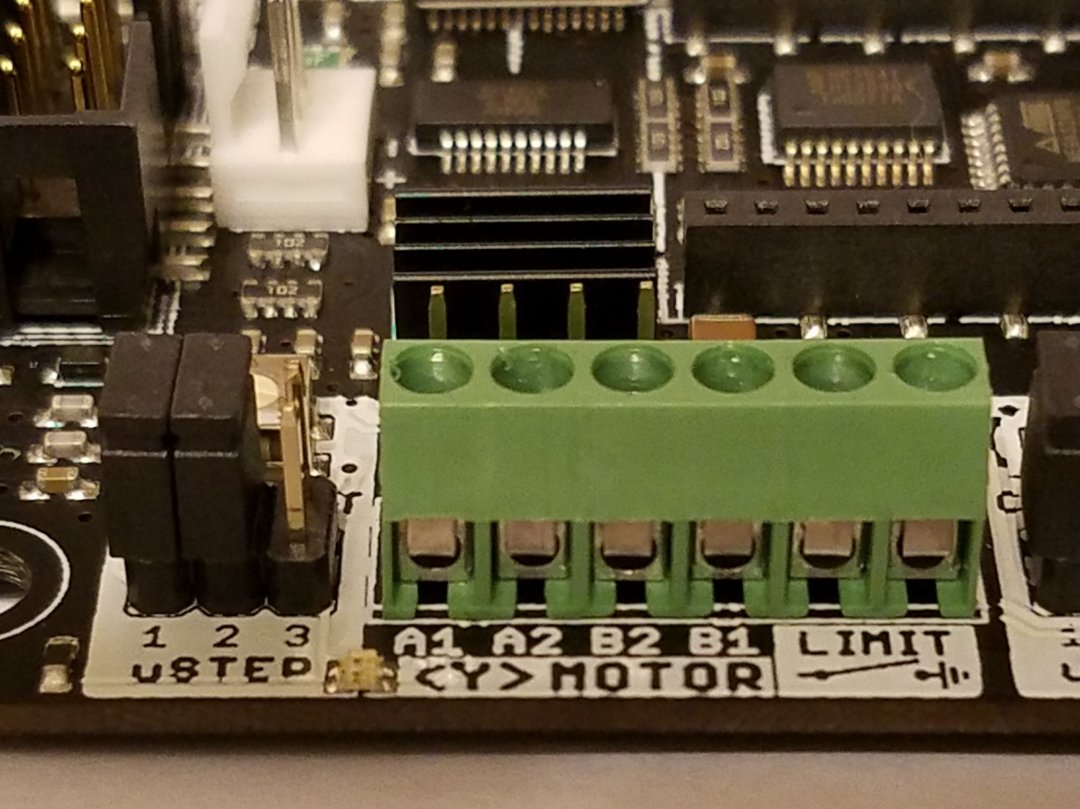
Microstep jumpers, Screw terminal for motors and limit switch, current limiting pot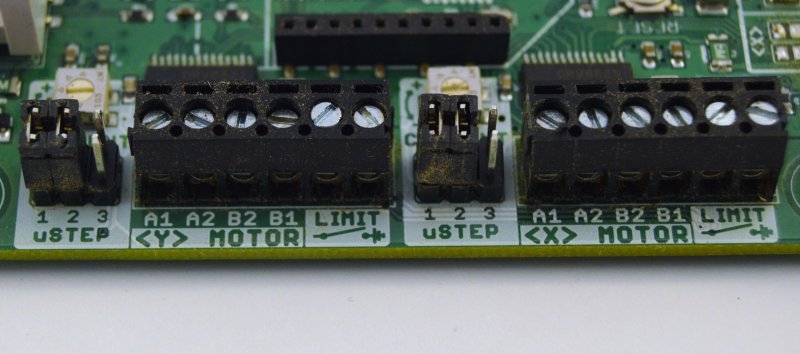
Xbee headers (can also use Bluetooth, Wifi, etc)
Emergency stop, 12V and 5V output, pump spindle and spindle direction output. Inputs for abort, reset, stop. Expansion port (white 2x5 header)

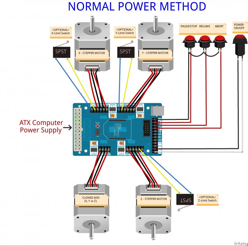
WIRING UP WITH AN ATX SUPPLY
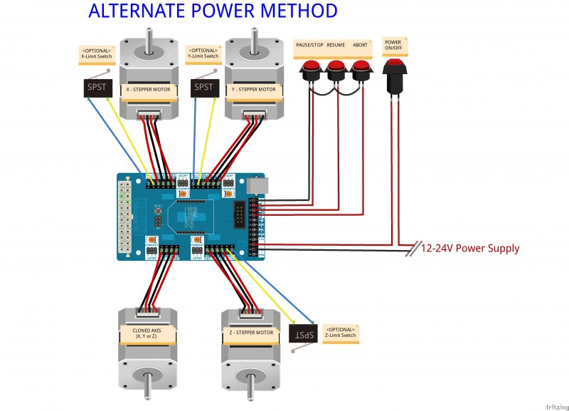
WIRING UP WITH A 12V/24V SUPPLY
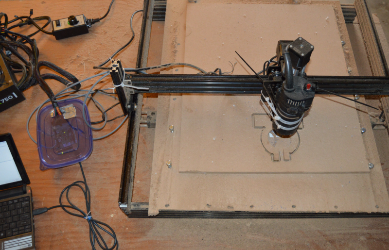
Testing !
Wired up and fired up
Slap it in some Gladware and its ready to go...(don't forget the Duct tape seal
First test piece was a new mount for Routy to replace the zip ties (quick tip - to many zip ties will bend the build plate
That's all for now... more videos coming soon.
CNC xPRO Driver
Build in 'Circuit - Software Project' published by Spark Concepts, Oct 9, 2017.
Spark Concepts CNC xPRO Driver. A new GRBL compatible, all-in-one stepper driver board with 4 motor controllers for XYZ + 1 clone (or rotary!). Capable of powering your next build with an ATX PSU (or 12V 2 wire supply), and ready for wireless printing. Compatible with Arduino (wireless robots anyone?)
-
-
Build Author Spark Concepts, Find all builds by Spark Concepts
-
- Loading...
-
Build Details
- Build License:
-
- CC - Attribution NonCommercial - Share Alike - CC BY NC SA
Reason for this Build
We wanted an extensible controller that provided independent drivers for 4 motor CNC designs. From there started adding features for powering from ATX and wireless printing.Inspired by
-


