
Details and Specifications
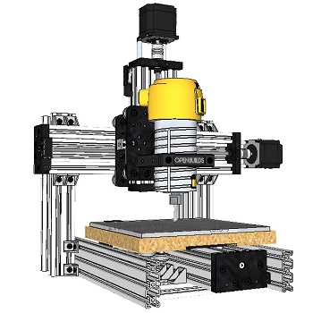
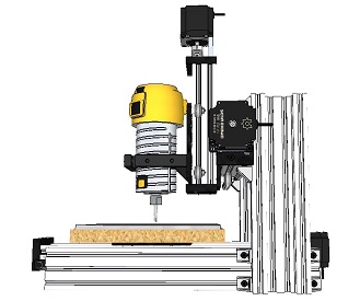
Build name: C-Beam Mini Mite
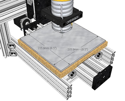
Usable Build Volume: 8.5" x 8.5" x 2.25" (216mm x 216mm x 57mm) based on using 3/4" build plate
Build Plate/Spoil Board Dimensions: 9" x 9" x 3/4" (228.4mm x 228.4mm x 19.05mm)
Overall System Dimensions: 18.75" x 18.75" x 18.125" (476mm x 476mm x 460mm)
Base Dimensions: 12.6" x 18.75" (320mm x 476mm)
Weight (including build plate): 26.4 pounds (12 kg)
System Cost: Base system cost is roughly $12 more than the base cost of an OpenBuilds Mini Mill and most of this is due to hardware overages (due to the 10 pack hardware units). But that's where the close proximity ends. As the system doesn't come as a package deal and the electronics in the package deals offer substantial savings the total cost comes to roughly $87 more than a Mini Mill. But for that $87 you get roughly 3 times the build volume. (Note: price differentials provided are based on current prices at the time of publication.)
Drawings
Extrusion and Lead Screw Cuts
The magic of the system and being able to keep costs to a minimum came from optimizing part lengths and then cutting them from longer, more economical pieces. Below is a diagram of the part cuts and how they fit into the larger pieces from which they came.
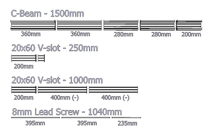
The good people of the OpenBuilds Parts Store were kind enough to cut the parts for me and did an excellent job doing so. I put the following note in the comments section on the order and everything came as specified:
"Please cut the 1500mm C-Beam as follows: 2@ 360mm, 2@ 280mm, and 1@ 200mm. Please cut the 20x60x250mm @ 200mm. Please cut the 20x60x1000mm: 1@ 200mm and split the remainder in 2 equal halves (400mm +/-). Please cut the lead screw: 2@ 395mm and 1@ 235mm. Thank you. Hopefully this build turns into the next big thing at OpenBuilds!"
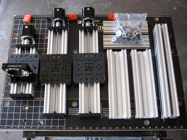
Assembling The Build
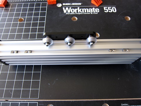
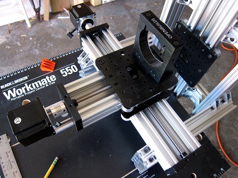
The build is broken down as 3 actuators, 6 framing members, and 32 cast corner brackets, The actuators as shown are 200mm, 360mm, and 360mm. I won't go into assembling the actuators as the process is already well documented. The X and Y axes use 6 wheel gantries while the Z-axis uses 4.
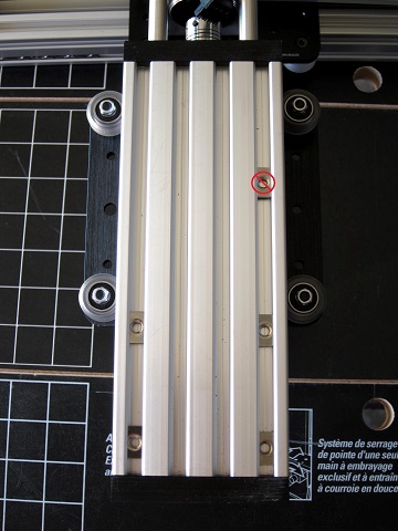
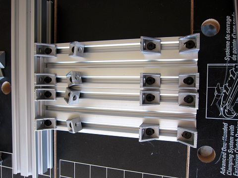
The X-axis requires 4 T-nuts be installed both the top and bottom edges and 4 more in the back side during assembly as shown. (Note, the 4 in the back side are for the BlackBox and if you desire to mount it elsewhere please disregard them.) The Y-axis requires 4 T-nuts installed in both the top and bottom edges as shown. (Disregard the marked out T-nuts. These were for wiring attachments that didn't pan out.)
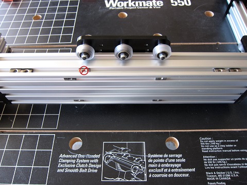
And finally, the Z-axis requires 4 T-nuts installed in the back side.
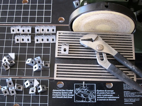
Tabs on one face of the 32 cast corner brackets will need filed or sanded off. I used a bench disk sander which made quick work of them. Note, there is a 33rd cast corner bracket in the bill of materials. This last bracket will need tabs on both faces removed so might as well do it now while you're set up for it.
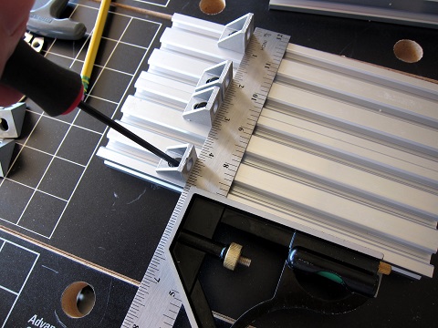
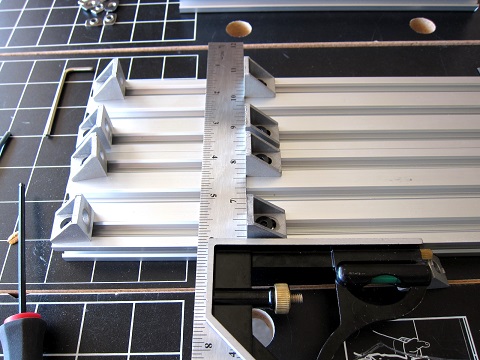
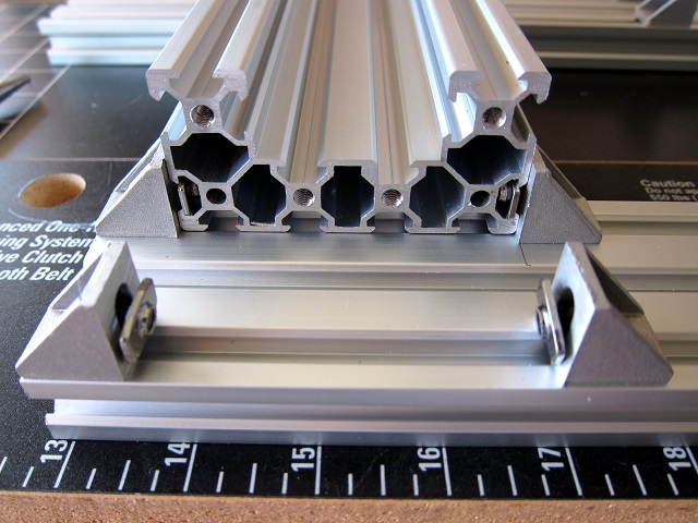
On the 20x60x200mm base framing members set 2 corner brackets on each member 60mm from the end. Use a square to get them properly inline and square as the Y-axis will be drawn up to them as it is attached. Attach the remaining corner brackets as shown in the right photo using blocking to get the end brackets square and leave the other set of center brackets floating as these will be drawn up to the Y-axis after the axis has already been drawn up against the squared set. (Note, blue tape was used on the bottom side of the extrusions to hold them together in alignment.)
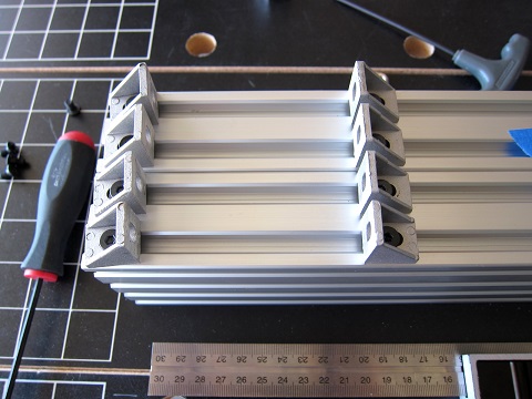
Perform a similar attachment on the 20x60x400mm side rails setting a row of corner brackets square at a distance of 100mm from the end. Leave the brackets at the end loose as these will be drawn into place later. Similar procedure for the vertical C-Beam framing members as shown in the second photo below. Set the squared brackets 105mm from the end and leave the corner brackets at the end loose. Note vertical members should be created as a mirror image set.
Attach the base framing members to the Y-axis as shown, connecting to the squared corner brackets first and draw the loose ones in to secure. The base frame at the front should be roughly 70mm from the front edge of the actuator extrusion and the one at the rear should be set approximately 10mm forward of the rear edge of the extrusion. While it is shown flush in the picture it became apparent later that moving it forward allowed for a better path for the Y-axis end stop wiring.
Slide the vertical C-Beam framing members into the 20x60x400mm side pieces until the bottom edges align and secure, tightening the squared brackets first and then drawing in and tightening the floating end brackets. Brackets on the far ends of the C-Beam members should be pointing toward the long end of the 20x60. Photo shown is for the left side support.
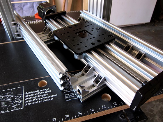
Slide the side framing members into the base framing clips as shown. Exact location lengthwise isn't really important as they will be adjusted to proper position shortly. Getting them equal side to side is all that is important. Snug up the connections but don't worry about getting them tight as they will need to be loosened a few steps down. The second photo below shows what you should have at this point.
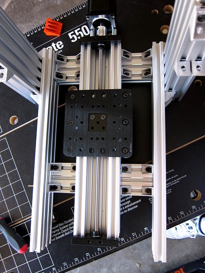
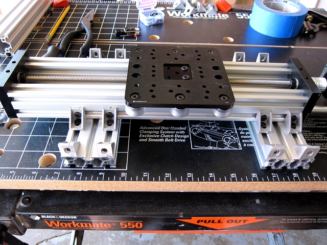
The following section is where I realized I did things a bit out of order. As the photos show I mounted the X-axis and then attached the Z-axis to it. This turned out to be extremely difficult getting the Z-axis mounting screws to match up with the embedded T-nuts. I strongly recommend attaching the Z-axis to the X-axis first and then mounting the X-axis. The Z-axis is fastened to the X-axis gantry plate with (4) 12mm screws through the back side of the gantry plate into the T-nuts previously inserted in the back of the Z-axis. Then mount the X-axis assembly to the vertical C-Beam framing in a similar manner to the other connections up to this point. Be sure the X-axis is drawn tight and square up against the vertical C-Beam framing. Note for better centering of the tool head over the work area (due to the end stop eating some distance at the left end) the X-axis should be set about 3mm left of center.
Centering the Bed/Work Area Under the Tool Head
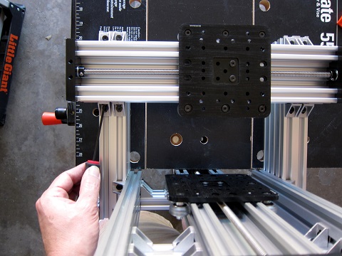
Adjust the Y axis gantry plate to the measured center of the axis and then move it about 3mm toward the rear. Adjust the X-axis gantry plate to the center of the axis and then move it about 3mm to the right. Drop in the router with a 1/4" bit and lower it down to the Y-axis gantry plate. Loosen the side rails and slide the combined side rail/upper gantry assembly to where the router bit is centered over the center hole in the Y-axis gantry plate. Tighten the side rails to secure. Adjust the X-axis if necessary.
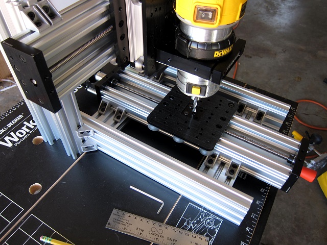
And this is where you should be at this point
Creating the Build Plate/Spoil Board
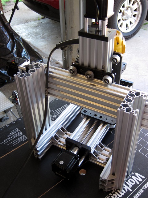
The main problem with the C-Beam end plates jutting up as far as they do is they restrict motion of the build plate. This is easily resolved through either adding a 4mm shim plate to raise the board or cutting 4mm recesses in the bottom of the board. As a shim plate would require adding a non off the shelf part to the build I went with the recesses in the board. The recesses are 84mm wide by 52mm deep along the axis. I used the Adjustable Router Guide I built a few years ago out of 20x60 extrusion but there are any of a number of ways of approaching this. While this step may seem a fair amount of effort in reality it really wasn't much of an issue. The 4mm recess adds about 3 1/2" to the range of the Y-axis which more than makes it worth the effort.
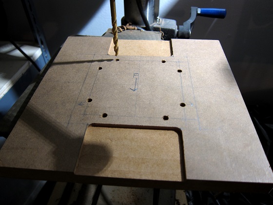
Measured and drilled through holes through the board. Flipped and counterbored the holes to recess the screw heads. Board is secured with M5x20mm screws into the threaded holes in the gantry plate and M5x27mm screws with nuts on the bottom at the smooth holes in the gantry plate. This is another area where I wish I had had a bit of foresight. It would have been much easier to locate the holes using the gantry plate as a template before mounting it in the actuator assembly. Additionally, if the build plate is created prior to the beginning of the system assembly the 20x60 framing members could be used as a router template.

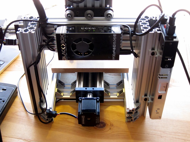
Electronics and Wiring
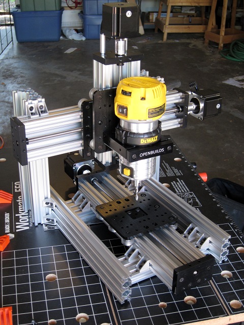
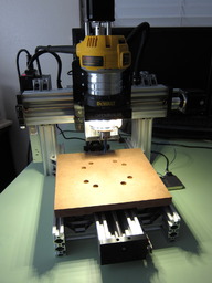
Electronics were mounted as shown on the system. If I were to do it again, I would probably mount the BlackBox on the vertical C-Beam opposite the power supply. It's a bit cramped where it is and this spot would be a better location for an Interface controller. Wiring overall was fairly simple because the runs were so short.
Conclusion
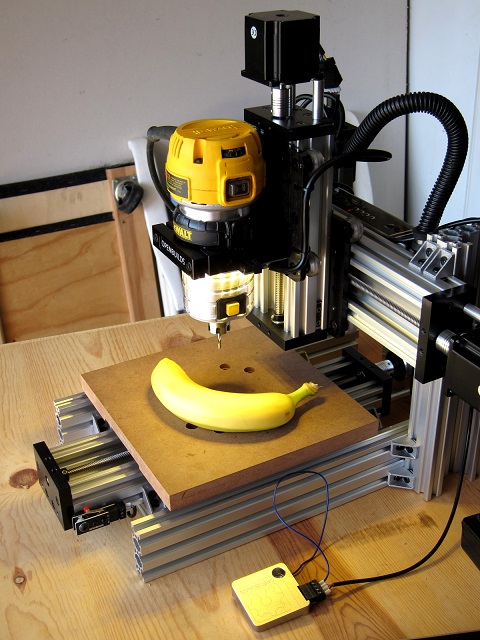
Overall I am very happy with the build, how compact it is and how stout it turned out, and just how easily it went together. In the long run I intend to replace the original Y-axis gantry plate with a 3/8" piece of cast tool plate and add some outrigger wheels on the underside of the build plate attached to the side rails in line with the tool head sweep to prevent any possibility of deflection at the corners of the plate. I will also be adding dust collection.
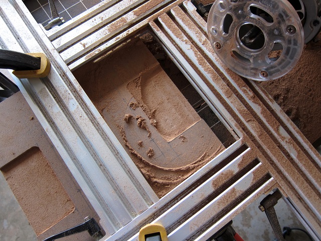
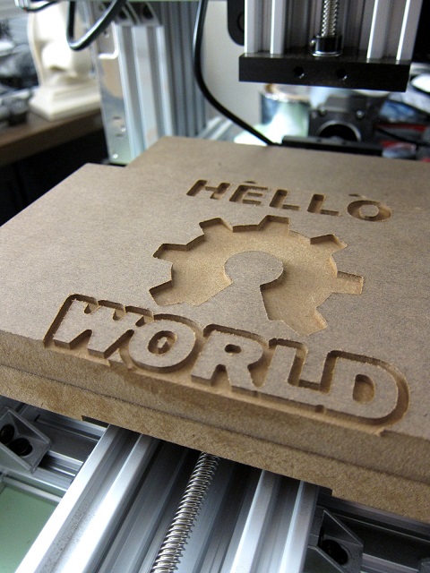
And finally, the customary banana scale and first cut "hello world" photos.
Sketchup file and Bill of Materials included in the Files and Drawings and Parts List tabs.
C-Beam Mini Mite
Build in 'X/Y Table Style CNC Mill' published by Rick 2.0, Jul 9, 2022.
A small system with a big bite. Design achieves a good balance between machine size vs. build area, rigidity and ease of construction all while keeping build cost as low as possible.
-
-
Build Author Rick 2.0, Find all builds by Rick 2.0
-
- Loading...
-
Build Details
- Build License:
-
- CC - Attribution NonCommercial - CC BY NC
-
Attached Files:
-
Attached Files: