
Click here for Fusion 360 Interactive Model
Summary
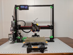
This printer is a design that has evolved over three years. The original goals of this project were to design a rigid printer that had a large print volume, 300mm^3, with easily sources parts and a minimum of complicated printed parts.
Nearly all of the parts were designed by myself in Fusion 360. There are a few accessories, such as the cable chain, that were sourced from Thingiverse. These parts will be included as links to the source as opposed to including them in the download.
I also wanted a machine with onboard controls. This one has two! The Azteeg X5 GT has a Viki2 LCD controller for direct firmware control, and the onboard OctoPI has a 3.5” TouchUI panel for more options.
Detailed Assembly Instructions
Frame

Materials
Assembly
- 2x 40x20x500mm V-Slot (Sides)
- 1x 20x20x640mm V-Slot (Top)
- 1x 80x20x640mm V-Slot (Bottom)
- 4x Large Corner Brackets (Printed)
- 2x 80mm End to 40mm side plates
- 4x Y-Axis Bracket (Printed)
- 8x M5x15mm Low Profile Screws
- 30x V-Slot Nuts
- 30x M5x7mm Low Profile Screws
Note: loose assemble V-Slot screws and nuts in all plates and brackets first. This allows you to slide them into place, then tighten the screws. Do not fully tighten until all parts are in place. This will allow you to square up the frame.
- Cut the VSlot rails to the specified lengths.
- Drill and tap M5 holes of both ends of the 80x20.
- Use the corner brackets to secure the 40x20 uprights to the 80x20 base using V-Slot nuts and M5x7mm screws.
- Attach the end plates to the ends of the 80x20 and the 40x20 uprights using M5x15mm screws in the 80x20 and V-Slot nuts and M5x7mm screws in the 40x20.
- Attach the upper 20x20 with corner brackets using V-Slot nuts and M5x7mm screws.
- Use a square to ensure ALL angles are exactly 90. Any slop here will case major degradation of prints.
- Finally, tighten all screws and double, triple and quadruple check the squareness.

Y Axis
Materials
- 2x Y End (Printed)
- Y Motor Mount (Printed)
- Y Idler (Printed)
- 4x Y Spacer (Printed)
- 2x 40x20x750mm V-Slot
- 8x M5x15mm Screws
- 1/4-20 x 1.5" Bolt
- 1/4-20 Nut
- 608ZZ Bearing
- 1/4-20 Fender washer x 2 (hold belt)
- NEMA17 Motor
- GT2 Gear
- GT2 Belt 1500mm
- 8x M3x10mm hex cap screw (motor)
- 10x M3x20mm hex cap
- 18x M3 washer
Assembly
- 10x M3 plastic inset
- Cut (optional) the 40x20x750mm V-Slot rails to length
- Drill and tap the holes of both rails.
- Using a soldering iron, melt the M3 inset nuts into the Y motor and Y idler (printed) brackets where they will meet the Y End.
- Attach the Y motor and idler brackets to the Y ends using M3 screws and washers.
- Attach the Y End (printed) to each end of the rails as shown in the photo. Use the M5x15mm screws.

- Use the 1/4-20 bolt, 608ZZ and fender washers to make an idler pulley on the idler mount.

- Use M3 screws to attach the NEMA17 motor to the other end.
- Attach the pully to the motor, check for alignment. It may need to be flipped as shown in the photo.

- Optionally, use Y spacers along the rails.
- Attach the Y endstop assembly to the idler end of the rail as shown.

- The belt will be run once the Y-Bed carriage is attached.
Y Bed
uploading
X Gantry
uploading

X Carriage
uploading
Extruders
uploading
Electronics
Materials
Assembly
- 1/8" x 9" x 12" Aluminum Sheet
- Motherboard Standoffs and Screws
- Electronics (Raspberry PI, Smoothieboard or RAMPS, Relay Board or MOSFET bed driver)
- For the electronics mount, use a 1/8" aluminum sheet.
- Lay out the PCBs in approximate locations and use a sharpie marker to mark the hole positions.
- Punch, Drill and tap the holes to match the threads of your motherboard standoffs. Mine were #6.
- Install standoffs and mount PCBs with screws. Some may need a plastic washer under the screw to prevent screw contacting traces or components. Uses the smallest head screw available.


Z Motors and Gantry Mount
uploading

Cleanup
uploading
BinaryConstruct V3
Build in 'X/Y Table Style Bots' published by BinaryConstruct, Mar 2, 2018.
This printer is a design that has evolved over three years. The original goals of this project were to design a rigid printer that had a large print volume, 300mm^3, with easily sources parts and a minimum of complicated printed parts.
-
-
Build Author BinaryConstruct, Find all builds by BinaryConstruct
-
- Loading...
-
Build Details
- Build License:
-
- GNU (GPL3+) General Public Licence
Reason for this Build
This printer is a design that has evolved over three years. The original goals of this project were to design a rigid printer that had a large print volume, 300mm^3, with easily sources parts and a minimum of complicated printed parts.
Nearly all of the parts were designed by myself in Fusion 360. There are a few accessories, such as the cable chain, that were sourced from Thingiverse. These parts will be included as links to the source as opposed to including them in the download.
I also wanted a machine with onboard controls. This one has two! The Azteeg X5 GT has a Viki2 LCD controller for direct firmware control, and the onboard OctoPI has a 3.5” TouchUI panel for more options.Inspired by
OpenBuilds Community! -
-
Attached Files:
-


