Not your everyday Open Builds project!
This is a build that I did for work. The actual product we are developing is confidential and hence is excluded from these pictures, but the application area might be obvious from some of the other things you can see here. We work on various projects that use computer vision algorithms. It's nice to have a way to test those algorithms using known scenes. In this case, our algorithm needs to identify ball speed, launch angle, azimuth, spin axis and spin rotation. While the machine cannot simulate these aspects in real time, we can use it to precisely position the ball for a stop motion animation effect.
I am glad Open Builds has started offering their V-rails and C-Beam actuators in black anodized form. This is useful for optical applications where the machine needs to "hide" in the background. Our end product uses infrared cameras. After attaching a black guard to the stepper motor behind the ball mount, the machine becomes almost completely invisible in the final images.
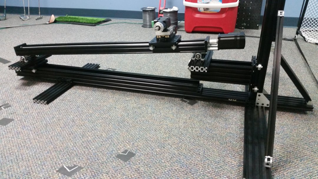
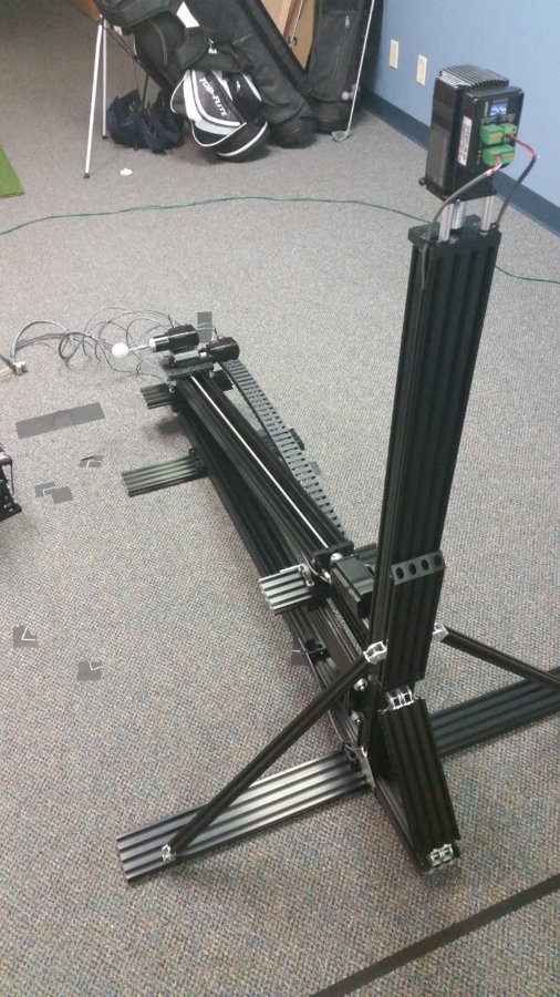
This machine uses three 1000 mm black anodized C-Beam rails. Two of the rails are used as linear actuators while the third rail on the bottom of the machine just acts as a guide without any lead screw or motor. The linear actuator perpendicular to the ground raises the one end of the "main" actuator to adjust the launch angle. As it rises, the other end will naturally move inward to balance out the 180 degrees of the triangular relationship formed by the actuators. The angles of the main actuator move freely thanks to ball bearing pillow blocks connected by 8 mm rods.
The motors used on the linear actuators are the NEMA 23-like JMC iHSS57-36-20 closed loop stepper motors with built-in drivers. The motors used on the gantry are the smaller NEMA 17-like JMC iHSS42-24-05 closed loop stepper motors. The gantry is a typical Open Builds XL gantry plate. Sitting on top of that is a PDV +/- 15 degree goniometer to adjust the spin axis angle. On top of that is a JMC motor connected to a 100:1 planetary gearbox through a NEMA 17 motor bracket which gives fine-grained control of the ball's backspin angle. Not shown in these pictures is an additional axis to control azimuth. This consists of a Sherline rotary table attached to the left support leg and a cantilever arm holding the customer product which takes the pictures for the vision algorithm.
All of these axes are controlled by a Novusun 5-axis NVH02+NCD02 standalone, handheld CNC controller, though I have been looking at using an Arduino DUE with g2core to automate the process. Currently, I've just been setting the step amount and then pressing the axis step buttons to move the gantry to the next desired position, triggering an image capture on the customer device, and repeating the process until a full shot's worth of images are obtained.
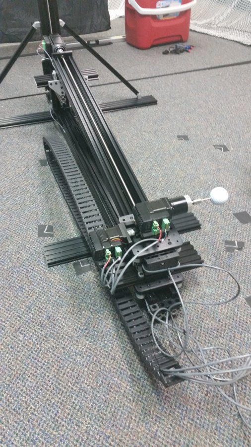
The ball is mounted on an 1/8" Dremel corkscrew mandrel. To mount it, I take a 2x4 piece of lumber and drill a hole into it with a Forstner bit on a drill press. Without moving the 2x4, I replace the Forstner bit with a small drill bit, insert the ball in the Forstner hole, then drill a pilot hole into the ball. Finally, I replace that bit with the mandrel and slowly lower the drill press and rotate the mandrel corkscrew into the pilot hole. The mandrel is then attached to the planetary gearbox shaft using an Actobotics 1/8" to 8mm rigid coupling. Both the coupling and mandrel are wrapped in black heat-shrink tubing to avoid infrared glare from the product's IR emitters.
The majority of the wiring is accomplished by shielded security cable from Home Depot. The motor power is supplied by 2-wire cable that is separate from the 4-wire cable used for the step/direction signals. The power cables are joined together with WAGO lever-nuts before connecting to a 24V Mean Well power supply that also supplies the CNC controller. A drag chain was attached to the goniometer motor with zip ties to make sure the wires leading to the gantry did not get caught in any undesired locations. The other cables running to distant locations of the machine were hidden inside the slots of the V-rails using black slot covers.
To help ensure the vertical linear actuator is perpendicular to the floor, cross braces are attached using the adjustable hinges that have recently been made available by Open Builds. One aspect of rigidity that I did not sufficiently account for is the flex in the bottom 1500 mm V-rail. The vertical actuator leans forward a little bit because that rail flexes more than expected in that small section between the horizontal and vertical actuators. I could reinforce that area by using more 1500 mm rails mounted perpendicular and lengthwise to the current rail, but I measure the launch angle with a digital protractor to get the right angle, anyway.
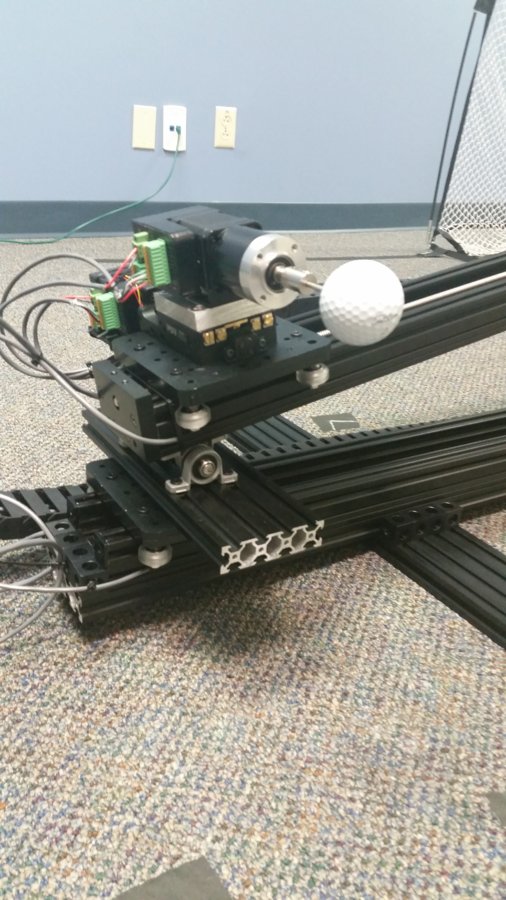
The below picture should give a pretty good glimpse of the +/- 15 degree goniometer with the angle markings on the side. Above that is a custom aluminum plate to attach the NEMA 17 motor mount to the goniometer. The original motor that came with the goniometer was replaced with the same iHSS42 closed loop stepper motor as the one driving the black and silver planetary gearbox also shown in this picture. The silver coupling on the gearbox shaft is the Actobotics 1/8" to 8mm coupling.
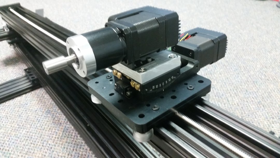
All the parts involved create a rather tall sandwich of metal in the following picture. Take note of the ball bearing pillow block between the two linear actuators:

Ball Trajectory Machine
Build in 'Everything Else' published by James Evanko, Nov 23, 2018.
Need to build a machine that accurately positions objects for processing by a computer vision algorithm? Here is an example of a machine that does that for a ball trajectory application. The black anodized V-rails work well for applications in optics and imaging where the machine needs to stay out of the limelight.
-
-
Build Author James Evanko, Find all builds by James Evanko
-
- Loading...
-
Build Details
- Build License:
-
- CC - Attribution - CC BY
Reason for this Build
Needed a way to capture images for a computer vision application with well known object displacements between images.Inspired by