
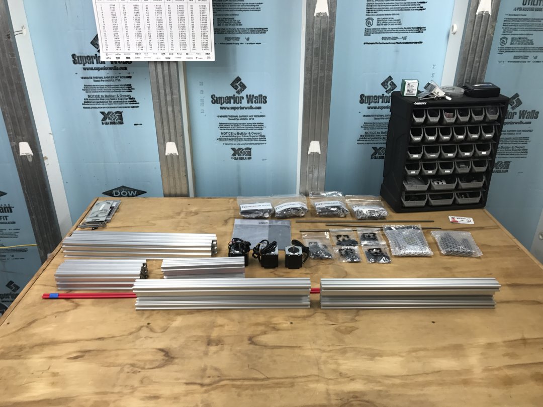
Arctic Stingray CNC BuildThe C-Beam bundle arrives...
I followed the Youtube video by Mark Carew during the assembly process.
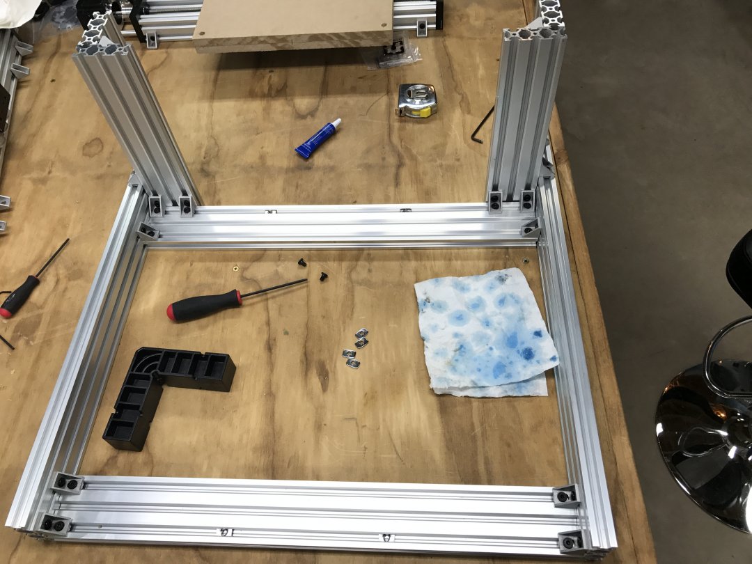
Be sure that all joints are square and that all fasteners are tightened using Loctite 242. This will keep the screw from coming loose from vibration during use.
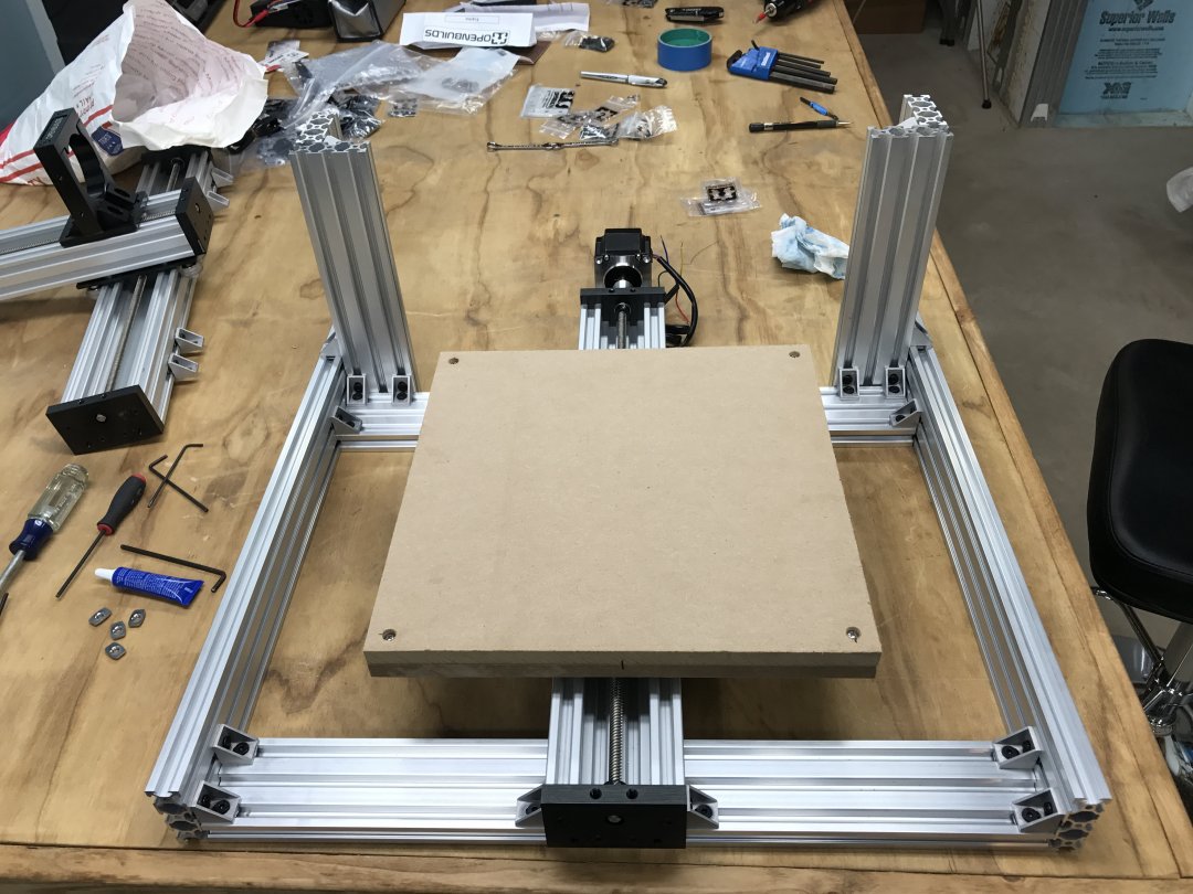
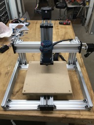
Basic C-Beam build complete...

I have started to add limit switches to the build. Two switches per axis using the Openbuilds Part Store - Micro Limit Switch Kit with Mounting Plate


You will need to use an M3 tap to tap the holes in the limit switch housing. Use the two button head M3 screws included in the kit to attach the limit switch to the mounting plate as shown below.


Next you will need to insert the M5 bolt included with the limit switch kit through the slot in the mounting plate. Now add an M5 washer. Apply a small amount of blue Loctite 242 thread locker to the threads of the M5 screw. Next spin on the M5 drop-in nut also supplied with the kit, but be sure only to spin on the nut far enough to keep it from falling off.


Drop this limit switch assembly into the lower groove of the Y axis and tighten. I added one to the front and one to the rear of the Y axis.

The X Axis limit switch is mounted differently using Openbuilds cast corner brackets and a standard M5 T nut (not supplied with the limit switch kit). Mount the limit switch to the flat mounting bracket as shown previously above using M3 screws. Attach the flat black mounting bracket to the cast iron bracket using the standard M5 T nut and M5 screw. Then in the lower slot drop in an M5 x 8 screw and add a small amount of blue Loctite 242 thread locker to the screw. Next turn on an M5 drop in T nut just far enough to keep it from falling off. Sit the limit switch bracket into position as shown below and tighten the M5 screw. Assemble another limit switch assembly and add it to the opposite side of the X axis.

Finally is the Z axis limit switch assembly.
This is assembled differently as well. You will use the standard Openbuilds limit switch kit as well as a 1/4" aluminum spacer and an end cap used for linear rails. You will need to take off approximately 3mm. I use a desktop belt sander and this makes the job quick and easy. Using the M3 tap as previously shown, tap the holes in the limit switch and fasten the switch to the flat black bracket using the M3 screws provided in the limit switch kit. Next you will use an M5 x 15 screw and put it through the slot in the black bracket. Now drop a 1/4" aluminum spacer over the M5 screw and then drop the end cap over the screw on top of the 1/4" aluminum spacer. Note that the side of the end cap that has been removed should be facing the limit switch. This allows you to tighten up the assembly without the end cap interfering with the limit switch.


Before mounting the switch assemblies I added (2) 1/4" aluminum spacers to the top of the Z Axis mounting bracket and (2) 1/4" aluminum spacers to the bottom of the Z axis end bracket. They were attached using Locitite 5 minute epoxy. These are used to stop the Z axis before breaking off the limit switch in case they fail. With these in place, move the Z axis fully to one end until it contacts the aluminum spacer. Move the axis off the spacer approximately 2mm. Now install the limit switch and adjust so that the switch lever is fully depressed. Repeat this on the other end of the Z axis.
Next I mounted my electrical enclosure to the bottom of the table fabricated to hold the CNC. This enclosure was salvaged from a dumpster at my work place which had been removed from service.

Now I started to assembly the electronic controls for the C-Beam CNC.
The enclosure has a backer plate that is used to mount the electronics to using standard DIN rail. First you must layout the panel so that you know where are the components will fit best on the backer plate. Once you know that you can start drilling and taping holes for M5 x 8 screws.

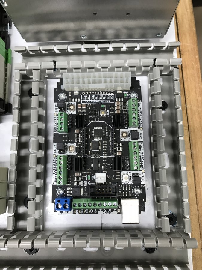
The main electronic component for this build is the controller board. I have decided to use the CNC XPro v3. I have used this in a previous build and it has worked without fail. I have designed a 3d printed DIN rail mount for the controller board. The design files and 3d printing files can be found in the files section of this build.


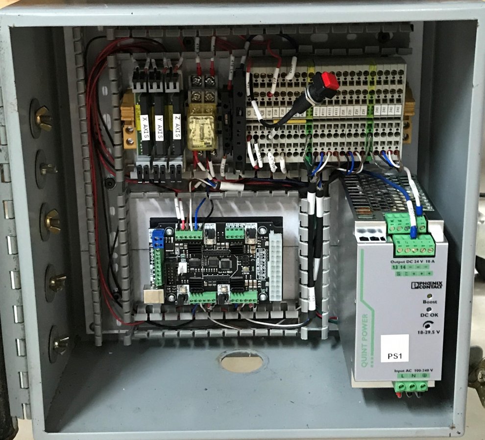
Following the mounting of the controller board I was able to mount the power supply, terminal blocks and relays. In the past I have found that a common problem with the axis limit switches was false trips. Now I install a relay that uses a 24vdc coil. I wire the circuit for the relay's coil through the limit switches on one axis. On the other side of the relay I wire the low voltage circuit from the CNC XPro v3. This way the low voltage circuit stays isolated within the electrical enclosure. The red push button shown below is the safety circuit reset button I wired in for testing.
Sometimes I can get a little carried away with cable management. I hate to have to worry about cables breaking because of repeated bending, pinching,etc. so, I have added remote wiring enclosures and cable chain. I started by adding a piece of extrusion to the back of the X Axis. This piece was 20mm x 40mm x 460mm and held in place with cast corner brackets. All parts can be purchased from the Openbuilds Parts Store. I also added a small piece of extrusion to the back of the Z Axis to hold the cable chain. See pictures below.


To hold the cable chain in place I tapped a hole in the end of the aluminum extrusion for an M5 screw. On the other end near the Z Axis I used T nuts and M5 screws to fasten the cable chain as well.


Next I added a small 4" x 6" x 2" enclosure to the back of the Z Axis extrusion support.
This was purchased from Radio Shack some time ago and since they have gone out of business. In my BOM I have cross referenced a different 4" x 6" x 2" enclosure.
This is used so that I can land my cables from the stepper motors and limit switches locally instead of having to patch cables together to make them long enough to get to the main electronics enclosure. The enclosure did not have a backer plate to mount the terminal barrier to so, I designed one and 3d printed it. I did not include this file in the files section because you are not able to buy them from Radio Shack. If anyone needs the file, feel free to contact me and I will gladly supply it.


After these items were in place I needed to add hole to the enclosure for the cable strain reliefs. Be sure to not have the backer plate/terminal barrier strip installed when drilling the holes. The bit may hit the backer plate during drilling. If possible, be sure to use a step bit for drilling the holes, it works so much easier. When the strain reliefs are installed, install the backer plate/terminal barrier. Now you can begin wiring.


Arctic_Stingray CNC
Build in 'Cartesian Style CNC' published by Catawissa_CNC, Jun 15, 2017.
This build is based on the C-Beam build by Mark Carew. I have added axis limit switches and a remote mounted control cabinet. This build also uses a custom moveable table.
-
-
Build Author Catawissa_CNC, Find all builds by Catawissa_CNC
-
- Loading...
-
Build Details
- Build License:
-
- CC - Attribution NonCommercial - CC BY NC
Reason for this Build
Wanted to have an aluminum plate cutterInspired by
Ox CNC - Mark Carew -
Attached Files:
Parts list
Qty Part Name Part Link Comments 1 C-Beam Machine Mechanical Bundle (1065-Bundle) http://openbuildspartstore.com/c-beam-machine-mechanical-... Link 1 Bosch PR20EVS Colt Palm Grip Router https://www.amazon.com/Bosch-PR20EVS-1-Horsepower-Electro... Link 1 40.55" Long - Black Cable Chain 18mm x 50mm https://www.amazon.com/gp/product/B00HR6EGQY/ref=oh_aui_d... Link 1 NBF-32004 - Plastic Enclosure http://www.newark.com/bud-industries/nbf-32004/enclosure-... Link 4" x 6" x 2" 1 8 pos. Barrier Strip https://www.amazon.com/a10073000ux0031-Position-Terminal-... Link 1 Linear Extrusion - 20x20x170 http://openbuildspartstore.com/v-slot-linear-rail/ Link 1 Linear Extrusion - 20x40x460 http://openbuildspartstore.com/v-slot-linear-rail/ Link 3 NEMA 23 Stepper Motors - #518 http://openbuildspartstore.com/nema-23-stepper-motor/ Link 6 Micro Limit Switch Kit with Mounting Plate - #745 http://openbuildspartstore.com/micro-limit-switch-kit-wit... Link -
Attached Files:

