Welcome to Our Community

Some features disabled for guests. Register Today.

WorkBee CNC Machine

Discussion in 'CNC Mills/Routers' started by Ryan Lock, Sep 21, 2017.
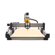
  1. Giarc

    Giarc OpenBuilds Team
    Staff Member Moderator Builder Resident Builder

    Joined:
    Jan 24, 2015
    Messages:
    2,921
    Likes Received:
    1,620
    Well, now you can salvage the bent screw, cut it, and make a 3D printer and a Mini mill.;) You wouldn't want to waste it.
     
  2. GrayUK

    GrayUK Openbuilds Team Elder
    Staff Member Moderator Builder

    Joined:
    May 5, 2014
    Messages:
    1,668
    Likes Received:
    627
    Or a couple of spare "Z Axes" :D
     
  3. Jim.....

    Jim..... New
    Builder

    Joined:
    Dec 31, 2017
    Messages:
    11
    Likes Received:
    17
    Hi all,
    Extream newbie with my just finished WorkBee.
    Great Forum, made build a lot easier!
    R0005389.JPG
    Best,
    Jim.
     
  4. Awestruck

    Awestruck New
    Builder

    Joined:
    Dec 17, 2017
    Messages:
    76
    Likes Received:
    13
    Nice work @Jim..... What will you be making with your CNC?
     
  5. Jim.....

    Jim..... New
    Builder

    Joined:
    Dec 31, 2017
    Messages:
    11
    Likes Received:
    17
    Thank you,
    Hoping to get to grips with some simple boat name plaques among other things. We do a lot of local commercial fishing boat reg numbers in vinyl and this would be a nice additional service to offer.
     
    jmac80 likes this.
  6. Ryan Lock

    Ryan Lock Veteran
    Builder

    Joined:
    Oct 12, 2014
    Messages:
    530
    Likes Received:
    292
    Hey everyone,

    A lot of activity hear recently, i have been off for the last week or so, so sorry if i haven't been replying to queries.

    @Jim..... Thanks for the picture looking good!

    @Kyle Barrett Did you get your issue sorted?

    @michielproce Could you take the screw out and see if it is bent? We can replace it if needed

    If i have missed anyone queries send me a PM

    Ryan
     
    Yellers likes this.
  7. Kyle Barrett

    Builder

    Joined:
    Dec 5, 2017
    Messages:
    28
    Likes Received:
    10
    Jim Great work.

    Ryan, I believe I got my issue sorted. I changes units to inches in UGS and Aspire. And I also found that my Z axis wasn't low enough and Aspire pre programed a safe limit of something like 12mm which was tripping the kill switch. I was also trying to cut and 18mm piece of wood. Not a good one to start with. If I keep the safe Z travel about 6 mm off the surface all is good. Also removed a M6 line in my Gcode which was triggering a Error 20 in UGS. Thats a tool change function which is not supported. So now its just down to hooking up a vacuum and I'll be digging in.

    Thanks to all who lent a hand.
     
    Ryan Lock and Jim..... like this.
  8. jmac80

    jmac80 New
    Builder

    Joined:
    Oct 12, 2017
    Messages:
    3
    Likes Received:
    2
    Hi all
    looking to order up a workbee soon,

    Has anyone fitted a spindle to theirs? If so what one?
    Would much rather go down the spindle route due to noise and not having to mess with changing brushes etc.
    I do have the dewalt router already (had it a few years now) But wow it's noisy!
    also, anyone fitted a laser on theirs for engraving? can it be done?

    Cheers James
     
    #158 jmac80, Jan 1, 2018
    Last edited: Jan 1, 2018
    Ryan Lock likes this.
  9. Spark Concepts

    Spark Concepts Journeyman
    Builder

    Joined:
    Dec 17, 2013
    Messages:
    131
    Likes Received:
    107
    Very nice build Jim!

    @Kyle Barrett: Glad to hear things are sorted, please reach out if you need anything else! We are getting our installs of Aspire and Vcarve up and running so I should be able to help a bit more with that in about a week.

    @jmac80: Welcome! I currently have a 2.4kW spindle/VFD on one machine and a 400W spindle on another (previously had one with a dewalt on it , and one with a no-name router). The VFD is super quite, expensive, and will probably need a custom mount. I have no complaints about the cuts but I would recommend running the spindle speed directly from the VFD as it lets you adjust speed real-time. The 400W spindle is OK, it is relatively cheap, rather quiet as well, and can print a bushing to use it with the stock mount. It does get bogged down when cutting polycarb or hard wood but it does ok. If you run a dust collector the vacuum will be louder than both these spindles. All in all, on the next build I will probably go back to the dewalt though. For laser engraving Jtech photonics makes a laser that is compatible and has a 3D printed bracket to attach to the front of the stock router mount (haven't used one but get a lot of people who do).
     
    jmac80 likes this.
  10. michielproce

    Builder

    Joined:
    Mar 23, 2017
    Messages:
    15
    Likes Received:
    5
    I'll cut it in half and make a wobbly 5-axis Workbee ;)

    Ryan (Ooznest) has very generously offered to sent me a new axis! I'll be cutting again in no-time :D
     
    Ryan Lock likes this.
  11. jmac80

    jmac80 New
    Builder

    Joined:
    Oct 12, 2017
    Messages:
    3
    Likes Received:
    2
    Anyone looked at the 840 stepcraft cnc machine? it's either that or a workbee 1mx1m for me,
    I like how the step craft has add ons for 3d probe, tool changer, laser, tool length etc.. but is it worth it?
     
    Ryan Lock likes this.
  12. Jim.....

    Jim..... New
    Builder

    Joined:
    Dec 31, 2017
    Messages:
    11
    Likes Received:
    17
    All,
    I wonder, what is your preferred method of attaching your wasteboard to your Workbee rails? I have used method one from the manual which is the higher setting, any suggestions for me as this is all very new to me.
    Thank you,
    Jim.
     
  13. Kyle Barrett

    Builder

    Joined:
    Dec 5, 2017
    Messages:
    28
    Likes Received:
    10
    my spoiler board is over 18 mm thick. was an inch when I started. I drilled a pocket down about half way and then used a drill to make a small drill hole. I then put a new M5 screw down through the board and used a drop in tee nut to attach. I have one in each corner. I also squared everything up to. Can't wait to start cutting.
     
  14. Jim.....

    Jim..... New
    Builder

    Joined:
    Dec 31, 2017
    Messages:
    11
    Likes Received:
    17
    Of course, drop in tee nuts,,, thank you Kyle.
     
  15. Ryan Lock

    Ryan Lock Veteran
    Builder

    Joined:
    Oct 12, 2014
    Messages:
    530
    Likes Received:
    292
    You can use M5 Bolts and drop in tee nuts.

    Ryan
     
  16. Jim.....

    Jim..... New
    Builder

    Joined:
    Dec 31, 2017
    Messages:
    11
    Likes Received:
    17
    Thank you guys.
     
  17. Kyle Barrett

    Builder

    Joined:
    Dec 5, 2017
    Messages:
    28
    Likes Received:
    10
    Not sure if you can see them but I took a few pics., My board is 48" wide by 50" deep. One M5 in each corner. Holds it down nice. Next step is I'm going to surface the top to make it nice and smooth. It got a bit banged up just me moving around.
     

    Attached Files:

    Ryan Lock and Jim..... like this.
  18. Awestruck

    Awestruck New
    Builder

    Joined:
    Dec 17, 2017
    Messages:
    76
    Likes Received:
    13
    Nice! So there were plenty of extra drop in tee nuts in the kit to attach the waste board?
     
  19. Kyle Barrett

    Builder

    Joined:
    Dec 5, 2017
    Messages:
    28
    Likes Received:
    10
    I got the full kit and I had an entire extra bag. I think it's intentional :) At over 18m its pretty high so my z-travel is really restricted. But as I mill the table down more I'll be able to cut thicker items. I struggled to cut a board that was 3/4".

    When I surface the table I may take of 4-6mm/ .25 inch.

    My unit conversions jump around alot as I'm more accustom to inches although here in canada we should be using metric. Not sure what most folks use on this forum. :eek:
     
  20. Ryan Lock

    Ryan Lock Veteran
    Builder

    Joined:
    Oct 12, 2014
    Messages:
    530
    Likes Received:
    292
    Yes there is lost of extras, as they are so handy to have, especially if you forget to insert a normal tee nut :banghead:

    Ryan
     
    jmac80 likes this.
  21. jmac80

    jmac80 New
    Builder

    Joined:
    Oct 12, 2017
    Messages:
    3
    Likes Received:
    2
    Hi Ryan
    On the ordering page for the workbee black anodised is an option, Is that the actual long rails etc, so would kind off look like an xcarve?
     
  22. Ryan Lock

    Ryan Lock Veteran
    Builder

    Joined:
    Oct 12, 2014
    Messages:
    530
    Likes Received:
    292
    Hi,

    Yes that is correct!

    Ryan
     
    jmac80 likes this.
  23. Jim.....

    Jim..... New
    Builder

    Joined:
    Dec 31, 2017
    Messages:
    11
    Likes Received:
    17
    Wow, what a machine! Well, that's me hooked.
    My first carve.
    IMG_1192[1].JPG
     
  24. Ryan Lock

    Ryan Lock Veteran
    Builder

    Joined:
    Oct 12, 2014
    Messages:
    530
    Likes Received:
    292
    @Jim..... Nice carve there! What diameter bit did you use to get the detail?
     
  25. Jim.....

    Jim..... New
    Builder

    Joined:
    Dec 31, 2017
    Messages:
    11
    Likes Received:
    17
    Ryan,
    1/8 inch ball from starter kit!
     
    Ryan Lock likes this.
  26. T4Concepts

    T4Concepts Journeyman
    Builder

    Joined:
    Dec 7, 2017
    Messages:
    108
    Likes Received:
    114

    Nice pic and well done Jim ......... must be real happy with that.
    I just ordered my full WorkBee kit from Ryan at Ooznest just before Christmas, can't wait to get stuck in :D

    Just one question though guys .............. why is it every cnc build I see has the motor/spindle mount so far up the Z axis ? same as Jim has on his assembly.
    When I receive my WorkBee I'll be trying to install the spindle mount right at the end of the Z axis, hopefully that should give me a little more cut depth, or is that not recommended due to stability ?

    BTW, really impressed with your carving of the boat Jim :thumbsup:


    TURK
     
  27. Jim.....

    Jim..... New
    Builder

    Joined:
    Dec 31, 2017
    Messages:
    11
    Likes Received:
    17
    Turk,
    In the manual it shows two settings to mount the spoiler board. I chose the higher method one setting but I think I may change to the method two so to have a greater Z range.
     
  28. Awestruck

    Awestruck New
    Builder

    Joined:
    Dec 17, 2017
    Messages:
    76
    Likes Received:
    13
    @T4Concepts / TURK -

    Think of the Z axis, include the router/spindle and the bit as a large lever on the gantry. When the Z axis is down, router is low and bit is driving into material, there will be a force on the gantry. So I suspect what you are observing is trying to keep rigidity by mounting the router/spindle a little higher on the extrusion. It is still a level. The key is to be careful that the bit and material height doesn't interfere with the extrusion used on the Z axis.

    Also, just as Jim mentioned too, you can configure the height of the spoiler board when you build your unit.
     
  29. Ryan Lock

    Ryan Lock Veteran
    Builder

    Joined:
    Oct 12, 2014
    Messages:
    530
    Likes Received:
    292
    @T4Concepts The position of the router on the Z-Axis extrusion doesn't really effect the max cutting depth, the max cutting depth is determined by the distance between the underside of the Z-Axis and spoilerboard. Then router needs to be mounted in a position to take advantage of this. For instance if you wanted to cut the full max depth, then you need the router positioned the cutting bit is sticking out below the underside of the Z-Axis the exact cut depth.

    Also the ideal situation, would be to have the material mounted as close to the router as possible, then you are minimizing the cantilever distance when cutting.

    Ryan
     
  30. Giarc

    Giarc OpenBuilds Team
    Staff Member Moderator Builder Resident Builder

    Joined:
    Jan 24, 2015
    Messages:
    2,921
    Likes Received:
    1,620
    Another limit to depth of cut is finding longer endmills. I calculated out my build and got the max z I could reasonably get. Then when I went to drill holes on my spoil board for threaded inserts, I discovered I needed to order extra long endmills which were 2.5 inches with a 1 inch cutting edge.
     
    Spark Concepts likes this.

Share This Page

  1. This site uses cookies to help personalise content, tailor your experience and to keep you logged in if you register.
    By continuing to use this site, you are consenting to our use of cookies.
    Dismiss Notice