Welcome to Our Community

Some features disabled for guests. Register Today.

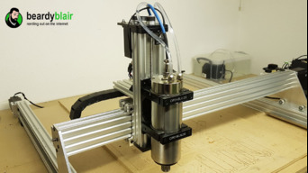
Sphinx XL

Discussion in 'CNC Mills/Routers' started by beardyblair, Nov 18, 2016.

  1. Rosenwasser Benny

    Builder

    Joined:
    Mar 21, 2017
    Messages:
    21
    Likes Received:
    2
  2. Kyo

    Kyo Veteran
    Staff Member Builder Resident Builder

    Joined:
    Feb 27, 2014
    Messages:
    673
    Likes Received:
    701
    Hello Benny,
    I do have files for a 50mm taller side plates. I hope these are helpful sketchup .skp file attached. :thumbsup:
     

    Attached Files:

  3. Rosenwasser Benny

    Builder

    Joined:
    Mar 21, 2017
    Messages:
    21
    Likes Received:
    2
    Thanks a lot Kyo, this should be enough !
     
  4. beardyblair

    beardyblair Well-Known
    Builder

    Joined:
    Aug 1, 2016
    Messages:
    59
    Likes Received:
    72
    What a guy!

    I just ordered the plate and gearing to make the upgrade to mine. will update build log with images once complete.
     
  5. pmyrie

    pmyrie New
    Builder

    Joined:
    Oct 9, 2015
    Messages:
    3
    Likes Received:
    0
    hi
    Any chance you have the taller plate files for fusion 360
     
  6. beardyblair

    beardyblair Well-Known
    Builder

    Joined:
    Aug 1, 2016
    Messages:
    59
    Likes Received:
    72
    @Kyo has attached them for sketchup above. Import them into Sketchup (free) and then export them in a file format F360 uses. If you get stuck I can help you tonight, currently in a park with no access to f360 lol.
     
  7. Andrew Law

    Builder

    Joined:
    Mar 30, 2016
    Messages:
    2
    Likes Received:
    1
    Hi These 3mm Stainless steel plates were purchased from myself Andy Law on ebay. My ebay user ID is law2043 I can see why there might be some confusion with Chris Laidlaw. Its good to hear you were happy with your purchase

    I am also selling 5mm 304 hot rolled stainless steel Kyo plates for those interested.-

    5mm Stainless steel Openbuilds Kyo Sphinx CNC Router Plates Extra LARGE

    Cheers guys keep up the great work.
     
  8. beardyblair

    beardyblair Well-Known
    Builder

    Joined:
    Aug 1, 2016
    Messages:
    59
    Likes Received:
    72
    I purchased mine from @Chris Laidlaw - Ebay user id: chrisclub1 although I did go direct. Are you refering to someone else purchasing your plates?
     
  9. Rosenwasser Benny

    Builder

    Joined:
    Mar 21, 2017
    Messages:
    21
    Likes Received:
    2
    After getting prices from local workshops, also I did my purchase at Chris Laidlaw.
    It seems that the prices in Belgium ale much higher than when I buy in the states (transport and customs included)
    Because the X of my cnc is about 1 meter, and to be absolutely sure it is strong and stiff enough, I have chosen to buy the 6 mm plates Chris Laidlaw.
    Regards, Benny
     
  10. Andrew Law

    Builder

    Joined:
    Mar 30, 2016
    Messages:
    2
    Likes Received:
    1
    William Hensman likes this.
  11. beardyblair

    beardyblair Well-Known
    Builder

    Joined:
    Aug 1, 2016
    Messages:
    59
    Likes Received:
    72
    Ahh I now see the confusion! My bad - please blame the beer and accept my apologies. I did purchase from Chris but it seems I linked to your kits! gotya
     
  12. Electric Norseman

    Builder

    Joined:
    Apr 16, 2017
    Messages:
    1
    Likes Received:
    0
    I'm considering building this machine, what is the actual machining area?
     
  13. ChadRat6458

    Builder

    Joined:
    Dec 10, 2014
    Messages:
    93
    Likes Received:
    24
    What size steppers did you use? How fast will it cut wood? Any videos of it in action? Thanks.
     
  14. beardyblair

    beardyblair Well-Known
    Builder

    Joined:
    Aug 1, 2016
    Messages:
    59
    Likes Received:
    72
    Bed area is 1000mm x 920mm
    Cutting area is ~850mm x 840mm, this is dependant on your spindle and skirt if you are using an extractor.

    I used massive 3A 345oz NEMA 23 motors. These are powerful enough to tear things to pieces!

    Speed is a tough one as it depends on what size bit, depth of cut, type of bit, type of cut and wood you are cutting.

    There is a lot of info out there and even online and offline calculators that can help. I usually start off slow and speed things up as I monitor my piece.
    The bit should be cutting not burning the wood so chip removal and a good bit are essential.

    I have managed to cut MDF at up to 600 IPM.

    Use down cut bits wherever possible with wood to preserve the top surface.

    Some handy links:
    CNC Routing Basics: Toolpaths and Feeds 'n Speeds | Make:

    https://www.shopbottools.com/ShopBotDocs/files/FeedsandSpeeds.pdf
     
  15. ChadRat6458

    Builder

    Joined:
    Dec 10, 2014
    Messages:
    93
    Likes Received:
    24
    Thanks for the reply. Do you have in video of it in action? I hope to get my plates later this month.
     
  16. beardyblair

    beardyblair Well-Known
    Builder

    Joined:
    Aug 1, 2016
    Messages:
    59
    Likes Received:
    72
    Think we are cutting tomorrow so will look to film something then :D
     
  17. Corey Carlson

    Builder

    Joined:
    Jun 12, 2017
    Messages:
    4
    Likes Received:
    1
    So I just started gathering pieces for my first build, this machine look to be exactly what I wanted. I'm still learning and very undecided on the electronics. I'm leaning towards the Gecko system with USB option, what's everyone's thoughts?
     
  18. ChadRat6458

    Builder

    Joined:
    Dec 10, 2014
    Messages:
    93
    Likes Received:
    24
    I think the gecko system is expensive. I like individual drivers. I have had good luck with the Keling KL-4030 driver. I connect my pc to a break out board. c10 with a parallel port. I run LinuxCNC. I think I will go with the Mesa card setup for my next machine. The electronics was the hardest part for me to figure out.
     
  19. Corey Carlson

    Builder

    Joined:
    Jun 12, 2017
    Messages:
    4
    Likes Received:
    1
    I had come across an interesting board, a fella was making them and he had a website, they looked really good but I can't for the life of me find it again lol
     
  20. ChadRat6458

    Builder

    Joined:
    Dec 10, 2014
    Messages:
    93
    Likes Received:
    24
    My first electronics setup had a board with the drivers build into it. I burned out one of the drivers. At that point, I was tired of messing with grbl and the driver board. I got the kelings and went with LinuxCNC. I could not be happier.
     
  21. beardyblair

    beardyblair Well-Known
    Builder

    Joined:
    Aug 1, 2016
    Messages:
    59
    Likes Received:
    72
    I looked at Gheko but its really expensive for what it is. There are Chiesium options that outperform them for a lot less. If I were to do it over (next build) I would use KYO's board but with the same drivers I have mentioned earlier in this thread.
     
  22. beardyblair

    beardyblair Well-Known
    Builder

    Joined:
    Aug 1, 2016
    Messages:
    59
    Likes Received:
    72
    This CNC machine has been going for a while now and has not missed a beat. It does however have some shortcomings and a few things I would like to improve on.
    I already upgraded the Z axis to use a 1:1 belt so I could lower the overall height of the machine as I plan to build an enclosure.

    Proposed upgrades / modifications:
    • Upgrade the spindle to a 2.2KW version with VDF to allow presise spindle speed control and the use of a better collet system.
    • Change 1:1 belt drive on the Z axis to be 3:1 or 4:1 to improve resolution as I sometimes use the machine to make PCB's and help take the weight of the larger spindle!
    • Add a probe (currently deciding on type)
    • Change monitor bank to touch screens as I have a few machines now and trying to remember the correct mouse is a pain when in a hurry.
    • Possibly change to Mach 3/4 control software. No major issues currently but heard good things.
    • Build an enclosure with viewing window. I cut a LOT of carbon and it is a pain to keep the workspace clean. Also have a BIG MDF project coming up soon so dont want that headache.
    • Get a dedicated extraction system to use with enclosure and dust shoe.
    • Add an air nozzle to help when cutting aluminium.
    • Possibly change the controller from the protoneer to something else. @Kyo ????
    Looking for opinions and advice as always! I have already bought the 80mm 2.2KW spindle and VDF so intend to fit that tomorrow! Pics coming soon!
     
    GrayUK likes this.
  23. Kyo

    Kyo Veteran
    Staff Member Builder Resident Builder

    Joined:
    Feb 27, 2014
    Messages:
    673
    Likes Received:
    701
    All my machines now run This Grbl USB Controller With a screw terminal board Like this unit "Here" I am able to run pretty much any Stepper driver. From Gecko's to the OB DQ542MA units. If moving away from grbl check out the Mesa 7i76E + Linuxcnc. I am in the process of setting up a few industrial control cabinets with this unit and so far have been very impressed.

    I look forward to updates on the 2.2Kw spindle.. I have been getting a lot of questions as of late on how a heavier spindle such as that will preform with the Sphinx design. It will be nice to have real world numbers vs my assumptions on the matter. :thumbsup:
     
  24. beardyblair

    beardyblair Well-Known
    Builder

    Joined:
    Aug 1, 2016
    Messages:
    59
    Likes Received:
    72
    Upgrade 1: Spindle
    I purchased a Huanyang 2.2KW VFD (vairable frequency drive) and spindle from eBay as it had some good reviews, came with "everything" and was the right price (cheap). This was to replace my Dewalt spindle as I felt it was too loud, under powered and had a lack of tooling available. Control was also an issue.

    So first thing was to mount the spindle, to be honest I thought this would be the hardest part of the process. It "turned" out to be the easiest!
    I simply enlarged two Openbuilds 73mm holders to 80mm using my lathe. If you intend to do this use two 5mm spacers and clamp the front plate in place (also but something soft on the jaws!) and center it in a 4 jaw.

    This worked a treat and in my opinion is a better solution to the 3D printed versions people have done elsewhere.


    [​IMG]

    I mounted them to the backplate with 2 angle brackets per mount. I will possibly be adding another 2 to each bracket to stiffen it further depending on the back plate I end up using. There is no play here, the motors have no issue and I did not see any noticeable deflection. There is however still a twist on the Z axis when applying pressure on the X plane. I have a plate designed to fix this.

    [​IMG]

    Next up was to wire up the VFD. The instructions were written in english and fairly technical. If you are not electronically inclined its a tough read. As always, the internet was filled with many how-to's and provided me with all the help I needed. So here is what I took from it all and my instructions incase I need to reset or rebuild. Please note that I am in the UK and am using 240v single phase AC power and for now I will be controlling it from the VFD.

    Remove the lower plate on the front of the VFD unit. Connect power cable to the lower terminal bar. Positive to R, negative to S and earth(ground) to E. I used 13A rated flex. Do not connect the spindle wiring yet.

    Program the VFD for your spindle (note: my settings are shown).

    To enter the programming mode press "PRGM", you will then see a parameter entry eg PD001. To move between or select a parameter use the up and down keys to change the value
    of the digit, the shift key to move to the next digit and then SET to select and go "into" a parameter. Its current value will then be shown. Use the same method to change and set its value.

    First thing, reset the settings. Very important, mine was not "factory" or correct for the spindle. To do this change parameter PD013 to 8 and then press SET. Your VFD is now reset.

    Next adjust the following parameters to match your spindle, you can use the manual and set up "everything".

    PD001 0 (0 as I am using the front control knob for now)
    PD002 1 (Set to 1 as I am using the control knob for now)
    PD003 400 (Main frequency - set this to your spindle frequency)
    PD004 400 (Base frequency - set this to your spindle frequency)
    PD005 400 (Max frequency - set this to your spindle frequency)
    PD006 400 (Intermediate frequency - set this to your spindle frequency)
    PD007 0.50 (Min frequency)
    PD008 220 (Max spindle voltage - not input voltage)
    PD009 13 (Middle spindle voltage)
    PD010 6.5 (Low spindle voltage)

    PD072 400 (High-end analogue frequency - your spindle frequency)
    PD072 120 (Low-end analogue frequency - your spindle frequency)

    PD141 220 (Rated motor voltage)
    PD142 10 (Rated motor amps)
    PD143 4 (Number of motor poles)
    PD144 3000 (RPM at 50Hz. Since the max RPM is 24000 at 400Hz, this means that the RPM at 50Hz will be 3000)

    With the spindle mounted and VFD programmed I set up a temporary cooling loop. I used the supplied submersible pump set in a storage box and some 5mm clear tube I had a reel of. I intend to build a larger dedicated system for use ith a few of our machines with heat exchanger that will dump the heat into the communal part of our offices where it is always cold.

    [​IMG]

    And finally its time to wire up the spindle. Use terminals 1, 2 and 3 on the spindle. If you have plumbed in the cooling do not remove the top of the spindle to check anything as it will fill the motor with water! The socket is numbered. Terminal 4 is not wired in. I used 14AWG wire as I had a 3 core shielded cable available, this is overkill. Connect to the U, V and W terminals on the VFD in any order, once operational if it is running in the wrong direction just swop any two wires.

    Now before anyone says anything about grounding. I have a ground loop that connects everything except the spindle at the moment. I intend to rehouse all the electrics and then ground the spindle to the X gantry. You can run a ground from the spindle body to the earth on the VFD, this has been recommended elsewhere.

    [​IMG]

    [​IMG]

    And here it is all assembled and ready for use. Lots of cutting to be done on Monday so will report back then.

    [​IMG]
     
    mikework, Mark Carew, GrayUK and 3 others like this.
  25. Peter Van Der Walt

    Peter Van Der Walt OpenBuilds Team
    Staff Member Moderator Builder Resident Builder

    Joined:
    Mar 1, 2017
    Messages:
    14,715
    Likes Received:
    4,256
    Nice one!
     
    swohnrade likes this.
  26. Angus Shippey

    Builder

    Joined:
    Jul 20, 2017
    Messages:
    6
    Likes Received:
    1
    Hi Beards

    I'm loving your build, mine is very similar.

    Please could you post the files you used to 3d print the brackets to fix the angle to your x axis for the drag chain.

    Regards Angus
     
  27. Michael.M

    Michael.M Veteran
    Staff Member Builder Resident Builder

    Joined:
    Jan 21, 2017
    Messages:
    432
    Likes Received:
    265
    Awesome! That spindle looks to be no bigger than my 800w. 65mm?
     
  28. beardyblair

    beardyblair Well-Known
    Builder

    Joined:
    Aug 1, 2016
    Messages:
    59
    Likes Received:
    72
    Its a 80mm spindle. Although I have taken a bit off the OB clamps there is no movement and I am really happy with the results. Will be testing on alloy this week.
     
  29. beardyblair

    beardyblair Well-Known
    Builder

    Joined:
    Aug 1, 2016
    Messages:
    59
    Likes Received:
    72
    There ya go Angus.
     

    Attached Files:

  30. Angus Shippey

    Builder

    Joined:
    Jul 20, 2017
    Messages:
    6
    Likes Received:
    1
    Thank you kind Sir
     

Share This Page

  1. This site uses cookies to help personalise content, tailor your experience and to keep you logged in if you register.
    By continuing to use this site, you are consenting to our use of cookies.
    Dismiss Notice