Welcome to Our Community

Some features disabled for guests. Register Today.

Sphinx 55 with 3D Printed Addons

Discussion in 'CNC Mills/Routers' started by David Bunch, Nov 28, 2018.
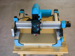
  1. David Bunch

    David Bunch Veteran
    Builder

    Joined:
    Oct 27, 2014
    Messages:
    622
    Likes Received:
    428
    I remixed a soldering jig to use machine screws to hold the wire while tinning them. My thought on using the screws was mostly to dissipate the heat from the soldering iron, but is probably far enough away not to hurt it. I will try it without the screws tomorrow to see if it makes any difference. I did 2 wires today to test it & the screws held the wire well & I did not see any damage to the insulation from holding them. Solder Screw Fingers by GeoDave
    IMG_6241_800x600.jpg IMG_6242_800x600.jpg
     
  2. David Bunch

    David Bunch Veteran
    Builder

    Joined:
    Oct 27, 2014
    Messages:
    622
    Likes Received:
    428
    I moved my Sphinx CNC to its new home in the shed Friday, a little earlier than I planned. We are redoing some of the floors in the house & needed to move it out of the way. I am planning to build an enclosure around it after I finish the wiring. BTW, those Hakko Professional Quality 20-30 AWG Wire Strippers I got from adafruit work really well.

    For the enclosure, I am going to start off with a wooden frame with slots to hold the partitions. For the partitions, I am going to start off with trying 6 sheets of 20x30 foam core for the sides since they are only $1 each at dollar store, but the wood will be slotted so I can change that to another material if that does not work. I am using MakerSL MSL-21 OB Minimill Enclosure layout as a starting point for the design. The frame will probably be 2x4's ripped in half which is less expensive than 2x2's, but will check prices today.
    IMG_6244_800x600.jpg
     
  3. David Bunch

    David Bunch Veteran
    Builder

    Joined:
    Oct 27, 2014
    Messages:
    622
    Likes Received:
    428
    I needed my 250mm length of 2040 for another project, so I decided to change the corners that attach the electronics case to the back v-slot to a single plastic part on each side. I made the V-slot plastic part 4mm thick where the T-nut grabs & added a little distance inside for a M5x20mm screw to pass thru. I only added 2 v-slot cavities to the plastic part, but only really needed 1. I added V2040_90_2x_Rev12.stl to the Files and Drawings tab. Here is what those 2 corners look like. This also takes up less space horizontally on the back of the machine as compared to that 250mm length of 2040 I was using.
    IMG_6410_800x600.jpg IMG_6411_800x600.jpg IMG_6412_800x600.jpg IMG_6413_800x600.jpg IMG_6414_800x600.jpg
     
  4. David Bunch

    David Bunch Veteran
    Builder

    Joined:
    Oct 27, 2014
    Messages:
    622
    Likes Received:
    428
    I added the file Sphinx55_3D_Addons.zip to the Files and Drawing tab that should be all the plastic parts that I used on this build. If I add any more to the build, I will upload a newer version of that .zip file. This file includes all the .stl & .scad source files I used. Some of these are also on thingiverse which I mentioned in previous posts. There are several .stl & the SphinxText_Rev3.scad that are only used for reference in the .scad files and do not need to be printed. The .stl files used for reference are: FacePlateArcs.stl, Spade_Connector.stl, C-Beam_End_Mount.stl, GT3_20T_TimingPulley.stl, NEMA23_ReductionPlate_C-Beam.stl, C_Beam_1mm.stl, V2080_1mm.stl, Sphinx_Y_Plate_WithM5Heads_Rev1.stl, xPRO_Board_V3.stl, LimitSwitch.stl. Several of the .scad files may take a while to run, especially the Hull_Side_Rev59.scad which is used for the electronics case. This is because of the hull() commands I used mostly. My PC is 8 years old, so your machine may run these a bit faster.
     
  5. David Bunch

    David Bunch Veteran
    Builder

    Joined:
    Oct 27, 2014
    Messages:
    622
    Likes Received:
    428
    I updated the zip file of all my parts to Sphinx55_3d_Addons_V2.zip. I added CBeam3mmSpacerKeeper_Rev40.stl & scad file that I had forgot to add before which is shown on the 12/17/2018 build log entry. That little part covers the 4 - 3mm spacers on the end of the x-axis C-Beam. I also changed the electronics case to move the internal wire ties to better locations. You will notice from the attached photo that they could have been in better locations for routing the motor/limit switch wiring. The other version should still work and I do not plan to reprint this, but changed it for cleaner routing for those that will print it. I also adjusted that openscad file to be a little cleaner on the final STL file. The image shows Hull_Side_Rev58.stl. The newest version is now Hull_Side_Rev61.stl

    IMG_6423_800x600.jpg
     
    GrayUK likes this.
  6. David Bunch

    David Bunch Veteran
    Builder

    Joined:
    Oct 27, 2014
    Messages:
    622
    Likes Received:
    428
    Now that it is warm enough in my shed this week, I cut one motor wires back & tinned the ends late yesterday. I expect to get the rest of the wires cut back & tinned today. I made a modification to my Solder Screw Fingers remix to add the use of a vertical M6 screw. I have a few of those M6 screws I retrieved from esun filament spools. I could make this design a little easier to use by adding a plastic part to screw down on the wire. Since I am only doing about 20 wires this works well. I just tighten the screw down slowly and pull on the wire after each 1/4 turn or so until it is snug enough without damaging the insulation. That modified screw finger is the file SolderScrewFingers_M6_2x_Rev23.stl I tinned the ends longer than needed so I would not burn the insulation & will cut them back to correct end length before attaching to electronics. I am leaving about 6"-7" of extra length on each wire in case I need to move it a little. The X-axis is actually has no extra wire, so I do have to leave the case closest to that side of the machine for it to fit well. I think openbuilds should take a look at the length of wire in the wiring kit for the X-axis as they have it the same length as the 2 - Y axis wires which are a lot closer to the electronics than the X. Seems like an extra 6" would give it a little extra room. I have some extra 7' wires that came with the motors & would have used them if I had realized that before. Since they do reach, don't think I will bother changing them out.

    I also discovered a while back the idea of using blue tape to pick up all the bits & pieces of small wire to help dispose of those wires easier. I Just fold the tape back on itself before throwing it in the trash can. I am using colored electrical tape I got from Lowes awhile back to color code the different motor/limit switch wires. Red for X, Green for Y, blue for Z, Yellow for A Axis. I was going to use White for LED, but may not bother coding that wire. I used a razor blade to cut the outer insulation back. Think I got those blades from dollar tree. Here are some photos.
    IMG_6425_800x600.jpg IMG_6426_800x600.jpg IMG_6427_800x600.jpg IMG_6428_800x600.jpg
     
  7. David Bunch

    David Bunch Veteran
    Builder

    Joined:
    Oct 27, 2014
    Messages:
    622
    Likes Received:
    428
    Think I got all the wiring redone today. I had to re-strip & tin a couple of wires that did not look good on my 1st try. That is another good reason to leave 6" or so extra wire. The little extra wire also helps when wiring the xPro out of the case. I had bought a PCB clamp holder from adafruit earlier this year & it really came in handy for wiring this board up while keeping it close to its mounting location. I will double check the wires tomorrow before powering it up again. I had a photo of the wiring I did before shortening the wiring which was very helpful for reference without having to re-watch the build video. I made a little plastic jig for cutting the ends of the wires to the correct length. It worked well for me. It is a very simple jig & can be seen in the 1st 2 photos. The jig is shown with all 4 motor wires in it, but I only put one wire in at a time when cutting as it was easier to make sure it was the correct length.
    IMG_6433_800x600.jpg IMG_6434_800x600.jpg IMG_6445_800x600.jpg IMG_6446_800x600.jpg
     
  8. David Bunch

    David Bunch Veteran
    Builder

    Joined:
    Oct 27, 2014
    Messages:
    622
    Likes Received:
    428
    I wire tied the wiring yesterday & might redesign those 2 Y-motor connect covers to have a way to wire tie to the back bottom aluminum spacers. I have to clean off my work bench beside the Sphinx before I test it again.
    IMG_6454_800x600.jpg IMG_6455_800x600.jpg IMG_6456_800x600.jpg IMG_6457_800x600.jpg IMG_6458_800x600.jpg IMG_6459_800x600.jpg
     
  9. David Bunch

    David Bunch Veteran
    Builder

    Joined:
    Oct 27, 2014
    Messages:
    622
    Likes Received:
    428
    I am considering offering a bundle of the 3d printed parts for this build for those that do not have a 3d printer or that would prefer not to print the parts themselves. Looking back on my print data, looks like 22 parts & a total print time around 33 hours. I think the total weight is around a pound or less. The electronics case is the most weight at around 5oz. I use the eSUN PLA+ filament as it prints best for me & offers a little bit of flex that normal PLA does not. This bundle would only include the plastic printed parts & none of the additional hardware. Initially the cost I am looking at is $104 which would include shipping & would fit in a medium flat rate box. If you are in NC, I would have to charge sales tax. Depending on how the printing goes, that cost may go up a little. I have enough plastic to print a set in Fire Engine Red and Black. Not sure how well the sphinx logo would show up in black. The CBeam3mmSpacerKeeper I would print in either black or silver as the location of that part does not look good in a highlighted color, at least to me. I am also starting to move my design workflow from openscad to fusion 360, starting with the electronics case and am almost done with that. I might be able to get the print time down a little for that part after remodeling it in fusion as I might be able to get the thickness of that part's walls down a hair. Is there any interest in this bundle of 3d printed parts?

    I have one plastic part of my 1st design of the electronics case that matches the hole patterns of the openbuilds opencase & could sell that for $12 which would cover the shipping and cost of the plastic. That case is shown in this post and the previous message. That includes 3 parts, the case, back fan mount grille and the Sphinx name plate. The color is the light blue as shown in the photos. First person to private message gets that part.
     
  10. David Bunch

    David Bunch Veteran
    Builder

    Joined:
    Oct 27, 2014
    Messages:
    622
    Likes Received:
    428
    I am making a lot of progress learning Fusion 360 now. I started watching some of the beginner videos that Lars Christensen does & they are very helpful. I redid the electronics case & cut out 17% of volume. That is a good model to work thru since it has quite a few design problems & a pain to work with in openscad. I am going to change it again since I know better how to adjust the model now. I also redid the Motor Mount connection covers & they came out really well. I changed the thickness from 2mm to 1mm & printed with 0% infill. Since they are just covers, that minimal thickness works well. Since they bend around the spacers very easy now, I made the hook around the bottom spacers wrap around it a little more. I created a version with the Sphinx Logo, Openbuilds Logos & a honeycomb imprint. One thing I really like with Fusion 360 is the ability to taper & round along edges. That process was a pain & sometimes very difficult in openscad. Here is a photo of that motor mount with the honeycomb embossed. You can find those updated motor mount covers here: Openbuilds End Motor Mount Cover by GeoDave
    IMG_6460_800x600.jpg
     
  11. David Bunch

    David Bunch Veteran
    Builder

    Joined:
    Oct 27, 2014
    Messages:
    622
    Likes Received:
    428
    I did some fine tuning & testing on this machine today. After running the test pattern yesterday, I noticed a couple of the wheels on the Y-axis not touching the top of C-Beam. It was a bit of pain tightening the eccentrics near the back of the Y plates. Before tightening them, I had to take the 2020 off the back where x-axis drag chain is mounted. I had to use a little wrench that came with my 3d printer years ago & needle nose pliers & did manage to tighten them. Hopefully, I will not have to do that again now that they are correct. Another thing I noticed while marking the boundaries of the cutting area with a sharpie mounted in a plastic adapter I designed was one of the y-axis was about 1mm different from each side. I had forgot to check that again after putting it all together. I used a 4mm allen wrench to get a 4mm gap on each side which seemed to be the closest the gantry could get to the back. The limits on my machine come out to 331mm in the X, 316mm in the Y & 86mm in the Z as you can see from one of the photos below. The limits of the cutting area shows 12mm from the front, 170mm from the back & 42mm from each side.
    IMG_6533_800x600.jpg IMG_6540_800x600.jpg IMG_6543_800x600.jpg IMG_6544_800x600.jpg IMG_6546_800x600.jpg IMG_6548_800x600.jpg
     
  12. David Bunch

    David Bunch Veteran
    Builder

    Joined:
    Oct 27, 2014
    Messages:
    622
    Likes Received:
    428
    Before I look into surfacing the MDF board, thought I would see how close it is 1st. I used a scrap piece of 3/4" MDF as a feeler gauge to get the height at 9 different spots. I did this by feel, so the distances are not exact but should be pretty close. I got a difference of only .4mm for any of those points. Here are the actual numbers I used.
    0,0,-49.4
    165,0,-49.5
    331,0,-49.7
    0,158,-49.5
    0,316,-49.4
    165,158,-49.6
    165,316,-49.6
    331,158,-49.8
    331,316,-49.7

    I am probably going to use T-nuts on the top smaller waste board similar to this video
     
    Paul Stoller likes this.
  13. David Bunch

    David Bunch Veteran
    Builder

    Joined:
    Oct 27, 2014
    Messages:
    622
    Likes Received:
    428
    I wanted to add some more V-slot channel covers to my Sphinx. After looking at maybe buying a few more of the covers, I took a look on thingiverse for some 3d printed versions. I found one design that fit pretty good, but did not fit as well as I liked. I used that design as a template to redesign & add some variables to get it just the right fit for printing with my 3d printer. The other added bonus of having these 3d printed is they will match the color of the other 3d parts on my Sphinx. Here is the link to the V-slot channel cover design. Remix of V-Slot cover for adjustable fit by GeoDave

    Here are 3 pictures. The Extrusion end photo shows the purchased black cover next to the 3d printed version. I did change the design slightly since taking that photo.
    V-Slot_ChannelCover_Rev26.jpg IMG_6590_800x600.jpg IMG_6589_800x600.jpg
     
    Alex Chambers and GrayUK like this.
  14. David Bunch

    David Bunch Veteran
    Builder

    Joined:
    Oct 27, 2014
    Messages:
    622
    Likes Received:
    428
    I went to put all my channel covers on today & was surprised they were loose going into the C-Beam versus the V-Slot. I certainly did not expect those dimensions to be different and that is what I get for assuming something. With my digital calipers I measure 6.25mm across the V-slot & 6.95mm across the C-Beam V-Slot in a 38 degree temperature shed. I found this page C-Beam Dimensions Confusion but it does not really tell me any reason for this. No big deal for me except a little aggravation. I will just have to print all those channel covers again with a slightly wider width. Guess that V is not as sharp, uses a slight bit less metal & since the part of the aluminum that the V wheels ride on is the same dimension it does not really matter except for adding something like these covers. I will have to revisit that openscad file to make the appropriate corrections. Here is a screen shot showing the difference that little dimension makes on the covers I designed.
    V-Slot_C-Beam_ChannelCover_Rev27.jpg
    I updated the Remix of V-Slot cover for adjustable fit by GeoDave with a version for the C-Beam. The openscad file for that is C-Beam_ChannelCover_Rev27.scad.
    C-Beam_ChannelCover_Rev27.jpg
     
    #44 David Bunch, Feb 20, 2019
    Last edited: Feb 20, 2019
  15. David Bunch

    David Bunch Veteran
    Builder

    Joined:
    Oct 27, 2014
    Messages:
    622
    Likes Received:
    428
    While working on changing these channels, it occurred to me I could make side plate covers that cover the 3 channels as one part (The bottom channel is covered by the MDF). After playing with that attached to a C-Beam, I then realized I could extend it up beyond the top of the C-Beam & block most of the debris that would land on those y-axis wheels. I was soon a little disappointed that the X-axis 2020 drag chain would hit it. The extended top edge would work for around the 1st 170mm front of the machine, but that is as far as I can go without changing the height of that 2020. That then led to another idea. I had seen some v-slot joiners that would join 2 of these v-slot together, so I decided to draw something up & see if it would work. First test print fits well with a .2mm clearance around the mating parts, so I will print 3 more with 4 perimeters & see how sturdy it is. Also the side plates I am not going to make that channel as deep into the V-slot since I am not using it to route wire & should work just as well & take less time to print. For this joiner part, I kept the same horizontal offset for the connection of the 2020 & C-Beam. Here is a photo & a couple of screen shots of the idea. The 2nd screen shot I would put one or 2 of those half way or a 1/3 down from the ends. The drag chain is not much weight, so seems like it should work ok. I will print these in PETG if the PLA+ has a little too much flex to them. My test prints I am only printing at 6mm thickness, but would probably go 12mm or so.
    IMG_6596_800x600.jpg C-Beam_2020DragChainJoint.jpg C-Beam_2020DragChainJoint_Middle.jpg
    Here are 3 of those V-slot joiner ideas from thingiverse, but I needed one a set distance away from each connection & the V-slot connection is a little different than the C-Beam. I did not bother trying any of these as they did not suit my needs, but added them here in case anyone else needs these.
    OpenBuilds V Slot Joiner by ant0ny
    https://www.thingiverse.com/thing:3048657
    https://www.thingiverse.com/thing:2301314
     
  16. David Bunch

    David Bunch Veteran
    Builder

    Joined:
    Oct 27, 2014
    Messages:
    622
    Likes Received:
    428
    This connection feels pretty tight with just 3-6mm joiners & does not twist at all when I pull on it. I did just realize that I will loose 10-15mm on each side of the X-axis with the extended cover plates as the bottom of the X-carriage will hit them. I am still going to do this & take the covers off if I need to cut wider than that.
    IMG_6599_800x600.jpg

    I am also debating on taking part of X-axis apart to change the M5x12mm button head screws I swapped for the M5x10mm low profile screws to hold the t-nuts in place. The 10mm lengths did not seem like they grabbed enough of the T-nut for me. Maybe because I was using the regular t-nuts & not the drop-in t-nuts. I did not have any low profile M5x12mm screws at the time, but I do now. Looks like I should be able to take the top 2 wheels off to be able to change those. It is a little bit of trouble, but would rather do it now before I start cutting. The Button heads work, but if I add those channel covers looks like they will hit them.
     
  17. David Bunch

    David Bunch Veteran
    Builder

    Joined:
    Oct 27, 2014
    Messages:
    622
    Likes Received:
    428
    I almost regretted taking that X assembly apart from the C-Beam. I thought it might be a bit of problem putting it back on with the wheels & it was. Taking it apart was fairly easy. I had to get my wife's help with putting all those wheels back on. It is nice to have those low profile screws on there now that I have done it. For anyone building this machine, I would recommend getting an extra 10 pack of the M5x12mm low profile screws especially if you swap the drop in t-nuts for the regular t-nuts. BTW, I checked & the M5x12mm screws do not hit the back of the V-Slot. Below is a before & after photo of switching the button head screws for low profile screws. I measured the button heads as being 1mm thicker than the low profiles.
    IMG_6600_800x600.jpg IMG_6615_800x600.jpg
     
  18. David Bunch

    David Bunch Veteran
    Builder

    Joined:
    Oct 27, 2014
    Messages:
    622
    Likes Received:
    428
    I soon realized that I would have to take the X-axis C-Beam off in order to install those plastic joiners between the 2020 & C-Beam. If I had to do that I was going to scrap the idea, so back to the drawing board. After thinking about it, I realized I could make that part as 2 parts and had plenty of room to connect it to the inside bottom of the C-beam. The 2nd smaller part being a key with a dovetail joint & also a tab at the top with an M3 hole drilled thru both to hold them together for good measure. Making it in 2 parts gives me room to put it in the C-Beam channel without having to access the end. The bump where the tab connects will be a little taller to give more plastic around the M3 screw, but I have not printed a part with M3 holes yet. I have to double check out far up I can add plastic to that part. The test print seems to work well. Also with X-carriage movement along where this is connected, I can only use this at both ends which seems strong enough to me. Here is a screen shot of the idea.
    C-Beam_2020DragChainJoint_Rev6.jpg
     
    Alex Chambers likes this.
  19. GrayUK

    GrayUK Openbuilds Team Elder
    Staff Member Moderator Builder

    Joined:
    May 5, 2014
    Messages:
    1,668
    Likes Received:
    627
    You really are putting a lot of time and thought into this thing! :)
    I've often wondered how I could join two pieces of aluminium together like you are trying to do. :rolleyes:
    You will be onto something great if you can crack it!! :D
    Go for it. :thumbsup::thumbsup:
     
  20. David Bunch

    David Bunch Veteran
    Builder

    Joined:
    Oct 27, 2014
    Messages:
    622
    Likes Received:
    428
    Thanks. Guess I enjoy this part of the build more than actually using the machine. I do plan to cut something on it tomorrow, hopefully the t-nut hole patterns. Designing these parts in both openscad & fusion 360 gives me a chance to learn fusion 360 better & check the design against each other to see if I missed something. Pretty sure this will work & if you can add the attached STL files before putting on the C-Beam they hold well for me. I would probably use PETG for the final part to make it more durable than the PLA+ I am using. I left a .2mm clearance on each side of mating parts, but have it as a variable in fusion 360 so I can easily change that. I will post the other parts after I finished fine tuning that design. I would print the 6mm height version for test fit 1st. I put a V & C to make it easier to match correct side since they are visually similar. The text is hard to see on my finished print & will make it bigger or only put text one side for the next iteration. I really like how much easier it is to chamfer the edges in Fusion 360 than in openscad. Here are a couple of STL files made from fusion 360 that go in the ends on the V-Slot & C-Beam, so you will need to have access to the C-Beam ends to use these. You might also have to file the edges of the plastic parts for a better fit. If it is too loose a fit for you, I can change the tolerance fit.
    Vslot_Cbeam_Joiner_16mm.jpg
     

    Attached Files:

  21. David Bunch

    David Bunch Veteran
    Builder

    Joined:
    Oct 27, 2014
    Messages:
    622
    Likes Received:
    428
    Don't use the dimensions on this drawing. The 50.4mm should be 50.8mm (2"). Just spotted that today (2/28/2019).

    Here is what my waste board hole pattern looks like so far. I have a bag of 100 T-Nuts & this uses 54. The 6 holes on each side of the X-axis limits I plan to turn the board 90 degrees & CNC them as 2 separate gcodes. In case I cut something to the limits of the machine, seems like a good idea to have some clamps outside the limits. I will probably just do one hole to start with to make sure it looks good & T-nut fits well before doing the complete pattern. I drew this up in DraftSight.
    Sphinx55WasteBoard_HolePatterns_2InchSpacing_mm.jpg
     
    #51 David Bunch, Feb 24, 2019
    Last edited: Feb 28, 2019
  22. GrayUK

    GrayUK Openbuilds Team Elder
    Staff Member Moderator Builder

    Joined:
    May 5, 2014
    Messages:
    1,668
    Likes Received:
    627
    It's a shame you can't invoke some sort of expansion or contraction into this project. :rolleyes:
    Imagine if you made it to a tight fit, chilled it, slid it in and allowed expansion to take over.
    I really don't know much about printing, but do any of those metal-based materials fit those criteria? :)
     
  23. David Bunch

    David Bunch Veteran
    Builder

    Joined:
    Oct 27, 2014
    Messages:
    622
    Likes Received:
    428
    For holding just the drag chain it is quite strong enough. I could not twist the 2 aluminum extrusions apart after putting those parts on. Not sure how well it works for handling more stress. PETG should be strong enough for this situation & PLA+ is probably sufficient. If you made the part so the aluminum extrusions are very close together like the one's I linked to on thingiverse, it should be a lot stronger. There is a HTPLA (Heat treated PLA) that I have been thinking trying, but have not as of yet. It shrinks a little during the heat process, so it would be a trial and error to get the right sizing. Here is a video of that process.

     
    GrayUK likes this.
  24. David Bunch

    David Bunch Veteran
    Builder

    Joined:
    Oct 27, 2014
    Messages:
    622
    Likes Received:
    428
    I did my 1st test cut on Sunday by pocketing a hole for 1 t-nut & could not figure out at 1st why the flange pocket cut did not work right.
    IMG_6616_800x600.jpg
    I went back to Estlcam to show the visualization of the cutting path & that looked correct, so I went back to the sphinx & moved it 100mm each way & noticed right away that Y-axis did not move in unison correctly. One of stuttered for a moment. I then started looking the wheels & noticed the mini-wheels on the front of the Y-plates were not tight against the extrusion. Those mini wheels are a real pain to tighten the eccentrics on once they are in place. That part of this design is probably what I dislike the most. I pondered how best to adjust those wheels with the minimum of disassembly & came up with pulling off the front plates & manually moving both Y-axis beyond the front to get to the front 2 wheels. Luckily this worked. The best I can tell the back 2 wheels seem tight.
    IMG_6619_800x600.jpg
    After running some more tests I noticed the Z-axis seemed to be slipping, so I took that apart from the top & was able to slip the carriage out. This was a lot easier than fixing the Y-axis mini wheels and took about 10 minutes.
    IMG_6625_800x600.jpg
    I ran thru some movements after putting this back together & it seems pretty good now. I have a little noise on the Y-axis movement but think that is the lead screw that is rattling on the left side that does not fit tight.

    Here are some photos of the cover plates that I was working on. I ran the 1st cut without any covers to see where the dust settled and decided to add some to the Z-axis side C-beam also. Thought I would cover the Screw heads on each side also since I could.
    IMG_6631_800x600.jpg IMG_6632_800x600.jpg IMG_6633_800x600.jpg IMG_6635_800x600.jpg
    I have another idea of putting a wall deflector in front of the y-axis wheels. I bent one of my test parts to see how it looked. I have plenty of room to put this in, but just have to figure out a good print orientation for it.
    IMG_6638_800x600.jpg
     
    Chillimonster likes this.
  25. David Bunch

    David Bunch Veteran
    Builder

    Joined:
    Oct 27, 2014
    Messages:
    622
    Likes Received:
    428
    I test fit a 25mm long part or should I say 25mm High part as I had to print that way. I was trying to avoid printing it on its edge, but seems to work ok using a brim at the base to support the 1mm wall I chose to use. First test fit looks really well, but had to adjust it a little. If this print works, I will try a 124mm High part. That would make it 4 parts per side. The 1mm wall might be too thin for that high. I will just make it thicker wall if 1mm is too thin. Here is what the part looks like in Slic3r prusa edition and a cross section in openscad against the C-Beam. I think this part will help the most with dust containment since it will keep more dust away from those exposed wheels. My 2nd test print just finished, so I am off to the shed to test it for the final time tonight.
    C-BeamYwheelProtector_ChannelCover_Rev35.jpg C-BeamYwheelProtector_ChannelCover_Rev35a.jpg
     
  26. David Bunch

    David Bunch Veteran
    Builder

    Joined:
    Oct 27, 2014
    Messages:
    622
    Likes Received:
    428
    I got this wheel protector idea to work pretty well. I was making that connector part between the C-Beam & 2020 too complicated. I realized this morning I could make a simpler straight part across the top & screw them down with T-nuts. I did have to move the 2020 back another 4mm to clear the L bracket on the motor side from hitting the plate. I went thru test movements with just a small wheel protector in place. The X-axis wheel may bump that cover when homing, but it flexes very well since it is so thin & using PLA+ tends to have more give to it than regular PLA. I could always move that x limit switch over a couple of mm's if it is a problem. I think protecting those wheels from dust out weigh possibly loosing a couple of mm's. I also had to replace the L bracket that connects to the top of X-carriage & dragchain. I made a plastic one & lengthened it 10mm on the vertical end to fit & turned it upside down so the drag chain is essentially the same curled width. I am printing a cover 124mm high now & if it comes out good, will print 3 & 4 at a time after this finishes. Here are my photos of this afternoon.
    IMG_6639_800x600.jpg IMG_6640a_800x600.jpg IMG_6642_800x600.jpg IMG_6643_800x600.jpg IMG_6644_800x600.jpg IMG_6646_800x600.jpg
     
  27. David Bunch

    David Bunch Veteran
    Builder

    Joined:
    Oct 27, 2014
    Messages:
    622
    Likes Received:
    428
    I did another test cut after adding the wheel protector covers & took a picture of where all the dust was. A little dust still got to the wheels & not going to be able to get rid of 100% of it, but I did realize I could change this design to cover those wheels from the top. I did a 24mm long test print & as you can see from the photo looks like it will work, so I will do another test cut tomorrow after I change these covers out for the new version. I left about 2mm clearance between the cover & the side plate. Looks like about 5 hours to print covers for one side. I am starting to look into making vacuum dust boot for the Bosch Router as that is probably the best way to cut down on the debris.

    I also had a problem at the end of my cut as you can see from the 1st photo. Looked like the router raised up 5mm relative to the bottom of the cut rather than to 5mm above z0.0. I only see a G90 (absolute move) at beginning of gcode, so not sure what happened. It also did not have that problem the 1st time I ran a test cut. I changed Estlcam to use 25mm safe height, so that should fix this if it is somehow doing a relative move. I am using the OpenBuilds CONTROL - Machine Driver to send the gcode to the machine. I did not hear any strange noises, so do not think there is anything loose this time. Anyway, I will drill 2 test holes tomorrow & see if it works correctly.
    IMG_6647_800x600.jpg IMG_6649_800x600.jpg
     
  28. David Bunch

    David Bunch Veteran
    Builder

    Joined:
    Oct 27, 2014
    Messages:
    622
    Likes Received:
    428
    After pondering my Z axis problem, I think it is probably the inside mini wheels on the z-axis that are too tight now & the motor slipped on raising it up to the 5mm above the wood. I find it difficult to adjust those wheels outside that C-Beam & get them correct, so I decided to 3d print a couple of 36mm long modified plastic C-Beam blank with only the v-slot that wheels run it. 2 short pieces of C-Beam would work better, but think this will help me to get them all the correct tension. At any rate this should only take a half hour to see if it works or not. I just finished printing the 2nd one of these. At 36mm long each set of 4 wheels should fit inside the v-slot.
    C_Beam_Blankjpg.jpg
    Updated 4/22/2019 to add the C-Beam-Blank_Rev3.stl & openscad file to this message.
     

    Attached Files:

    #58 David Bunch, Feb 28, 2019
    Last edited: Apr 22, 2019
    GrayUK likes this.
  29. David Bunch

    David Bunch Veteran
    Builder

    Joined:
    Oct 27, 2014
    Messages:
    622
    Likes Received:
    428
    That idea for the plastic C-Beam jig worked pretty well. It is also less likely to cut or hurt your fingers while adjusting those wheels with a plastic C-beam rather than the aluminum. I had those wheels too loose to begin with, then it seems I had them too tight. Now I think they are just right. Those covers fit well as you can see from the photos. I might print the 1st one with a base so the end is covered although dust should not really come in from that side. The last photo you can see the difference between the wheel covers on the left on no wheel covers on the right. I have a friend coming by this afternoon to see the machine, so will wait until then to make the next test cut.
    IMG_6652_800x600.jpg IMG_6653_800x600.jpg IMG_6654_800x600.jpg IMG_6656_800x600.jpg
     
    Neil Scott likes this.
  30. David Bunch

    David Bunch Veteran
    Builder

    Joined:
    Oct 27, 2014
    Messages:
    622
    Likes Received:
    428
    Success. I ran a simple 2 hole cut for the T-nuts today & it worked perfectly with just that 5mm clearance setting. Those wheel covers worked great. My friend that was watching noticed a lot of dust hitting those covers & bouncing off. I will see if I can shoot a video when I go to drill the whole board. My next 2 things to do for this machine are setup a Z probe & a dust shoe. The Z probe should be easy since I already set that up once on my MPCNC, so I will tackle that 1st to get it out of the way. I would kind of like to do a mesh bed leveling before drilling these t-nut holes. Since it is on the bottom of the MDF, I don't really want to surface it 1st. There was an article in the Volume 13, No.2 issue of Digital machinist on how to do this & he was using grbl. I will read the article again to see if it is worth the effort for me to do it or not. I will probably just drill an extra .5mm-1mm to make sure it is deep enough, then I could just drill them a little further if that is not deep enough.
    IMG_6657_800x600.jpg IMG_6658_800x600.jpg
     
    Neil Scott and GrayUK like this.

Share This Page

  1. This site uses cookies to help personalise content, tailor your experience and to keep you logged in if you register.
    By continuing to use this site, you are consenting to our use of cookies.
    Dismiss Notice