Welcome to Our Community

Some features disabled for guests. Register Today.

ooznest OX CNC Machine

Discussion in 'CNC Mills/Routers' started by Ryan Lock, Apr 28, 2015.
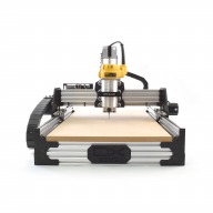
  1. vonsy

    vonsy New
    Builder

    Joined:
    Apr 25, 2016
    Messages:
    7
    Likes Received:
    5
  2. Matt-Sparks

    Builder

    Joined:
    Mar 29, 2017
    Messages:
    10
    Likes Received:
    7
    IMG_2419.PNG IMG_2413.JPG IMG_2392.JPG IMG_2380.JPG IMG_2377.JPG

    I have no experience in making a machine like this so apologies if I have made any mistakes or school boy errors. I just like gadgets and making s#*t and this machine is bloody brilliant I'm well pleased

    1500mm by 1500mm

    Got this package last Friday! I do think who ever packed it has OCD issues even the tape with mm perfect. Two days grafting and I was cutting.

    Packaging 100%
    Instructions 98% only had two small issues mainly due to not reading the instruction. I did find the Y axis motor connection was running in reverse but was simple enough to fix.
    Parts 100% all look and feel quality.
    Build 100% would be easier if the eccentric nuts where at the top but I'm sure there is a reason for them being at the bottom.
    Commissioning info 100% entered all the data on the sheet and over a 900mm test (the length of my steel ruler) it was bang on it really was accurate.

    So far I have cut

    6mm MDF
    12mm MDF
    18mm MDF
    21mm OAK
    40mm OAK (engraved some letters

    I know I'm using the wrong router bits but I'm now skint so will have to wait a few weeks before getting so decent bits. Any recommendations for starter but would be appreciated.

    All the cuts to date are very accurate. 300mm circles are perfect mirror copies every time. You can see some tool makes but I guess this will improve with descent bits. The 21mm oak finish was the best finish and I did set this to 15 passes which was quite slow. Only trouble I do seem to have is the rebates some time filling with saw dust which seems to cause a poor finish on the thicker MDF. I'm hoping up cut but will reduce this.

    I'm not one for kissing *** or writing reviews but respect where respect is due. As Andy from the barley pickers would have said. Proper Job.

    Any chance of some free limit switches for the glowing review? And is it possible to add one of the fancy z axis calibration test link?

    Thanks Ryan and your team.
     
    GrayUK likes this.
  3. Marcus1

    Marcus1 New
    Builder

    Joined:
    Jan 13, 2017
    Messages:
    65
    Likes Received:
    13
    Matt
    Nice Build.

    The Quality of bits will improve side finish (using the correct feed and speed)as long as the correct stratergy is used, But the bottom finish is down to Z being perpendicular to the bed (Tramming).

    I have a trammer for my mill, but cannot use this on the OX as the Z depth is too great. Does anyone know of a trammer that can be used?
    upload_2017-5-4_7-44-18.png
     
  4. srod

    srod New
    Builder

    Joined:
    Mar 11, 2017
    Messages:
    11
    Likes Received:
    0
    Hi Marcus,

    sorry for the late reply, been so busy.

    All is good now after loads of trial and error and messing with feeds and the like.

    I now run with 1/4" cutting diameter up-cut 2 flute spiral bits from routercutter.co.uk and they are fantastic bits. 1200mm/min feed with a cutting depth of no more than 2mm and I ramp into all cuts. Bit stays cool to touch. Only remaining issue I had was the z-axis being dragged down during grooving, but I do have a heavy dust shoe attached to the router and ramping up the power to the z-axis has more or less cured this. A little bit of movement remains, but I will switch the dust shoe for a lighter one when I get around to it and am pretty confident that will sort it out once and for all.

    Thanks.
     
  5. Marcus1

    Marcus1 New
    Builder

    Joined:
    Jan 13, 2017
    Messages:
    65
    Likes Received:
    13
    Vetric Toolpath Strategy

    Gents (and Ladies)

    Does anyone have a good Strategy for milling multiple through cuts in MDF using Vetric.
    I have tried most options but it seems that either edge detail or precision is not brilliant.

    The best I have got so far is....

    3mm Spiral Compression cutter running at 24000rpm and 3600mm/min (Plunge same as it has a spiral ramp)

    upload_2017-5-4_15-53-52.png

    If I add any leads they seem to be added outside the part I want to cut - not inside.
    Also I seem to get a witness as the tool withdraws and I cannot see how to take it off the cut face
    Does anyone have experience???

    Cheers

    Marcus
     
  6. Ryan Lock

    Ryan Lock Veteran
    Builder

    Joined:
    Oct 12, 2014
    Messages:
    530
    Likes Received:
    292
    @Matt-Sparks Thanks for the great write up and pictures, we love seeing them! I think i have given all our packers OCD, they are the ones now moaning at me for not packing things perfectly. An upcut bit should help with this and help bring the Debris to the top. Do you want to PM your order id, and i can sort something out for limit switches. Z axis calibration test link, is what Marcus posted you meant? You probably could make a home made one using a metal bar and two indicators.

    @Marcus1 I would turn off separate last pass, i have found using this can give a poor edge finish as it cuts it full length. I tend to prefer leave an allowance, and take off the final bit using a separate tool path using multiple passes. I am unsure why it is adding ramps to the outside, if you send me the vectric file i can take a look.
     
  7. Marcus1

    Marcus1 New
    Builder

    Joined:
    Jan 13, 2017
    Messages:
    65
    Likes Received:
    13
    Ryan

    Thanks for looking and answering.

    OK - I have followed your advice - First and second Cut Strategy....Merged
    upload_2017-5-5_11-24-42.png upload_2017-5-5_11-26-35.png upload_2017-5-5_11-28-59.png
    Preview.....

    upload_2017-5-5_11-31-27.png

    Gives This G Code

    I will cut and send a photo

    Cheers

    Marcus
     

    Attached Files:

  8. Matt-Sparks

    Builder

    Joined:
    Mar 29, 2017
    Messages:
    10
    Likes Received:
    7
    Thanks Marcus

    The trammer looks a brilliant bit of kit. I will try and make a gadget that fits the ooz
     
  9. Matt-Sparks

    Builder

    Joined:
    Mar 29, 2017
    Messages:
    10
    Likes Received:
    7
    Hi Ryan

    Yes I will confirm parts and order with you shortly. The Z calibrate different to Marcus had subjected although that is a well worth while. It's more Z zeroing using a metal plate and creating a circuit with wire and croc clips. Is this possible with the controller?


    Thanks
     
  10. Marcus1

    Marcus1 New
    Builder

    Joined:
    Jan 13, 2017
    Messages:
    65
    Likes Received:
    13
    Results - Ignore the black dots, this marks where the tool exited
    upload_2017-5-5_12-33-29.png

    Red lines point to overcuts - I presume on the final finish pass as the tool plunges at 45deg ramp

    upload_2017-5-5_12-35-57.png
    As tool retracts after finish - this is left. Presume I need to overcut, but without leads I cannot

    upload_2017-5-5_12-37-47.png

    Issues everywhere!!!!!!

    Any advice? PLEASE :)

    Marcus
     
  11. Marcus1

    Marcus1 New
    Builder

    Joined:
    Jan 13, 2017
    Messages:
    65
    Likes Received:
    13
    I you do make two!!!!

    :) Marcus
     
  12. Ryan Lock

    Ryan Lock Veteran
    Builder

    Joined:
    Oct 12, 2014
    Messages:
    530
    Likes Received:
    292
    Yes it is possible:

    Z-probe on the V2 really isnt too bad - all you need is a conductive plate (of known thickness) and some alligator clips and wiring. As for wiring, they will need to connect the A5 pin to the tool and the plate to ground (or vice versa). Similar to this:

    Move your spindle close to the plate in the X Y plane. then lower your Z until the tool is somewhat close to the plate (this is really just to save you time). Next execute command:

    G38.2 Z-20 F1000

    * Note here the Z-20 is how far to travel before considering the test a "Probe Failure" so you number might need to be more depending on how far away from the plate you are.

    ** A5 pin is located on pin 5 of the IDC expansion header on the board.
     
  13. Ryan Lock

    Ryan Lock Veteran
    Builder

    Joined:
    Oct 12, 2014
    Messages:
    530
    Likes Received:
    292
    Sorry pictures didn't show above i just copied an pasted it. PM your email, and i can send them across.

    @Marcus1 I can't understand why it is doing that, it should ramp within the profile. Could you send me the source Vectric file?

    Ryan
     
  14. Marcus1

    Marcus1 New
    Builder

    Joined:
    Jan 13, 2017
    Messages:
    65
    Likes Received:
    13
    Thanks for looking here is the vetric file

    Whoops - cannot upload that file type.
    Have renamed it dxf - when you get it rename to crv3d and it should be good
    Marcus
     

    Attached Files:

  15. Marcus1

    Marcus1 New
    Builder

    Joined:
    Jan 13, 2017
    Messages:
    65
    Likes Received:
    13
    Matt

    I think this is more a function of the SW you use to interpret the G Code. I am using Mach3 and I do use the Z probing method supplied with the 2010 screen set.

    Marcus
     
  16. Marcus1

    Marcus1 New
    Builder

    Joined:
    Jan 13, 2017
    Messages:
    65
    Likes Received:
    13
    Bingo

    Think I have found the issue.
    Mach 3 will run in Constant velocity or Exact mode (G61- G64 to cancel)
    Switching to exact the cuts are supurb (even though a little slower and jerkyer).
    Apparently CV mode smooths the transitions keeping up the speed of movement

    Hope that helps someone going through the same pain

    Marcus
     
    crispin likes this.
  17. Matt-Sparks

    Builder

    Joined:
    Mar 29, 2017
    Messages:
    10
    Likes Received:
    7
  18. Ryan Lock

    Ryan Lock Veteran
    Builder

    Joined:
    Oct 12, 2014
    Messages:
    530
    Likes Received:
    292
    Great News!! Thanks for posting the solution :)
     
  19. Ryan Turner

    Builder

    Joined:
    Mar 1, 2016
    Messages:
    68
    Likes Received:
    13

    I've got your same setup but with a Dewalt, where did you get your dust boot or did you build it?
     
  20. Matt-Sparks

    Builder

    Joined:
    Mar 29, 2017
    Messages:
    10
    Likes Received:
    7
    Hi,

    I got the dust boot from ooznest. I'm sure I could have made some things cheaper but as the machine is in my office I didn't want dust everywhere. To be honest it's a well made bit of kit. You and see through the top of it and it clips in on magnets so very easy use.

    How's are you getting on with your cnc?
     
  21. Ryan Lock

    Ryan Lock Veteran
    Builder

    Joined:
    Oct 12, 2014
    Messages:
    530
    Likes Received:
    292
  22. andrew openshaw

    Builder

    Joined:
    May 1, 2017
    Messages:
    5
    Likes Received:
    0
    Hi Ryan,

    I must be missing something obvious but i have downloaded and unzipped UGS, but i can not see the universalGcodesender.jar file.
    Can you tell me where it is

    thanks

    Andrew

    upload_2017-5-12_15-41-40.png
     
  23. Matt-Sparks

    Builder

    Joined:
    Mar 29, 2017
    Messages:
    10
    Likes Received:
    7
    IMG_2585.JPG My one looks like this is thats any help.


  24. Marcus1

    Marcus1 New
    Builder

    Joined:
    Jan 13, 2017
    Messages:
    65
    Likes Received:
    13
    Gents/Ladies

    Does anyone have a good handle on how tight the GT3 Belts should be. I have now had a few issues with (as it turns out) loose belt tension.
    Is there a guide on how to set it?

    Cheers

    Marcus
     
  25. Ryan Lock

    Ryan Lock Veteran
    Builder

    Joined:
    Oct 12, 2014
    Messages:
    530
    Likes Received:
    292
    Hi, i think this is because you have download the UGS Platform, there should be a second link which is UGS Classic GUI.

    Its a hard thing to say, but i have the machine screwed down to a table, and pull one end of the belt with pliers using all my weight (Average build). This gets it so it thuds when pinging to where it comes over the track to go to the pulley.

    Ryan
     
    Marcus1 likes this.
  26. Matt-Sparks

    Builder

    Joined:
    Mar 29, 2017
    Messages:
    10
    Likes Received:
    7
    IMG_2587.JPG Hello Marcus,

    I have doubled up the belts and it's working very well. I use a 40mm angle bracket and two 25mm m4 screws nuts and washers. I gave the belts a firm but not to hard tug while the wife nipped up the screw. It's a bit ruff and ready but working great


    QUOTE="Marcus1, post: 53548, member: 64633"]Gents/Ladies

    Does anyone have a good handle on how tight the GT3 Belts should be. I have now had a few issues with (as it turns out) loose belt tension.
    Is there a guide on how to set it?

    Cheers

    Marcus[/QUOTE
     
    Marcus1 likes this.
  27. Marcus1

    Marcus1 New
    Builder

    Joined:
    Jan 13, 2017
    Messages:
    65
    Likes Received:
    13
    Ahhh

    I just tried that and the belt broke where the nip up screw had been:)
    Have ordered some more belt that I was going to double up - will have to order 2 more Metres

    Thanks to all
     
  28. Marcus1

    Marcus1 New
    Builder

    Joined:
    Jan 13, 2017
    Messages:
    65
    Likes Received:
    13
    Matt - I am intending to double belt - what advantages have you seen?

    Marcus
     
  29. Matt-Sparks

    Builder

    Joined:
    Mar 29, 2017
    Messages:
    10
    Likes Received:
    7
    Morning Marcus

    I fitted double belts from the start so have no experience without the. I read some thread and watched some YouTube clips and it just sounded a good plan. I have the 1500mm by 1500mm and that seemed a long belt to me. Because both belt teeth sit nicely together the forces are transferred down both belts which reduces the stretch. It's only relying on the single belt as it comes up from the v wheels over the gear and back to the v wheel. All I can do is that my machine has been bang on from day 1. I had my first belt jump yesterday but the was due to a g code error the and router trying to push 8mm in one pass. A nicer clamping method would be to order some of the v channel blanking plates you would need 12 of them but it would look a lot nicer than my Heath Robinson job and the angle brackets.

    Hope this helps.

    Matt
     
    Marcus1 likes this.
  30. kaffemannen

    Builder

    Joined:
    Feb 14, 2017
    Messages:
    7
    Likes Received:
    0
    Has anyone outfitted the ooznest OX with printer head? Would love to see a part list for that!
     

Share This Page

  1. This site uses cookies to help personalise content, tailor your experience and to keep you logged in if you register.
    By continuing to use this site, you are consenting to our use of cookies.
    Dismiss Notice