Welcome to Our Community

Some features disabled for guests. Register Today.

My CNC Router Built Around The New C-Beam Rail

Discussion in 'CNC Mills/Routers' started by Robert Bailey, May 30, 2015.
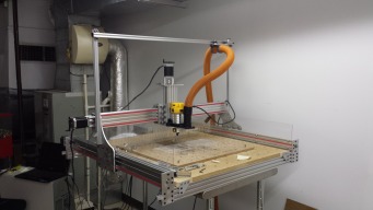
  1. superelvis

    Builder

    Joined:
    Sep 21, 2015
    Messages:
    22
    Likes Received:
    1
    hello robert,

    I am new to the router scene... I wanna buy a kit over v-slot europe... I see there are two controllerboards avaliable (Arduino-GShield and TinyG)

    Is there a big difference or limitations between this two boards....(software and speed??)
     
  2. Steven Bloom

    Steven Bloom Journeyman
    Builder

    Joined:
    Dec 18, 2014
    Messages:
    194
    Likes Received:
    104
    That looks cool with the inside and outside wheels. you could even do double wheels on the outside with another plate on the other side to lock it in. Could you imagine 24 wheels all together. It would never move the wrong way.
     
    silopolis likes this.
  3. Robert Bailey

    Robert Bailey Well-Known
    Builder

    Joined:
    Mar 23, 2015
    Messages:
    117
    Likes Received:
    71

    I don't have the grbl shield, have the tinyg. the tinyg allowed me to have dual steppers on the Y axis, one on each side. you do have a limit of a little over 2 amps per driver, but haven't ran into issues. I
    have my limit pots turn up to about 2/3rds running a 10 amp 24volt supply. the grbl only supports 3 steppers if I recall. the only limit I ran into was the a max velocity over 3000mm per min caused it
    to skip and twist the gantry, I have it set to 2000 to be safe and works fine. for software the grbl has panel, tinyg has pepper(online only), there are a few gcode senders that work as well, but no linuxcnc or mach
    integration that I have seen.
     
  4. Robert Bailey

    Robert Bailey Well-Known
    Builder

    Joined:
    Mar 23, 2015
    Messages:
    117
    Likes Received:
    71
    $$ by the time you add 24 wheels you could redesign for a rail system. we did think about using the small truck that came with my first combo to see if it would make a difference on the x. I don't have any
    extra c-beam to try on the Z, we are still hoping to figure it out, just haven't had tome to tweak it, I have it here at work so we have to wait till after 5 to play with it.
     
    Steven Bloom likes this.
  5. superelvis

    Builder

    Joined:
    Sep 21, 2015
    Messages:
    22
    Likes Received:
    1
    Hallo Robert,

    Thanks for you reply!
    Do you think its possible to mill objects like this with the OpenBuils OX (gshield/arduiono)?


    [​IMG]
    [​IMG]
     
  6. Mark Carew

    Mark Carew OpenBuilds Team
    Staff Member Moderator Builder Resident Builder

    Joined:
    Jun 28, 2013
    Messages:
    2,745
    Likes Received:
    2,410
    Hi @superelvis I will jump in here if I may,
    Yes you can mill 3D patterns like this using the right tool pathing cam software. ArtCAM for instance
    In fact I find its easier to cave then it is ti cut all the way though materiel.
    You would use step down cuts removing a little material on each depth cut.
    Check out this forum post
    http://www.camheads.org/showthread.php?t=3401
    Also have a look at this Standing Wave Generator Resource
    http://www.openbuilds.com/resources/standingwave-generator.84/
    Hope this helps
     
    silopolis and superelvis like this.
  7. Robert Bailey

    Robert Bailey Well-Known
    Builder

    Joined:
    Mar 23, 2015
    Messages:
    117
    Likes Received:
    71
    Don't see why it wouldn't, I am trying 6061-t6 aluminum which is some hard stuff, the softer materials so far are a breeze. I cut almost 200 holes in the work surface into mdf and didn't even break a sweat.

    look at the area-51 build and videos he is doing signs in wood and throwing wood chips everywhere.
     
  8. Mark Carew

    Mark Carew OpenBuilds Team
    Staff Member Moderator Builder Resident Builder

    Joined:
    Jun 28, 2013
    Messages:
    2,745
    Likes Received:
    2,410
    Also be sure to check out some of the Showcase carvings done on the OX
    [​IMG]
     
    superelvis likes this.
  9. leversole

    leversole New
    Builder

    Joined:
    Nov 1, 2015
    Messages:
    77
    Likes Received:
    14
    Any progress on this? I am thinking of build my Ox with all C-Beam...I assume the nut block is attached with the two screws thru the top? Do you have this idea in a sketchup file? You can post or email me if you like...

    PS...I really appreciate all that you have done in/for Openbuilds...I am am going to end up with a machine I could onely have dreamed of before!

    PSS...I went back and looked again, would this be a good design for the Z axis?
     
  10. Robert Bailey

    Robert Bailey Well-Known
    Builder

    Joined:
    Mar 23, 2015
    Messages:
    117
    Likes Received:
    71
    Well it has been a while since I updated anything, been real busy. Finally figured out the aluminum. got some single flute mills off ebay for
    about a $1.50 each they sell them as .125 but measure as .115, runs through the 6061 as well as the $32 bit. Also added air to blow the chips out.
    just got some alumatap cutting oil and it helps too. My coworker who is helping me, his daughter named the machine frank, after Frankenstein. we
    have been calling it Frankinator since it is going to build itself like the terminators. We are in the process of drawing up new plates to handle the bigger bearings I found, also found a better 8mm shaft clamp. the bearings came off ebay and the clamps were ordered from global industrial. The controller will be in the pelican case, got it free from work. we think we fixed most of the flex in the Z-axis by adding wheels on the backside of the X gantry. didn't cost much since the 40mm was already mounted and spaced correctly. our next Y plates will flip the C-Beam so the screw will be on the backside, gets a lot of crap slung up into it when milling.
     

    Attached Files:

    Mark Carew likes this.
  11. Mark Carew

    Mark Carew OpenBuilds Team
    Staff Member Moderator Builder Resident Builder

    Joined:
    Jun 28, 2013
    Messages:
    2,745
    Likes Received:
    2,410
    Well done @Robert Bailey great looking projects! Thanks for sharing :thumbsup:
     
  12. SteveB05

    SteveB05 New
    Builder

    Joined:
    Nov 24, 2015
    Messages:
    5
    Likes Received:
    0
    Great project @Robert Bailey. I'm just getting my design worked out and I would very much like to get the PDF of your side plates. I'd even throw some beer money your way via PayPal :)
     
  13. Robert Bailey

    Robert Bailey Well-Known
    Builder

    Joined:
    Mar 23, 2015
    Messages:
    117
    Likes Received:
    71
    here they are, this is our current design, I have a coworker draw these up in solid works. me and another coworker are in the process of a redesign to incorporate our rear wheel add-on as seen in the previous pictures
    I have uploaded. our new design for the gantry will set the spindle back a couple inches, I have several plates that are 14"Hx10W so I am making it fit that dimension. the new design will also is also using a
    22mm bearing that has a lip to hold in in instead of having a pocket. as it sits now we are able to cut wood, aluminum and plastic. more updates to follow in the next week or 2.
     

    Attached Files:

    silopolis likes this.
  14. SteveB05

    SteveB05 New
    Builder

    Joined:
    Nov 24, 2015
    Messages:
    5
    Likes Received:
    0
    Perfect!! Thank you.
     
  15. Robert Bailey

    Robert Bailey Well-Known
    Builder

    Joined:
    Mar 23, 2015
    Messages:
    117
    Likes Received:
    71
    Found an error in the X plates is is .9 mm off on the wheel spacing , based on the universal plates. might be why I was having problems setting up the wheels
     
  16. SteveB05

    SteveB05 New
    Builder

    Joined:
    Nov 24, 2015
    Messages:
    5
    Likes Received:
    0
    Ok. I'll make that adjustment and verify against the plates that come with the kit when it gets here. What I was thinking is running the X axis C-Beams with the screws to the outside (like yours) with the x-plates on the outside and have the risers on the inside. That should reduce the deflection in the C-Beam without adding drag by putting more of the moment of the force on the solid side of the C-Beam. Also want to do that on the Y axis beam (screw to the back). I think this will give the best rigidity available this side of a fully supported rod setup while keeping the screws as clean as possible. Thoughts? This is my first build of a device like this and I'm not an engineer. I don't see anyone else doing that so I might not be thinking about something.
     
  17. Giarc

    Giarc OpenBuilds Team
    Staff Member Moderator Builder Resident Builder

    Joined:
    Jan 24, 2015
    Messages:
    2,916
    Likes Received:
    1,619
    I saw this and was going to ask why there was a difference. I have designed my plates using the 99.7 mm between the top and bottom wheels because that was the spacing on the various plates in the parts store. Then I noticed 100.6 mm in some builds and I was going to ask someone before I start drilling. This was a timely topic. Is the 99.7 correct? Thanks.
     
  18. Robert Bailey

    Robert Bailey Well-Known
    Builder

    Joined:
    Mar 23, 2015
    Messages:
    117
    Likes Received:
    71
    my coworker works in solid works 8 hours a day, so we downloaded the library from the resources, so it might not be correct. we tried to cut aluminum this sat. but the new version of sketchucam does outside climb milling CCW and we broke the bit, here are ne new designs, not finished, we are going to flip the X beam so the screw is to the rear. There may be errors in the design so no promises.
     

    Attached Files:

    silopolis likes this.
  19. Giarc

    Giarc OpenBuilds Team
    Staff Member Moderator Builder Resident Builder

    Joined:
    Jan 24, 2015
    Messages:
    2,916
    Likes Received:
    1,619
    Those are nice plates. I plan to see if I can do everything using my existing tools and no CNC, so my shapes are pretty much limited to the "square-ish" profile. ;) I could probably find someone that could cut them for me, but I just gotta try without first. Thanks for answering. I will stick with the 99.7.
     
  20. Robert Bailey

    Robert Bailey Well-Known
    Builder

    Joined:
    Mar 23, 2015
    Messages:
    117
    Likes Received:
    71
    our first plates were hand drilled and we cut them on a chop saw with an aluminum blade we picked up at home depot.
     
  21. David the swarfer

    David the swarfer OpenBuilds Team
    Staff Member Moderator Builder Resident Builder

    Joined:
    Aug 6, 2013
    Messages:
    3,278
    Likes Received:
    1,835
    eh? you can cut either direction on outside cuts, just tick or untick the 'overhead gantry' checkbox.
    to quote the help:
    Code:
    2) "Overhead Gantry". The original 2 Phlatprinters cut from the bottom with a reversed Y axis. Use this option if you have a Phlatprinter3 or your cnc machine has an overhead gantry. This will reverse the direction of the Inside and Outside cuts.
    See the Options Menu help for setting this as a default 
     
  22. Robert Bailey

    Robert Bailey Well-Known
    Builder

    Joined:
    Mar 23, 2015
    Messages:
    117
    Likes Received:
    71
    thanks, I never had any other cnc, just jumped in head first. that fixed the outside cuts but all my inside cuts are now CCW, Thoughts?
     
  23. David the swarfer

    David the swarfer OpenBuilds Team
    Staff Member Moderator Builder Resident Builder

    Joined:
    Aug 6, 2013
    Messages:
    3,278
    Likes Received:
    1,835
    an outside cut cuts around the thing you want to keep. you want the best finish on the edge of the part you keep, right?
    some machines give a better finish with a climb cut, and others with a convensional cut.

    the same goes for inside cuts, it is cutting out a piece that you will discard, so the good finish should be left on the part that is left behind, therefore it cuts in the other direction.

    your problem is more likely not the direction of the cuts, but rather your speeds and feeds, and probably cut depth and maybe you did not use ramping.
    not all bits are made for plunging down into the work, which is why you can set a separate plunge feed in the parameters, this is normally set slower than the normal feed speed to give a bit tie to clear the chips when plunging.

    another solution is to use the ramping option (I actually use this for everything now). This will feed the tool in at an angle, trying quite hard to never plunge directly down into the work. watch out for plunge holes though, if they are 'bit size' they will plunge in anyway. do read the help about this feature, it explains a lot that you need to know.

    even on the small Cbeam machine (ie relatively stiff) you can expect cut depth to be 0.5mm per pass in aluminum. stepover % should not be more than 30% in aluminum, and for slot cutting you really need to get the speeds and feeds right since the stepover is then 100%.

    feeds and speeds are not something you guess at, they can and should be calculated, at least as a starting point!
    not that feeding too slowly is just as bad as too fast, go shallow rather than slow.

    Depending on the specific aluminum alloy you are cutting you will have more or less stickyness, where the aluminum sticks to the edge of the cutting tool. This is very bad. There are various very good cutting fluids that prevent this, like Aluma-cut, or you can use kerosene or even beeswax. NOT WD40 - it does work but it is actually a water displacer, not a lubricant.

    Feeds and speeds calculator - an online resource | OpenBuilds
    Speeds and feeds for wood and plastics | OpenBuilds
     
    silopolis and Mark Carew like this.
  24. Robert Bailey

    Robert Bailey Well-Known
    Builder

    Joined:
    Mar 23, 2015
    Messages:
    117
    Likes Received:
    71
    yep I have a bottle of alumi cut, been using it. I am working on 6061-t6 with a .115 single spiral flute carbide bit, doc=.0156(1/64) router set to lowest rpm (15,800), .5 inch plunge rate and one time the speeds and feeds calculator had me at 24 inch per now it is saying 7.66, think that tool goes bonkers
     
  25. David the swarfer

    David the swarfer OpenBuilds Team
    Staff Member Moderator Builder Resident Builder

    Joined:
    Aug 6, 2013
    Messages:
    3,278
    Likes Received:
    1,835
    according to my (simple) speed calculator you should be running that bit above 34000 rpm at 69 to 139 IPM for a ~2 thou per rev chipload. halve the ipm for 1 thou per tooth chip.

    rather look at the manufacturers spec sheet for the bit, .5inch plunge seems way too slow to me, it will rub most of the time, then dig in (and break!), it needs to be constantly cutting and clearing the chips, if the chips are too big (feedrate too high) they get stuck, if too small, they clog, or it rubs then digs in which makes the chip much bigger than desired.

    Please watch my videos on Youtube on doing multi cut drawings with SketchUcam. Using this technique you can cut anything in any order or direction you like.

     
  26. Robert Bailey

    Robert Bailey Well-Known
    Builder

    Joined:
    Mar 23, 2015
    Messages:
    117
    Likes Received:
    71
  27. Robert Bailey

    Robert Bailey Well-Known
    Builder

    Joined:
    Mar 23, 2015
    Messages:
    117
    Likes Received:
    71
    Here is another set of bits I have 3.175 mm 17mm CEL 1 Flute Carbide End Mills Router Bit we did a cut last night and it went well, but I was running 7.66 ipm .0156 doc at 15,800 rpm, this evening we will try what the formula calls for from amana bits 600fpm (50") 18,336 rpm and .002-.004 fpt my only issue is the DOC it says 1xD which would be .115 seems a little deep, but breaking a 2 dollar bet is better than a $30 one.
     
  28. Robert Bailey

    Robert Bailey Well-Known
    Builder

    Joined:
    Mar 23, 2015
    Messages:
    117
    Likes Received:
    71
    well we ran some cuts last night, 50 IPM 18,500 RPM with a DOC of .004 then .0156 , holy crap it was slinging aluminum the parts got just a little warmer than room temp but we were cutting a small part, I created a 1/8inch spacer to go behind the screw block. here is a pic of the result after a scotch brite wheel taken to it to take off the sharp edges.
     

    Attached Files:

  29. David the swarfer

    David the swarfer OpenBuilds Team
    Staff Member Moderator Builder Resident Builder

    Joined:
    Aug 6, 2013
    Messages:
    3,278
    Likes Received:
    1,835
    nice! science works, it seems (-:
     
  30. Robert Bailey

    Robert Bailey Well-Known
    Builder

    Joined:
    Mar 23, 2015
    Messages:
    117
    Likes Received:
    71
    Had a productive Saturday, got the Y end plates cud and tried my first crack and engraving acrylic, its a surprise for my nephews wedding.
     

    Attached Files:

    Giarc likes this.

Share This Page

  1. This site uses cookies to help personalise content, tailor your experience and to keep you logged in if you register.
    By continuing to use this site, you are consenting to our use of cookies.
    Dismiss Notice