Welcome to Our Community

Some features disabled for guests. Register Today.

M4: 1510SS Heavy Mk.I

Discussion in 'CNC Mills/Routers' started by Rob Taylor, Aug 22, 2020.
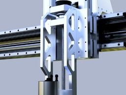
  1. Rob Taylor

    Rob Taylor Master
    Builder

    Joined:
    Dec 15, 2013
    Messages:
    1,470
    Likes Received:
    746
    While I'm thinking about it, a few pictures of where everything is currently at after fixing the column plates (which I still want to paint white, but it's probably not practical).

    Templating out the drill holes to connect the steel tubes to the C-Beam. I think throwing ~100 M5 screws at each side will do the trick. Hopefully won't significantly degrade the tube with those holes in it vs the simulation, we'll see.

    Photo Feb 25, 16 37 43.jpg

    Just dismantled the end plate drill jig and set the shoulder to be half the difference in width between the 3" tube and the C-Beam (about 1.8mm):

    Photo Feb 25, 15 47 49.jpg

    The gantry is put together, the NEMA 24 (60mm) motor fits very nicely inside the 60mm gap with minimal persuasion, which is great. I'd wondered if it would refuse to fit. Hadn't even thought about end caps for the gantry, which is weird. I'll have to come up with something, definitely not as beefy as the steel Y axis plates though.

    Photo Feb 25, 17 19 37.jpg

    Haven't yet trammed these rails, I'll need to do that before I screw the steel tubes on I guess. I might not though, I might just wait and use the V-Slot as a straightedge to tram to once it's in place and all the deflection it's gonna do is locked in. Still haven't decided how I'm gonna attach the C-Beam columns to the uprights yet. I'll probably have to address that next.

    Photo Feb 25, 17 11 53.jpg

    Anyway. It's big. I'm a fan! I didn't even have to cut the gantry extrusions. They're stock 1500mm(!), with 1200mm rails on there. Hopefully this thing doesn't knock me out while I'm standing to the side of it. Building the planned enclosure could be a little tricky now.
     
    Mark Carew likes this.
  2. JustinTime

    JustinTime Veteran
    Builder

    Joined:
    Dec 18, 2013
    Messages:
    759
    Likes Received:
    253
    Holly guacamole, Rob. Looking at theses pictures the first thought that came to my mind was 'he must have $10,000 just in screws in this project'! :D

    I'm exaggerating of course to make a point.
     
    Giarc and Peter Van Der Walt like this.
  3. Rob Taylor

    Rob Taylor Master
    Builder

    Joined:
    Dec 15, 2013
    Messages:
    1,470
    Likes Received:
    746
    No kidding! Even buying them inexpensively from Amazon it adds up, but averaging forces over a lot of fasteners is a time-honoured technique. Individual M5s and tapped aluminum may not be very strong, but on the aggregate I'm sure they can take pretty substantial forces.

    Photo Feb 28, 07 05 42.jpg

    (There's actually more in there now than when this picture was taken, too)

    So I spent the last week basically drilling and sanding steel, and that's about it.

    Photo Feb 28, 06 53 56.jpg

    Predrilled all the 5mm holes on the spotted contact (non-welded) side with an 1/8" bit, then enlarged them to 5.5mm. Then used those as guides to drill 5mm holes on the non-contact side. Then enlarged all of those to 10mm to take the M5 cap heads. 216 holes, four times. Took a while!

    Photo Mar 04, 14 51 56.jpg

    Polished out the three non-contact sides- slack belt of the finger sander on the corners, random orbital on the faces. Only took 60 grit to get to a finish that actually reflected objects (though not a mirror finish, obviously). It's a beautiful finish, actually, contrasting with the holes. I'd have it as a decor aesthetic. :D

    Then I hit the contact sides as little as possible. The longer beam was pretty much dead straight already.

    Photo Mar 07, 12 12 27.jpg

    The shorter beam I had to take out a bit of a hump in the middle, using a mix of both sanders.

    Photo Mar 07, 12 12 11.jpg

    They didn't need to be perfectly flat across the whole face, or parallel to any other faces, just needed to be able to lay flat on the C-Beam without being distorted enough to warp it. Crown wouldn't transfer over, and small amounts of bow would come out simply by tramming the linear rails to the table, but any twist would inevitably transfer to the rails and move the spindle in Y during an X move. No good. I'd originally anticipated the possibility of being forced to buy some 0% VOC laminating epoxy and level it that way but, being hot-rolled, the tubing was in pretty good shape, and a couple of mild tweaks got it good enough for my liking. Less than 0.3mm across the entire length of the short one and zero in the long one, and no discernable twist on either.

    Next I need to figure out if I'm gonna weld on any gussets or brackets before I paint them. Seems like a good idea, but it might be more work than I feel like adding to the project right now. Maybe I won't even paint them yet, maybe I'll try them out in the fit-up first with a partial screw load. A finish this smooth won't rust too easily any time soon, especially if I give it a good degrease and wipe down with some oil. Easy to tack weld to as I go if I need to, and then remove, degrease again and paint. We'll see. I really need to work on the columns and figure out how they're gonna work. It should come together pretty quickly after that, just the Z-axis plates to work on.
     
    Giarc likes this.
  4. Rob Taylor

    Rob Taylor Master
    Builder

    Joined:
    Dec 15, 2013
    Messages:
    1,470
    Likes Received:
    746
    The beams look great in place! They're each held in by 8 screws for now while I figure out what I'm doing. Pulled the 6" relay rack post out to see, it's a 45U/84" post- pre-drilled 3/16" C-channel, basically- so it'll have to be cut to length and drilled for the back of the gantry. It'll be nice having all of those tapped holes in place to attach things to:

    Photo Mar 11, 17 35 38.jpg

    The two 480mmm C-Beams go on the outsides of the aluminum columns. I'm considering just strapping the gantry to the columns through the fixture holes for now and starting on the Z axis so I actually know where it needs to go based on where the spindle ends up. I don't want to end up with unusable space at the front, but I also don't need it so far forward that it can hit the Harmonic Drive. I think there's about 40mm of adjustment room on top of those columns, so it's not a huge deal, but big enough that it could potentially be significant down the road.

    The breaker box was supposed to be a "chip backstop" while I was drilling but it didn't work that well and ended up falling over from the vibrations- if you were wondering about the one hole that didn't get drilled, a piece of drill bit was snapped off inside there when the box fell and shocked the frame, and after killing two more bits trying to open it up, I decided it wasn't really that important anyway. :oops: It's gonna have the Mean Well RSP-1000-48 power supply and the five stepper drivers in it once I get that far.
     
    Mark Carew likes this.
  5. JustinTime

    JustinTime Veteran
    Builder

    Joined:
    Dec 18, 2013
    Messages:
    759
    Likes Received:
    253
    OK, Rob, now I know for sure that you have stocks in the screw factory. :)

    I wonder why you decided to put the two steel beams that way. I would have thought that having one mounted at the back of the main beam would be more conducive to more rigidity.
     
  6. Rob Taylor

    Rob Taylor Master
    Builder

    Joined:
    Dec 15, 2013
    Messages:
    1,470
    Likes Received:
    746
    Hmm, maybe I didn't explain all of my thinking in the simulation posts earlier. I partially addressed it in another thread here:

    So twist, due to the leverage of the long Z-axis, is the weakest deflection mode of the gantry- the extrusions tied together by a wide plate is gonna take care of vertical bow, and horizontal bow in Y isn't really gonna be a thing at that distance. Anything at the back is going to twist across its weakest section- think twisting the middle of a plastic ruler that's clamped at the ends- now do it with a pair of pliers and see how much worse it is. I'm now using 3/16" C-channel instead of 1/4" plate so it should be significantly stronger, but I'm not really relying on the back plate to do anything beyond just holding the three V-Slot extrusions together and prevent sag.

    The two steel tubes, for the gantry to twist, due to their separation and flat orientation, have to actually bend in their strongest direction (the same reason the C-Beams are laying flat) in order to twist the gantry about its center axis. If you grab the imaginary spindle at the end of its 14" arms and push and pull it to twist the gantry, you're effectively trying to bow the steel tubes across their long axis- crowning them, in carpentry terms. That's a lot harder to do than it would be to push in the middle of their flats and bend them across the one-inch dimension, right?

    Hopefully that made sense, especially with the simulation images. Might be easier with a cross-section diagram.
     
  7. JustinTime

    JustinTime Veteran
    Builder

    Joined:
    Dec 18, 2013
    Messages:
    759
    Likes Received:
    253
    Yeah, I didn't think of the twist. I was thinking of the bending/sagging of the beam. Now it make sense.
     
    Rob Taylor likes this.
  8. Mark Carew

    Mark Carew OpenBuilds Team
    Staff Member Moderator Builder Resident Builder

    Joined:
    Jun 28, 2013
    Messages:
    2,745
    Likes Received:
    2,410
    Incredible workmanship on this one Rob! Enjoying following along.
     
    Rob Taylor likes this.
  9. ljvb

    ljvb Well-Known
    Builder

    Joined:
    Feb 14, 2019
    Messages:
    276
    Likes Received:
    87
    Where do you buy your metal supplies?
     
  10. Rob Taylor

    Rob Taylor Master
    Builder

    Joined:
    Dec 15, 2013
    Messages:
    1,470
    Likes Received:
    746
    Currently slow progress- waiting on pulleys from China that I knew I should have ordered in January so I could start the ball nut spindles but didn't because I thought I should calculate belt lengths first, and realized I was wasting a ton of time over $2 in shipping charges- plus belts are way easier to find domestically in decent variations than pulleys. Also waiting on some 4x24x5/8" MIC-6 plates for the z-axis. Decided I couldn't find a way to use V-Slot that I liked, and I really couldn't be bothered a) attempting to straighten 3/4" 6061 plate in the press that still has casting stresses in it, b) it's too long for my mill, and the only other option is to c) manually grind/lap it into flatness (a bit like the steel beams, but a lot more work) with the surface plate and some prussian blue. $60 seemed like a reasonable consequence to "none of the above", so now I'm back to waiting.

    Because the X and Y axes are technically kinda done, I may start on some wiring harnesses/cooling loops, getting some electronics in enclosures, motor mounts, etc. Stuff that's pretty easy to do without needing other parts done first. Should start looking into drag chains and stuff as well, I think. Glad I discovered openable chain in the meantime, feeding wires through closed chain on the laser was pretty miserable (and didn't really help the anti-tangle aspect of things).

    Meanwhile, here's how things look at the minute. Got the (2.2kW, water-cooled, for those just joining) spindle out to do some measurements for the Z axis (seems like the arms may be a fair bit shorter than I'd anticipated for the spindle mount on the moving bearings, which is great), which is dwarfed by the machine itself:

    Photo Mar 24, 15 59 11.jpg

    The gantry attachment plates are just 1/4". They lock up the gantry surprisingly well, but I need to add something on the back to add more rigidity in addition to the rear plate (which is also on there now, at least partially, I'll have to get more pics at some point).

    Planning on possibly zipping this all up with one of the thinner 3M VHB tapes in final assembly for absolute maximum rigidity and to rely a little less on screws- might even be able to save some weight that way.

    Thanks man! Long way from single-axis camera sliders, eh!? Hopefully should come together within the next month or so.

    Honestly, just eBay. The usual suspects, MetalOnline, 6061dude, all those people. Takes some shopping around to optimize for shipping, but the prices are never too bad. So far less than $200 of aluminum into this machine, pretty sure, and I bought like $320 worth or something? Nice to have materials in-stock though. The 1x3x1/8x60" tubes were high shipping of course, but I also got them on a Seller Offer because I put them on a watch list, I think it was about $70 shipped for both. With patience and a little experience, you can get pretty good prices on materials online.
     
  11. ljvb

    ljvb Well-Known
    Builder

    Joined:
    Feb 14, 2019
    Messages:
    276
    Likes Received:
    87
    Yeah, I have been looking around. Someone pointed me to https://www.howardprecision.com/random-rack/ (their off cuts and drops I guess). I got a quote for 1/4 13" * 36" Mic6 plate and (2) 1/4 12 x 22" 6061 for around $80 shipped. I'm debating on going up to 1/2 maybe. I'm following the Piranha build here.. which was close to what I was designing, but since they already finished it, why do extra work myself. Their plates are based on 6mm (but getting 6mm was pricey for some reason, 1/4 which is a hair thicker was much cheaper)

    I have not ordered anything yet.
     
    #41 ljvb, Mar 24, 2021
    Last edited by a moderator: Apr 1, 2021
  12. Paul Amelang

    Builder

    Joined:
    Nov 28, 2020
    Messages:
    9
    Likes Received:
    3
    Rob, this looks amazing. Thanks for documenting your build so well. Would you be generous enough to post the Fusion 360 files so that I could poke around your design and try to learn a thing or two? I'm especially interested in examining how you mount your ball screws and nut.

    I'd like to build a heavy duty router with a 4'x2' work area and I'm trying to decide which design to go with. It looks like a handful of people here have upgraded their machines to ball screws with good effect but their maximum feed rate may be limited by screw whip. I'm very inexperienced, but it seems like high feed rates would be necessary to be able to cut metal efficiently with a high speed spindle.
     
  13. Rob Taylor

    Rob Taylor Master
    Builder

    Joined:
    Dec 15, 2013
    Messages:
    1,470
    Likes Received:
    746
    I have no current intention of releasing the files- in general, I have a blanket "no files" policy, including 3D print files, etc. It's also not very helpful for this particular project anyway, because I keep changing things as I go depending on what's practical to build or if I've come up with a better solution in the meantime. So these files aren't enormously useful to anyone except myself as a general build guideline.

    I do intend on producing some general dimensional drawings as I get closer to a finished solution, however- which should be sufficient for reproduction by anyone with the capacity to replicate the build. Though in the meantime, I've documented so much that a careful reader could probably actually replicate the whole thing from scratch without any plans, which is always my intent- I'm not a fan of sparsely-documented builds; the point here is to demonstrate existing solutions to be built upon.

    The issue with high feed rates with a high speed spindle is material removal rate, which directly correlates to spindle power. The type of cutting in non-ferrous metals that these spindles can do in woods and plastics would probably require at least a 10HP spindle, potentially up to 20 or 30HP, in order to get the required high-end torque which drops off pretty severely. And a significantly different frame design; likely welded and epoxied.

    Screw whip is a real concern, which is why I'm using fixed screws. I haven't actually tacked the rotating ball nut assemblies yet, which is why you don't see much of them in here yet. It could be overkill vs a good tensioned-screw setup with high-pitch ball screws, but it allows for future upgrades to servos at up to 6x the operational speeds (~15,000mm/min rapids), and is entirely scaleable to 8, 10, 12, 20ft machines (though at 20ft the modularity of rack and pinion would probably take far more precedence). Tensioned 16mm ball screws are always going to be limited at 1500mm to around 1200rpm, which isn't too much of a safety factor above potential high speed closed-loop stepper rates at appropriate voltages.

    Ball screw mounts are addressed pretty thoroughly in this post (in addition to the original CAD views): M4: 1510SS Heavy Mk.I

    Ball nut assemblies, as I say, haven't been tackled yet but there's a pretty good section view on the main build page that shows how they should end up working. I only recently received the timing pulleys so that I could start looking at that stuff, and haven't yet had a chance.

    Currently working on the X screw assembly, which is just a basic screw setup- 1200mm is theoretically much better for whip. This is the combination motor/screw bearing mount so far:

    Photo Apr 09, 14 21 32.jpg

    Photo Apr 09, 15 16 19.jpg

    Just gotta drill the four end holes to actually mount the parts, and then decide whether I think it's gonna need another block to connect the other four screw holes. I suspect the answer is no, given how tight everything is inside the 60mm C-Beam space.
     
  14. Rob Taylor

    Rob Taylor Master
    Builder

    Joined:
    Dec 15, 2013
    Messages:
    1,470
    Likes Received:
    746
    Some progress on the Z axis this week. I've had other projects in the shop, so it's been a little bit slow lately.

    Photo Apr 23, 11 56 33.jpg

    Gotta figure out where I'm gonna set up the carriage/arms at. I want the spindle to be able to get a tiny little 1/16x1/8" or whatever end mill down to the horizontal center plane of the rotary, so where it is now on those 1-2-3 blocks might still be a little high. I also want at least four inches between carriages on the Z, so we'll see where it all ends up.

    Photo Apr 23, 11 56 57.jpg

    Pulling the film off the MIC-6 is the best. Glad I opted for this option, those things are dead flat- no daylight underneath on the surface plate. Hopefully 5/8" is enough thickness- that was the only thickness available in the size and quantity I wanted- but there are gonna be gussets on there so it should be fine.

    The 3-jaw chuck is seized on my lathe- not sure if rust or stray chip- and I've been trying to get it off for a couple weeks with copious quantities of penetrants and increasingly aggressive techniques, to no avail, so it's getting to the point where either a) I figure out a one-shot method of turning the ball nut spindles (pretty doable, most of the features are on one side), or b) farm out the work to one of these online job shops like Xometry or whatever. Since re-turning if the nuts don't fit is not very doable at that point, I'm inclined to just continue in the 3-jaw with the 12L14 bar stock that I have and see where I get. I don't think I've killed the bearings, they feel and sound fine, so pulling the spindle to say, ice/torch the chuck off) can wait for later.
     
  15. HuguesP

    HuguesP Well-Known
    Builder

    Joined:
    Jan 14, 2018
    Messages:
    30
    Likes Received:
    43
    Very different from the usual work, looking foward for this diy rotating ballnut setup. You should really clamp your ballscrews end so they don't rotate

    keep going!
     
    #45 HuguesP, May 5, 2021
    Last edited: May 7, 2021
    Rob Taylor likes this.
  16. Rob Taylor

    Rob Taylor Master
    Builder

    Joined:
    Dec 15, 2013
    Messages:
    1,470
    Likes Received:
    746
    There are optional set screws in the steel plates- I don't remember if I actually drilled and tapped them, but I made space for them in the CAD model, and certainly intend to make sure they're there before final installation of the plates. First I have to figure out the Y axis ballnut assemblies before I care about any of that though.

    Meanwhile, I think I've cracked the code on the Z axis. This has been giving me grief for quite a while, but after being away from the project for a month or so with periodic trips down into the shop to stare at it and hold parts together, I got the distance to come up with a solution. Fingers crossed it works, we'll see how it goes once I start machining the plates.

    So I have the Z rails on (temporarily, just like pretty much the entire machine still at this point) and I made the Z axis carriage plates:

    Photo Jul 04, 04 48 24.jpg

    Still aiming at around 300mm of Z (obviously deflection will be higher at the top, but I don't anticipate cutting anything that thick that isn't soft woods, plastics and probably mainly foams):

    Photo Jul 04, 04 49 48.jpg

    X-axis motor and ball screw are effectively fully installed at this point- I ground parallel flats into the screw itself so I could wrench on the bearing lock nut. I'll have to take the floating end bearing off to install the ball nut mount, I didn't get one of the split ones, but that's not a problem.

    Nabbed an 80mm spindle mount for only $15, apparently they all come pretty rough-cast? Anyway, I turned down the faces and bored it out, very slightly oversize but within the clamping range of the screws. It wasn't very round to begin with so I just had to make an executive decision when to stop cutting. Clamping pressure should be fine.

    Photo Jun 02, 17 20 58.jpg

    And then machined the back and sides, using the spindle itself as the parallel, and swept in tilt in X to a couple thou. Once cut it was flat enough to hold in the vise to do the rest of it. Obviously that means when it's unclamped it'll bow, but that's not much of an issue, it should be fairly repeatable. Spindle holding doesn't really need to be too incredibly precise, as long as it can move in a couple of degrees of freedom to tram in.

    Photo Jun 24, 08 12 33.jpg

    Spent a few weeks pretty much staring at this view, trying to build the axis in my head:

    Photo Jul 04, 04 48 59.jpg

    Those upright plates will probably be the last thing I cut though, since I need to size them to keep the spindle from hitting the rotating nut housing. Which I just spent the last few days finalizing, I think I'll start cutting plates here in the next day or two. This is a render from when I was nearly finished:

    ZAxisPlates_2021-Jul-03_10-21-26PM-000_CustomizedView11399159982.jpg

    Gonna go with an aluminum nut spindle for now- I actually don't think the forces on it are such that I see any significant advantages from going with steel, but I have the material if I do need to. Precisely turning aluminum is obviously much faster and easier to do so I should get a result sooner. I almost considered resin printing the spindles in something like Siraya Blu, but I figured it'd be better to stick with metal for now.

    So things are moving again, now that some stuff- both shop work and life- is now out of the way. Yay!
     
    Alex Chambers likes this.
  17. Rob Taylor

    Rob Taylor Master
    Builder

    Joined:
    Dec 15, 2013
    Messages:
    1,470
    Likes Received:
    746
    Quick update, things are still progressing on the X/Z axis!

    X nut block installed, fits very nicely in the 60mm gap with a little bit of wiggle room. X main plate installed, and Z motor plate cut and ready to screw on. Just gotta do the bearing flange backplate that connects them together and then we're fully into the Z axis side of it. I'll probably make the X axis standoff block when I do the Z motor standoffs. They'll just be drilled and tapped 3/4" round bar, exactly like the mill conversion Z axis standoffs.

    Photo Aug 04, 06 25 40.jpg

    If it feels like it's going slowly, it's because it is! I still have other things going on. But I want this machine finished!

    Photo Aug 04, 06 29 03.jpg

    It's not gonna be too much longer until the Z axis seems to suddenly pop together fully-formed. Then it's just a case of getting the Y screws done and motor mounts made, and the whole thing should be ready to start getting into motion. Wiring will be some work, but it shouldn't be a problem, I already have the drag chains. There'll be a lot of tramming and screw calibration after that though!
     
    Mark Carew likes this.
  18. David the swarfer

    David the swarfer OpenBuilds Team
    Staff Member Moderator Builder Resident Builder

    Joined:
    Aug 6, 2013
    Messages:
    3,275
    Likes Received:
    1,833
    do you watch Peter Stanton? he has a video showing how his big Mazak mill/turn swaps between lathe and C axis mode. The lathe motor is belted to the spindle (free running), but the milling motor is a servo->worm drive to the spindle which can be taken into and out of engagement by the hydraulics which act on an M code.

    So, the answer is 2 motors , 1 for lathe, 1 for milling.
     
    Rob Taylor likes this.
  19. Rob Taylor

    Rob Taylor Master
    Builder

    Joined:
    Dec 15, 2013
    Messages:
    1,470
    Likes Received:
    746
    I have watched one or two of his videos, he's really good, though I haven't seen that mechanism. That's an interesting idea though, and would probably be fairly easy to achieve with an optical encoder for proper positioning during changeover. I have a bunch of 120V motors and a couple of three-phase motors laying around, so I definitely have options there. Easier to drive a worm drive back and forth, I'd have to come up with a good clutch mechanism and add a lot more framing to the front end, but definitely something to keep in mind. Would be hugely powerful with some swiss-style block tooling on the Z axis.

    M4 is currently in pieces because we just moved a couple of months ago, but the mill will be up and running soon and then it'll be back to business!
     
  20. David the swarfer

    David the swarfer OpenBuilds Team
    Staff Member Moderator Builder Resident Builder

    Joined:
    Aug 6, 2013
    Messages:
    3,275
    Likes Received:
    1,833
    this video shows the drawings though I recall a video showing the mechanism but cannot find it
     
    Mark Carew likes this.

Share This Page

  1. This site uses cookies to help personalise content, tailor your experience and to keep you logged in if you register.
    By continuing to use this site, you are consenting to our use of cookies.
    Dismiss Notice