Welcome to Our Community

Some features disabled for guests. Register Today.

Linear Rail OX

Discussion in 'CNC Mills/Routers' started by sgspenceley, Feb 13, 2015.
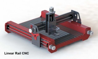
  1. sgspenceley

    sgspenceley Veteran
    Builder

    Joined:
    May 27, 2014
    Messages:
    249
    Likes Received:
    291
  2. Hytech2k

    Hytech2k Veteran
    Builder

    Joined:
    May 6, 2014
    Messages:
    429
    Likes Received:
    331
    Very Nice !!
     
  3. sgspenceley

    sgspenceley Veteran
    Builder

    Joined:
    May 27, 2014
    Messages:
    249
    Likes Received:
    291
    Thank you this was a lot of 3D modeling, but mathematically accurate and fully parametric so when parts arrive from China I can check the dimensions and the model will update and adjust automatically!
    Now I'm working on the rack and pinion version, which I'm going to nick name the "Extra Strong OX" using the same extrusion as your Strong OX..
     
    #3 sgspenceley, Feb 13, 2015
    Last edited: Feb 16, 2015
  4. Florian Bauereisen

    Florian Bauereisen Well-Known
    Builder

    Joined:
    Feb 24, 2014
    Messages:
    188
    Likes Received:
    60
    Hi there,
    nice cad work i must say.
    If i was you i would not waste my money on these round linear rails, especially as you mentioned your intrest in milling
    aluminum acurately...
    Use the square type and buy pre-loadet ( V1 or V2 ) type "cars" for it.
    sice 20 mm rails should be enough for cutting aluminum.
    Not too much more expensive but definetly worth the money.

    think along this line:
    "if your are going anyway you might go the whole way".

    greets from munich

    flo
     
  5. Hytech2k

    Hytech2k Veteran
    Builder

    Joined:
    May 6, 2014
    Messages:
    429
    Likes Received:
    331
    Extra Strong Ox or "ESO", I like it !! You'll have to design some pretty thick spacers to get the rack close enough to the motor. :)
     
  6. Hytech2k

    Hytech2k Veteran
    Builder

    Joined:
    May 6, 2014
    Messages:
    429
    Likes Received:
    331
    What is the distance between the outside of the Y rail and the inside of the Y axis plate? If it's close to 1/2-3/4" a 20 degree pressure 20 pitch rack would fit in the nicely since its 1/2 x 1/2 or 1/2 x 3/4 depending on the supplier.
     
  7. sgspenceley

    sgspenceley Veteran
    Builder

    Joined:
    May 27, 2014
    Messages:
    249
    Likes Received:
    291
    Thank you flo. Greeting to Munich, I have spent many fun trips here, working with BMW.
    Can you send me a link for the square bar you are suggesting?
    Funny I just finished a regular OX, and decided to upgrade to this design thinking it was a lot better!

    Gerald I was thinking about using some solid bar to provide the require spacer.
     
    #7 sgspenceley, Feb 13, 2015
    Last edited: Feb 13, 2015
  8. Hytech2k

    Hytech2k Veteran
    Builder

    Joined:
    May 6, 2014
    Messages:
    429
    Likes Received:
    331
    I think Flo is talking about the NSK or HiWin type of linear rails. They have the square rails with pre-loaded cars.

    If the space is no more then 3/4" I would just use the 20 pitch rack, there would be no need for spacers, check out the rack here pre-mounted on a backer plate.
    http://www.cncrouterparts.com/pro-gear-rack-39-1-meter-p-263.html

    But here's the thing really, the Openbuilds extrusions are only available up to 1500mm anyway, so really unless your going with different extrusions with longer lengths I think the design you have is spot on, ballscrews/leadscrews are great for smaller applications like this. The only real advantage for gear rack and pinion is for building a long or very wide machines where leadscrews would be prone to whip...


    Gerald
     
  9. Florian Bauereisen

    Florian Bauereisen Well-Known
    Builder

    Joined:
    Feb 24, 2014
    Messages:
    188
    Likes Received:
    60
    Hi,
    Gerald is right, just search for Hiwin, THK, NSK or Star Germany.... Linear rails and you will find them.
    Flea-Bay if you want to buy used...

    greets

    flo
     
  10. Florian Bauereisen

    Florian Bauereisen Well-Known
    Builder

    Joined:
    Feb 24, 2014
    Messages:
    188
    Likes Received:
    60
    Hi,
    my english beeing not good enough to explain fully but i get you a quick sumary (taken from a reading of a well known/reptated german manufacturer):
    It is mainly due the spread of the loads along the diameter of the setup. The round rails itself works as long as you only load it from top to bottom like a rail( offers max distance of material to take force). maximum loads sideways (side mounted for ex) will be taken only on the biggest diameter wich is a very small portion of the rail ( a dot to be precise). a square rail will take a lot more either direction as there is simply more material spaced maximum appart. ( think I-beam). Same reason as modern planes use square beam for wing joiners.
    The car itself is sorta more complex but generally it is considered that the round ones compare more to a tube cut open and the forces are spread along a surface that is sorta slipping away ( beeing round) from the balls (ballrace) while the square rail offers a channel for each ball to ride along..
    Aditionally you can access data for each square car telling you all the forces (momentum) each direction the car can take... try even find that for the round ones.
    Last but not least, always use what the industry uses... they would use the cheap round rails if these were to offer the same performance as the square ones.
    Will we need that? I don`t know you will have to decide, but looking at my surface on milled aluminium i think it is worth the extra..
    Not too expensive in smaller setups anyway.
    A lot cheaper than upgrading in case you are not satisfied. ( my buddy knows a story or two about exactly that .... lot of money thrown away).

    Hope that explains it a little.
    greets

    flo
     
    JustinTime likes this.
  11. sgspenceley

    sgspenceley Veteran
    Builder

    Joined:
    May 27, 2014
    Messages:
    249
    Likes Received:
    291
    Thank you for the bearing information. I'm not sure if this idea goes beyond my budget. Quick research shows $300 VS $140. But you are 100% correct $140 is more expensive if does not work. So I'm going to try the Y axis first.

    Gerald I tried putting the rack in between the rails and could not find a solution I was happy with. So played with the idea of bolting a rail to the top to strengthen the Y by creating an additional beam.

    Plus is also helps keep dust & chips from failing on the linear bearings.
    LinearOx7.JPG LinearOx5.JPG LinearOx6.JPG
     
    #11 sgspenceley, Feb 14, 2015
    Last edited: Feb 14, 2015
    GrayUK and Hytech2k like this.
  12. Hytech2k

    Hytech2k Veteran
    Builder

    Joined:
    May 6, 2014
    Messages:
    429
    Likes Received:
    331
    That's spot on Steve. I would definitely use the 1/2 x 1/2 20 pitch 20 pressure rack in that situation, just drill and tap the rack every 6-8 inches and attach to that top plate. I have 6 ft of 20/20 rack here, only reason I didn't use it is because I didn't want to have to make spacers to move the plates out far enough to clear the rack, 1/4 x 1/4 works better in my build... You might want to check out Ricks build on belt reduction drives, i'm working on a set now to use with a R&P setup, would double the resolution and torque of those motors along with offering a stronger shaft and bearings for the pinion gear.

    Gerald
     
  13. Florian Bauereisen

    Florian Bauereisen Well-Known
    Builder

    Joined:
    Feb 24, 2014
    Messages:
    188
    Likes Received:
    60
    Hi,
    i must have missed that one, and search did not turn up anything.
    Which build is that? i would be quite intrested.
    Thanks

    flo
     
  14. Nick W

    Nick W Well-Known
    Builder

    Joined:
    Oct 22, 2014
    Messages:
    99
    Likes Received:
    61
  15. sgspenceley

    sgspenceley Veteran
    Builder

    Joined:
    May 27, 2014
    Messages:
    249
    Likes Received:
    291
    #15 sgspenceley, Feb 15, 2015
    Last edited: Feb 17, 2015
    mybuild14, GrayUK and Hytech2k like this.
  16. sgspenceley

    sgspenceley Veteran
    Builder

    Joined:
    May 27, 2014
    Messages:
    249
    Likes Received:
    291
    Next I worked on the main beam design again. I thought if I take the two original 20 * 60 X axis beams and then add two new 20 * 80 extrusions, I could create a very strong box section.

    Basically I have two 20*80 extrusions horizontally, two 20 * 60 extrusion vertically, in addition to the plate than supports the linear bearings.

    My CNCRouterParts nuts arrived Saturday, so I'm going to try this approach first, before going to the expense of ball screws on the X & Y!
    Today produced an accurate 3D CAD model of the anti-backlash nut, so I could work out the correct positions of the X axis & Y brackets.

    Z-Axis-BallScrew8.JPG

    Z-Axis-BallScrew6.JPG Z-Axis-BallScrew7.JPG Z-Axis-BallScrew4.JPG
     
    #16 sgspenceley, Feb 15, 2015
    Last edited: Feb 15, 2015
    Colin Russon, GrayUK and Hytech2k like this.
  17. sgspenceley

    sgspenceley Veteran
    Builder

    Joined:
    May 27, 2014
    Messages:
    249
    Likes Received:
    291
    My first set of X axis linear bearings arrived from China, quality is very good.
    Now they are in "hand" SBR16 are a good size for the X, Y, & Z axis. Bearings are very nicely made with go good dust shields. Amazing quality for $86 for two rails and 4 bearings...
    I would not go down to the SBR12 because the circulating ball bearings will be too small for my taste... If I was building a machine with a long Y axis I would consider SBR20's on a production quality machine.

    Shafts are both very straight, one of the mounting blocks has a "slight" twist along its length, but this will be removed when bolted down.

    With all four bearing surfaces on the two rails I think these will produce a very smooth and strong X axis.

    I purchased from solarjean, packaged arrived very fast from China via DHL about 14 days, free shipping, expertly packaged with great care!
    http://stores.ebay.ca/enjoylife?_trksid=p2047675.l2563
    LinearBearings.jpg LinearBearings2.jpg
     
    #17 sgspenceley, Feb 20, 2015
    Last edited: Feb 20, 2015
  18. shali85

    shali85 New
    Builder

    Joined:
    Feb 20, 2015
    Messages:
    3
    Likes Received:
    0
    Very Nice Build
    Following you.
     
  19. sgspenceley

    sgspenceley Veteran
    Builder

    Joined:
    May 27, 2014
    Messages:
    249
    Likes Received:
    291
    Thank you shali85, when this build is all complete and tested we will be offering custom plates on Geralds new area51 web site... http://area51cncparts.com/
     
    #19 sgspenceley, Feb 20, 2015
    Last edited: Feb 20, 2015
  20. GrayUK

    GrayUK Openbuilds Team Elder
    Staff Member Moderator Builder

    Joined:
    May 5, 2014
    Messages:
    1,668
    Likes Received:
    627
    Hi Steve.
    Can you give me a ball park figure on the cost of the shafts, bearings, and mounting blocks etc?
    Cheers
    Gray
     
  21. sgspenceley

    sgspenceley Veteran
    Builder

    Joined:
    May 27, 2014
    Messages:
    249
    Likes Received:
    291
    Hi Gray
    Two 600mm, case hardened round shafts, 16mm diameter, two 600mm mounting shafts and four bearings was $86 US, free shipping.
    Here in Canada I was charged $20 CDN tax... No getting around that if the parcel is flagged by customs!

    I'm going to mount these on a 1/4" or 3/8" aluminum plate and then mount that to the beam.

    I will now order the linear bearings for the Y & Z axis...
     
  22. GrayUK

    GrayUK Openbuilds Team Elder
    Staff Member Moderator Builder

    Joined:
    May 5, 2014
    Messages:
    1,668
    Likes Received:
    627
    That's a really good price. I'm always so dubious when buying from China.
    It's the "no comeback" if it's wrong that worries me!
     
  23. sgspenceley

    sgspenceley Veteran
    Builder

    Joined:
    May 27, 2014
    Messages:
    249
    Likes Received:
    291
    I agree Gray this is why I only ordered one set!
    I looked locally and they wanted $760 for what looks like the same product SBR16's. So I thought I would try the gamble!
    This seller really packaged well and no issues with quality...
     
  24. GrayUK

    GrayUK Openbuilds Team Elder
    Staff Member Moderator Builder

    Joined:
    May 5, 2014
    Messages:
    1,668
    Likes Received:
    627
    I'll make a note of them!
     
  25. sgspenceley

    sgspenceley Veteran
    Builder

    Joined:
    May 27, 2014
    Messages:
    249
    Likes Received:
    291
    Thank you JustinTime. I agree items that go through the post office if it's below $300 I typically don't get charged HST, with the Free shipping from China I cannot really complain about the surcharge. The only annoying part is the HST was $6 and the processing fee from DHL was $16... A deliver time of around 2 weeks from China was really great.
     
  26. Neil Rosenberg

    Neil Rosenberg Journeyman
    Builder

    Joined:
    Dec 29, 2013
    Messages:
    179
    Likes Received:
    177
    Hi Steve, about time I checked into YOUR build! I love your approach, makes me want to do a very similar machine. As far as I can tell you've covered the bases really well -- stiffness, accuracy, economy, build-ability. Wish I'd seen this before I made the Frog.

    I also see that you've switched to multi-start leadscrew on all axes. Having used that very thing for a month or so now, I totally concur, for this size machine it's great.

    I'm trying to figure out the configuration of the gantry beam. Looks like a sort of "T" configuration. What led you to that particular layout?

    I'm curious, what CAD product do you use, and will you be publishing your models?

    An alternate question --

    Your design is the best that I've seen yet on this board, better in fact than ANY of the commercial high-end-hobby machines out there. Have you considered commercializing this?

    Big pats on the back!
    Neil
     
  27. sgspenceley

    sgspenceley Veteran
    Builder

    Joined:
    May 27, 2014
    Messages:
    249
    Likes Received:
    291
    Thank you Neil for your kind words.
    Your build & Geralds inspired this version along with looking at a friend's big production machine. It became obvious that little mods would never give me the machine I really need for my custom sim racing projects.

    When you consider I need to re-engineer the OX Y axis gantry plates, I need a longer Y extrusion, new end plates it's basically a brand new build.

    So I have decided to go all out and sell my original Aluminium OX which is all complete and running with belts and ideal for hobby work. I have no regrets building the original it was fun & great learning experience. I originally wanted a machine to cut carbon fiber sheet and my plan was to continue using a 3rd party to cut aluminum. But have decided it would be better to cut both parts in-house.

    From a X axis, design perspective. I needed a tall vertical surface to mount the linear bearings on, so a 80*20 was logical, knowing this would flex I thought adding three 60*20 horizontal would be enough, then I decided to make a box section. Two vertical 80*20's & three 60*20's all bolted together. I'm also investigating a large single extrusion from a small CNC company in Pittsburgh.

    I use SolidWorks & Photoworks for designing, it's a really excellent solution but expensive. For most of my career I worked for a company called Alias Research developing 3D surface modeling for the automotive (Autostudio) & entertainment industry (Maya). It was lots of fun in the 90's and early 2000's until Autodesk purchased the company.

    I must admit I'm considering commercializing the design once it's proven itself. Gerald will be cutting the first prototype plates for me once all the additional parts arrive.

    Thank you Neil...
     
    #27 sgspenceley, Feb 23, 2015
    Last edited: Feb 23, 2015
  28. Neil Rosenberg

    Neil Rosenberg Journeyman
    Builder

    Joined:
    Dec 29, 2013
    Messages:
    179
    Likes Received:
    177
  29. sgspenceley

    sgspenceley Veteran
    Builder

    Joined:
    May 27, 2014
    Messages:
    249
    Likes Received:
    291
    Thank you for the links, I would consider the 3" x 6" nothing smaller in width. Ideally I would like 4" * 6" extrusion.

    I use SolidWorks 2014 premium.

    Agree the urge to build again is really strong, because it lots of fun designing and engineering. I have been having loads of fun & spending far too many hours in SolidWorks playing with design concepts...

    The original Ox is a wonderful tastier CNC project targeted at a specific group of people. Of that group a small number will want a much stronger & more precise version. You and Gerald both proved you can mod the design to go to the next level. I'm hoping to go one step beyond that and I don't mind learning from but ignoring the original design constraints. Such as wheels that run in a V-slot.

    I have a friend how purchased CNCRouterParts Pro series machine with steel wheels, who recently switched his machine to linear bearings in the hope to make the machine more robust... I'm now so pleased I did not buy this machine!

    The Ox route has been far more fun!
     
  30. Neil Rosenberg

    Neil Rosenberg Journeyman
    Builder

    Joined:
    Dec 29, 2013
    Messages:
    179
    Likes Received:
    177
    I looked at the CNCRouterParts Pro, if only as a reference point. Honestly it doesn't look much if any beefier than what I have now, and I've sort of had it with rollers/wheels. Give me a real linear bearing, preloaded and precision, riding on a well supported ground shaft. Incredibly, as you've already found, it's just not that much more money.

    Perhaps some day OpenBuilds will start a "Pro Line" of parts, but probably not. If they do however, they may be surprised at the reaction.

    If you go up on Ebay or even Amazon, there are dozens of similar crappy CNC routers, you know, the ones that use ground steel rods as the entire strength of the carriage, and even though some of these have a beam nearby, none of them actually touch except at the ends. They look impressive but ... yuk! Here's a for-example (priced at $1700):

    [​IMG]

    I even saw one that was just 2 bars, no other horizontals at all, and it was 4 feet across! About as stiff as spaghetti, I'm sure.

    I think you and I are of a breed -- reminds me of an old quote of Doc McCoy (Star Trek): "I know engineers, they LOVE to change things".

    Can't really justify building another machine, but darned if I don't want to!

    P.S. I use Solidworks 2010. I can give you files but not the inverse except if it's STL or some-such that can't be edited. Darn!
     

Share This Page

  1. This site uses cookies to help personalise content, tailor your experience and to keep you logged in if you register.
    By continuing to use this site, you are consenting to our use of cookies.
    Dismiss Notice